How to Program a PIC Microcontroller & Read an Encoder
by CarsonMiller in Circuits > Microcontrollers
46824 Views, 38 Favorites, 0 Comments
How to Program a PIC Microcontroller & Read an Encoder
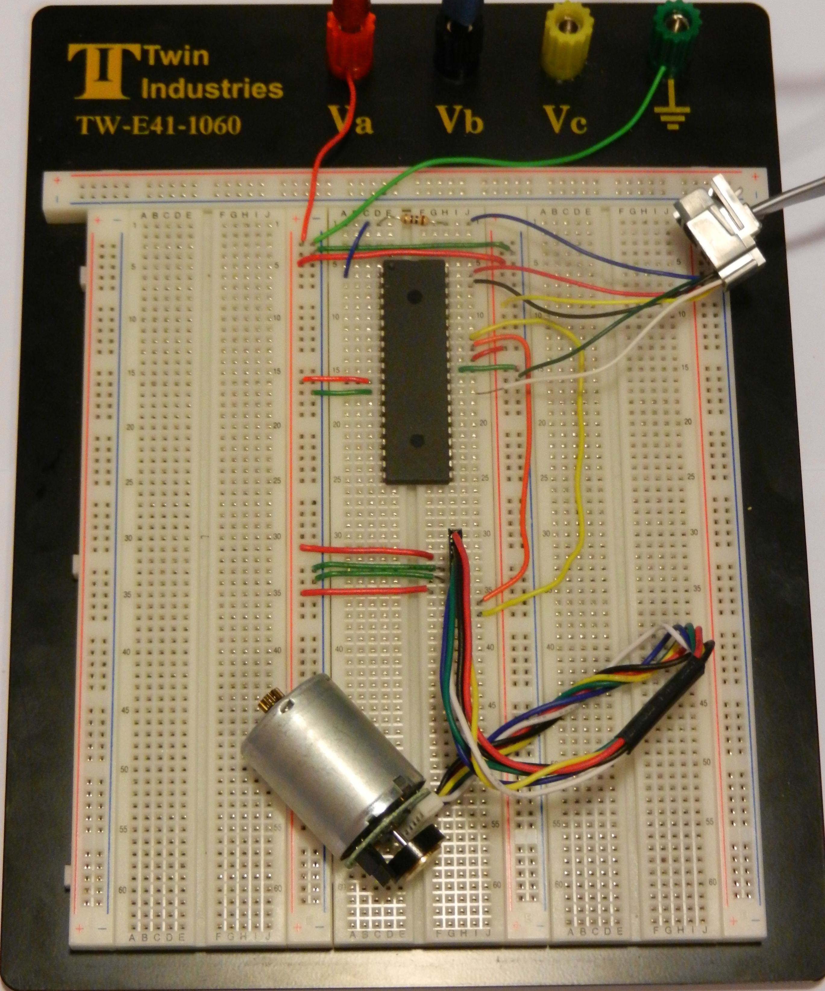
What to know: Before we get started though, there's some prior knowledge that will not be covered in this guide. If you'd like to brush up your knowledge on any of those topics (listed below), feel free to check out the links.
Voltage: https://learn.sparkfun.com/tutorials/voltage-curre...
Voltage Measurement: https://learn.sparkfun.com/tutorials/how-to-use-a-...
Breadboarding: https://learn.sparkfun.com/tutorials/how-to-use-a-...
Oscilloscope Use: http://eeshop.unl.edu/pdf/OscilloscopeTutorial--Be...
Materials

Software:
MPLAB X IDE (Free from: http://www.microchip.com/pagehandler/en-us/family...
MPLAB XC8 (Free from: http://www.microchip.com/pagehandler/en_us/devtoo...
Hardware:
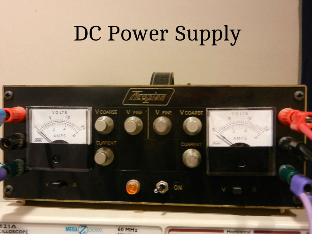
DC Power Supply
Banana Cables
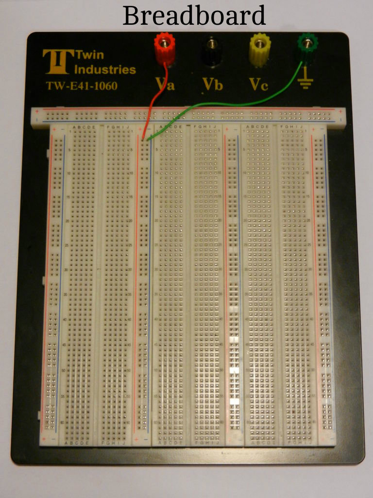
Breadboard
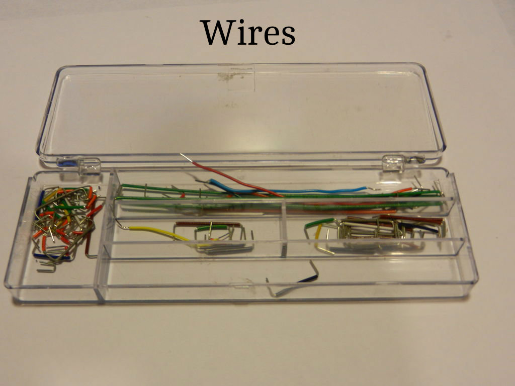
Wires
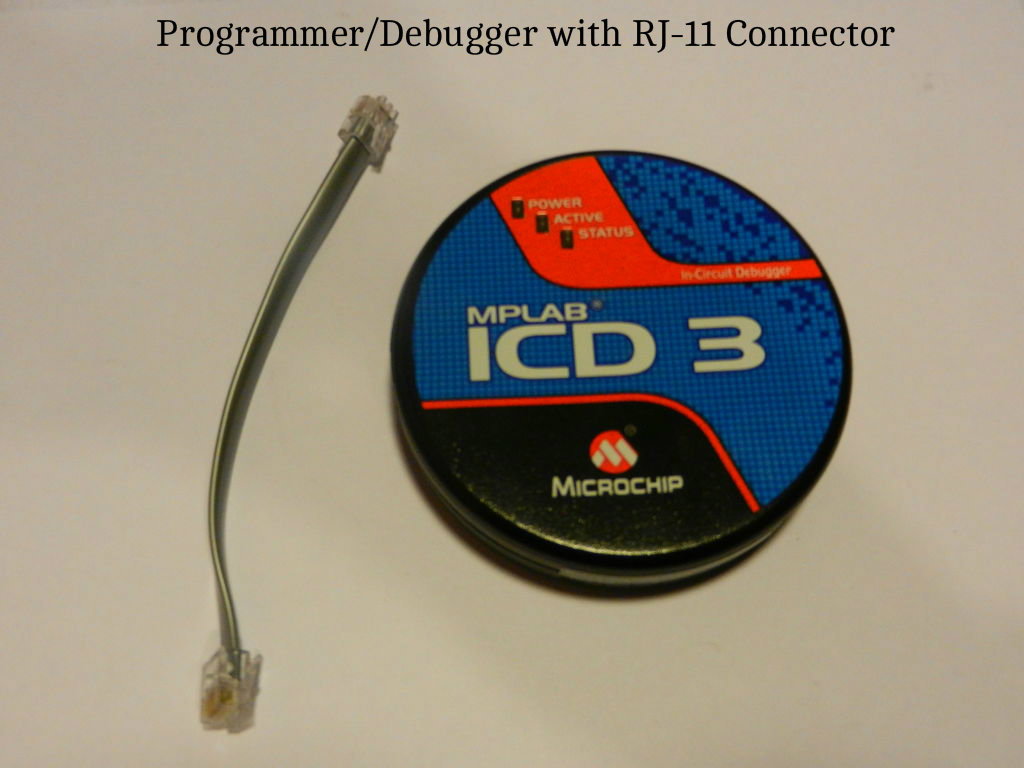
PIC Programmer/Debugger* (MPLAB ICD 3)
RJ11 Connector [Included with MPLAB ICD 3]
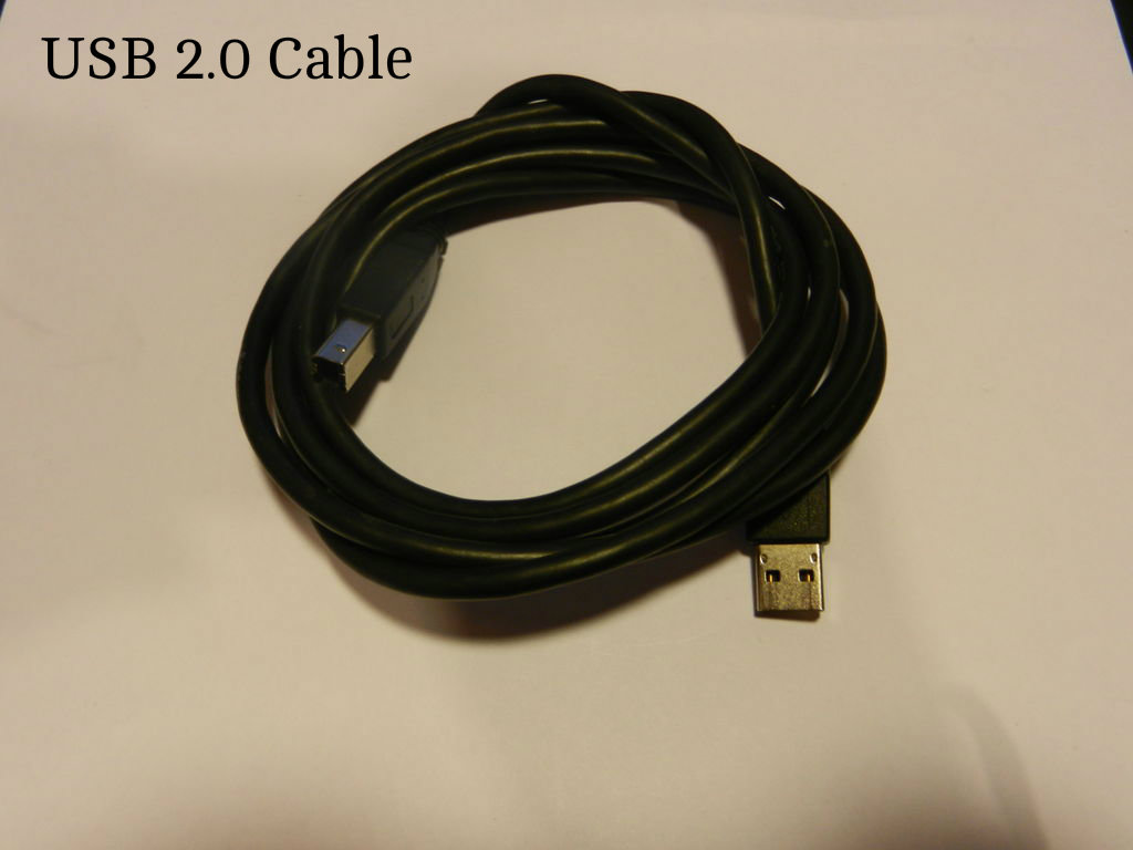
USB 2.0 Cable [Included with MPLAB ICD 3]
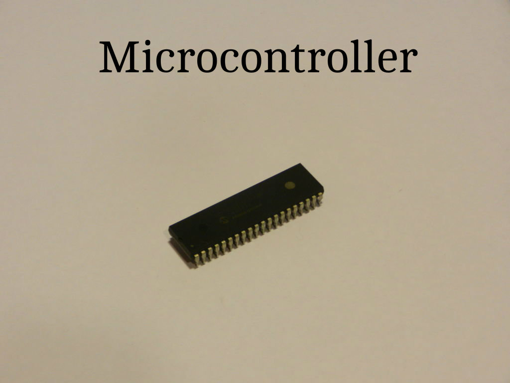
PIC Microcontroller* (PIC18F4520) - Be sure to use a DIP microcontroller so that it can be put into a breadboard.
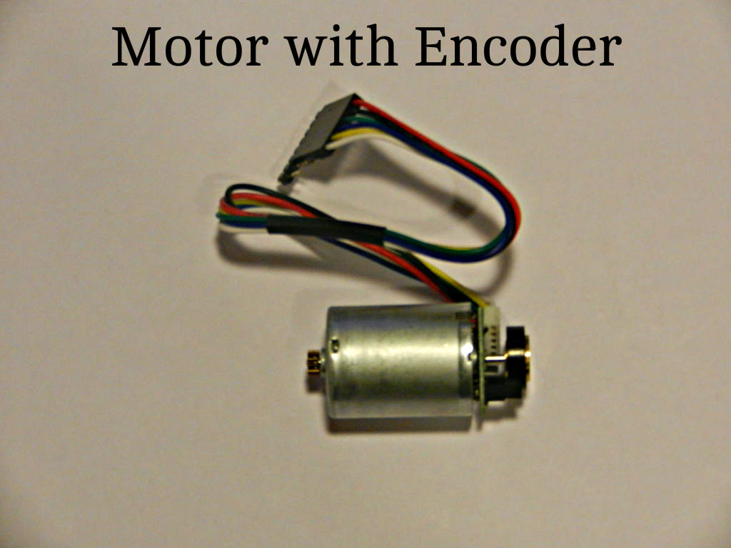
Device with a rotary encoder* (Pololu Item # 2269)
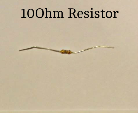
10Ohm Resistor
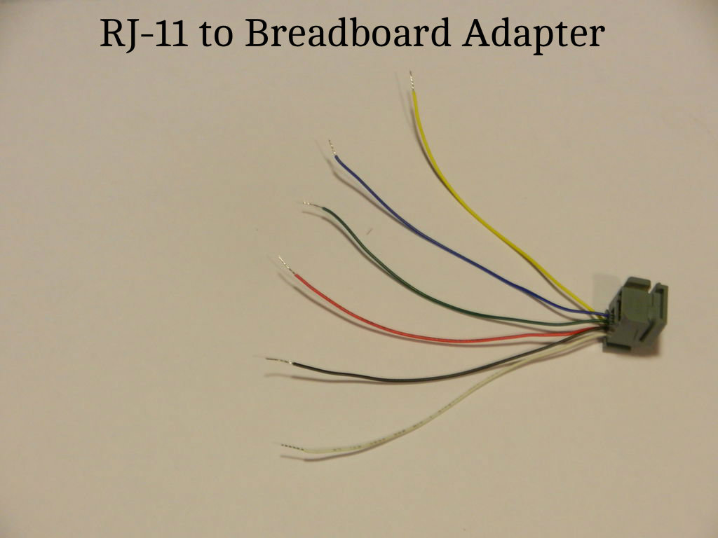
RJ-11 to Breadboard Adapter (DigiKey # H11394-ND)
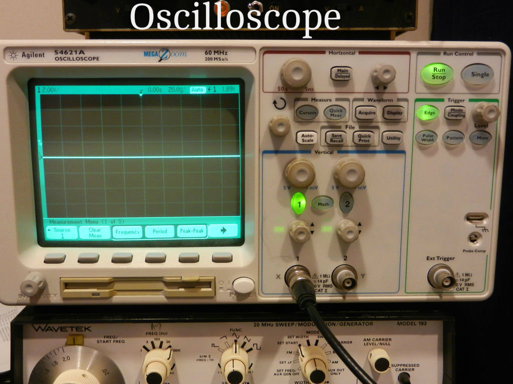
Oscilloscope (Optional) - Allows you to see encoder signals
Oscilloscope Probes x 2 (Optional)
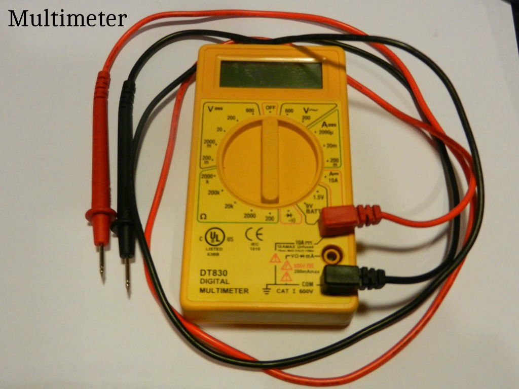
Multimeter (Optional) - Helpful for debugging issues
Power Supply Setup
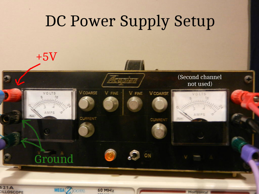
Power Supply: As you'll see in the picture of the Acopian DC power supply pictured in this step, each power supply channel has three colored connectors to which banana cables can be connected. For the purposes of this tutorial, we'll need +5V and +0V (ground) from the power supply. In order to supply +5V and +0V, connect the negative terminal and grounded terminal of the power supply together (the green and black terminals in the picture provided). Then attach a banana cable to both the positive (red) terminal and the grounded (green) terminal that will be connected to the breadboard. These terminals, found on the breadboard, are shown with connected banana cables in step 3.
Breadboard Setup
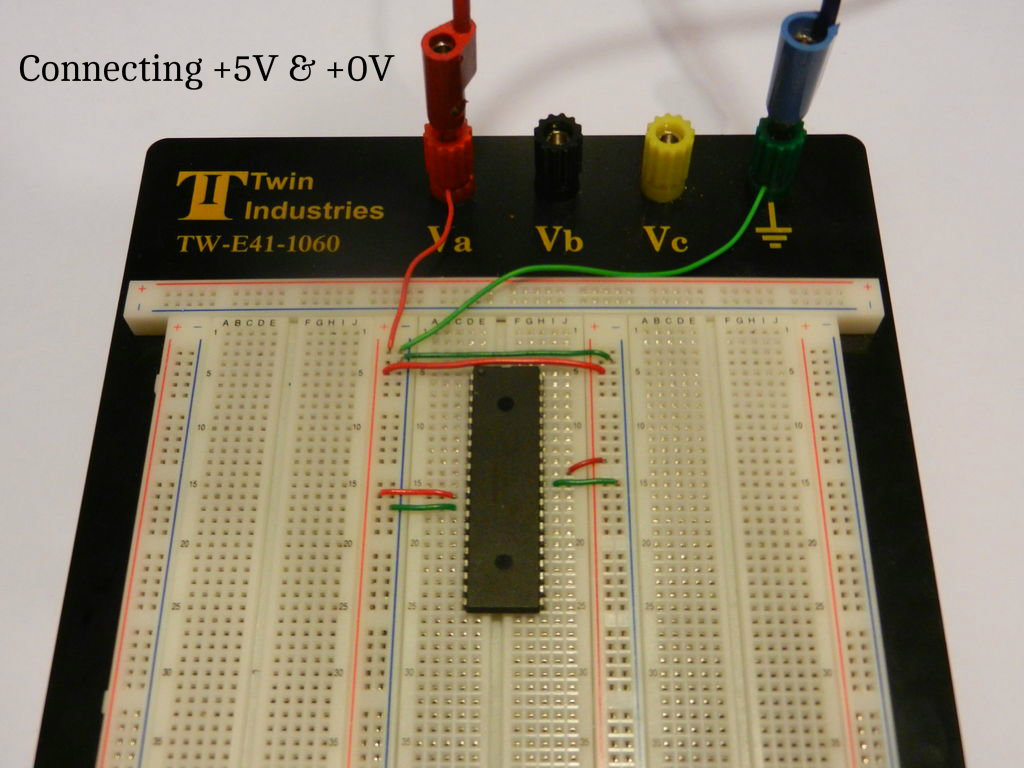
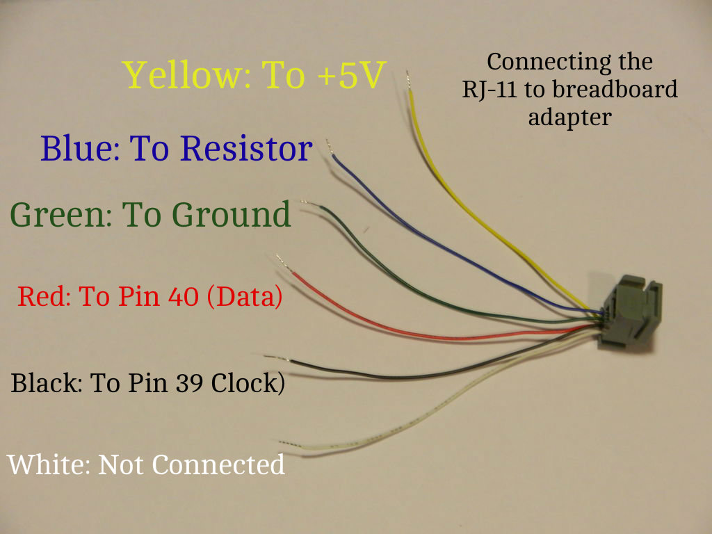
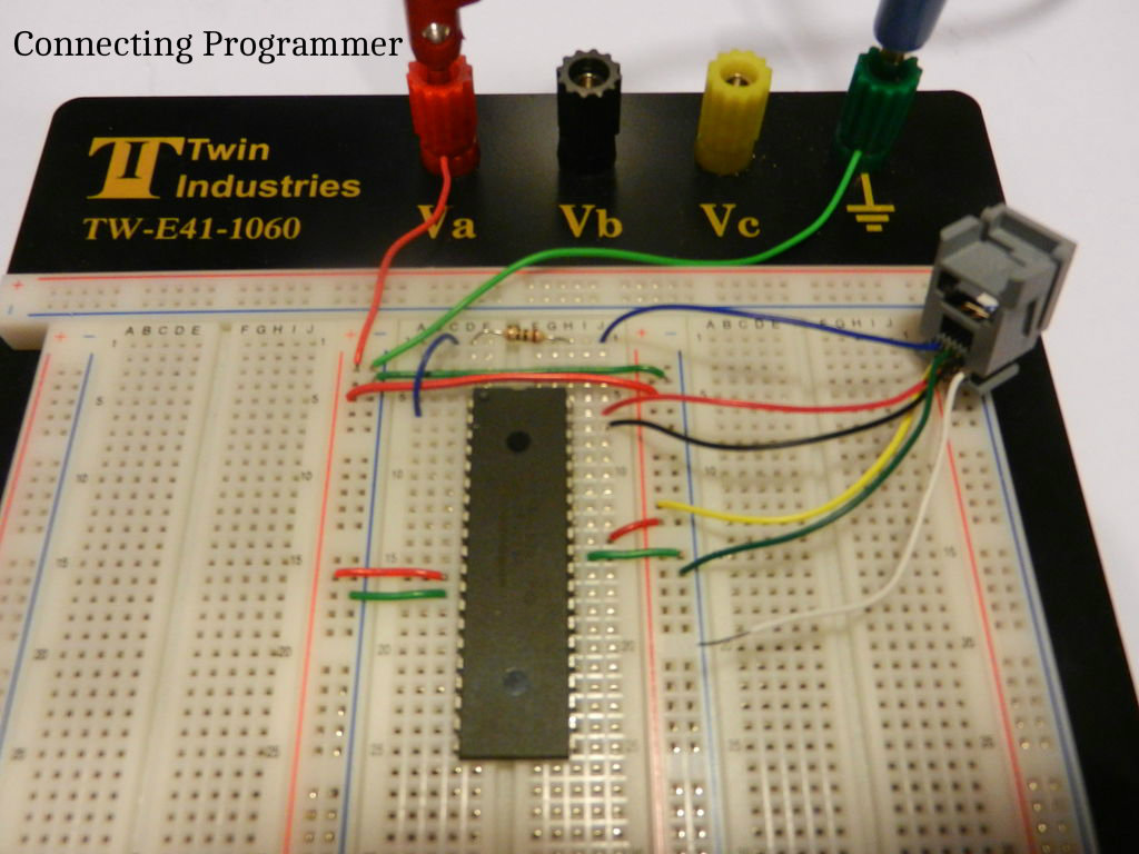
Note: The pictures provided above show the same connections mentioned below and help in interpreting the instructions below.
Pin Numbers: Figuring out where to connect +5V and +0V (Ground) is as easy as opening up this link (containing the datasheet) and scrolling down to the fourth page: http://microchip.com/downloads/en/DeviceDoc/39631E.... There you'll find that the following connections need to be made:
Pin 11 to +5V
Pin 12 to +0V
Pin 31 to +0V
Pin 32 to +5V
Pin 1 to one side of the 10Ohm Resistor (not mentioned in datasheet)
Additionally, the following connections need to be made with the RJ-11 to breadboard adapter (hereafter referred to as RJ-11 Adapter). The picture of the adapter associated with this step also shows what to connect.
RJ-11 Adapter Yellow Wire: To +5V
RJ-11 Adapter Blue Wire: To the other side of the 10Ohm Resistor
RJ-11 Adapter: Green Wire: To +0V
RJ-11 Adapter Red Wire: To Pin 40
RJ-11 Adapter Black Wire: To Pin 39
RJ-11 Adapter White Wire is NOT Connected
As a rule of thumb you can remember that integrated circuit chips start with pin 1 at the top left hand corner and finish by moving down the left side, then back up the highest numbered pin (top right corner). To tell the top from the bottom there is usually an indent or dot on the top side of the chip.
Also note that VDD = +5V and VSS = +0V (ground)
Encoder Setup
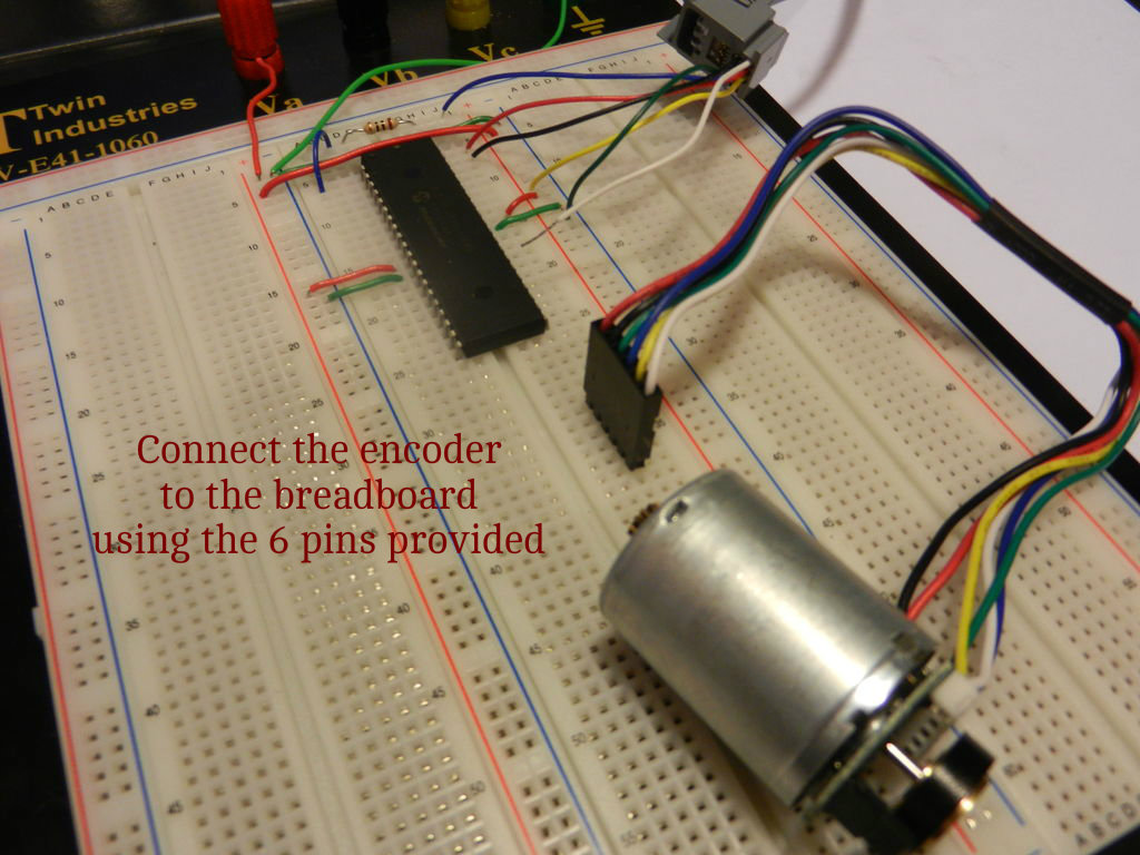
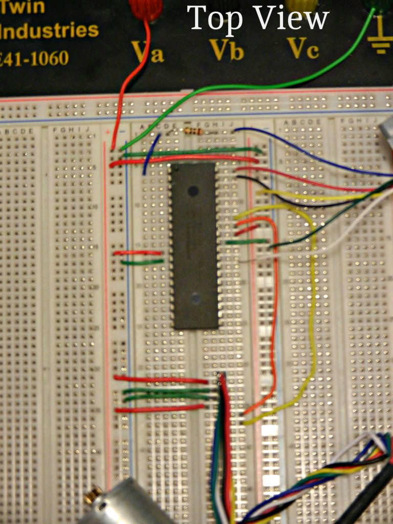
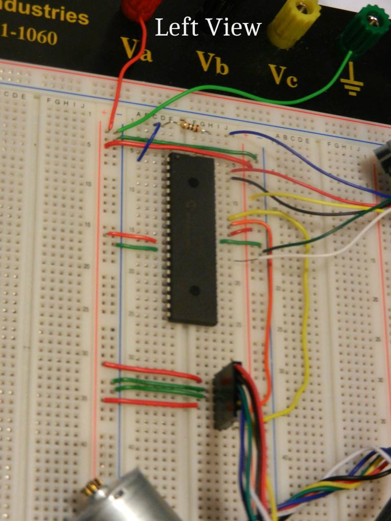
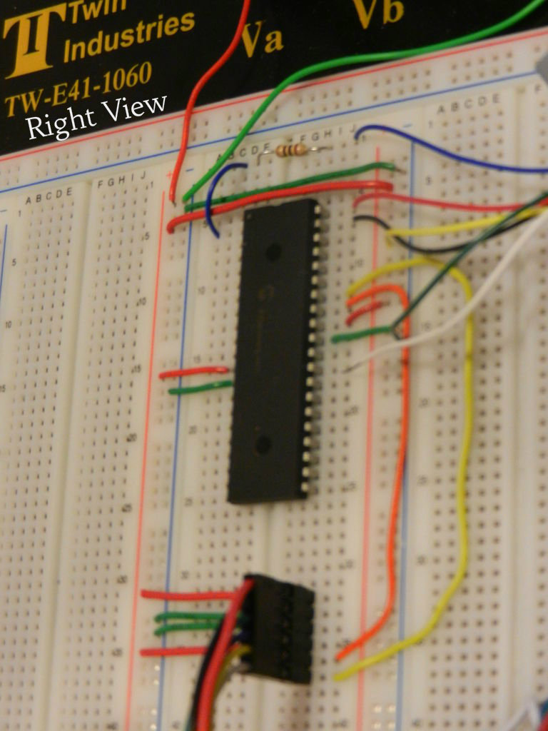
Circuit Connection: The motor & encoder require the connections listed below. Three pictures, each with a different view on the circuit, are included to aid in the encoder connection process.
Red Wire: To +5V
Black Wire: To +0V
Green Wire: To +0V
Blue Wire: To +5V
Yellow Wire: To Pin 33 (on microcontroller)
White Wire: To Pin 34 (on microcontroller)
You may wish to connect the red wire only when testing the motor since the current configuration would keep the motor running constantly. Alternatively, a motor driver can be used to turn the motor on and off (not covered in this tutorial).
Programming Setup
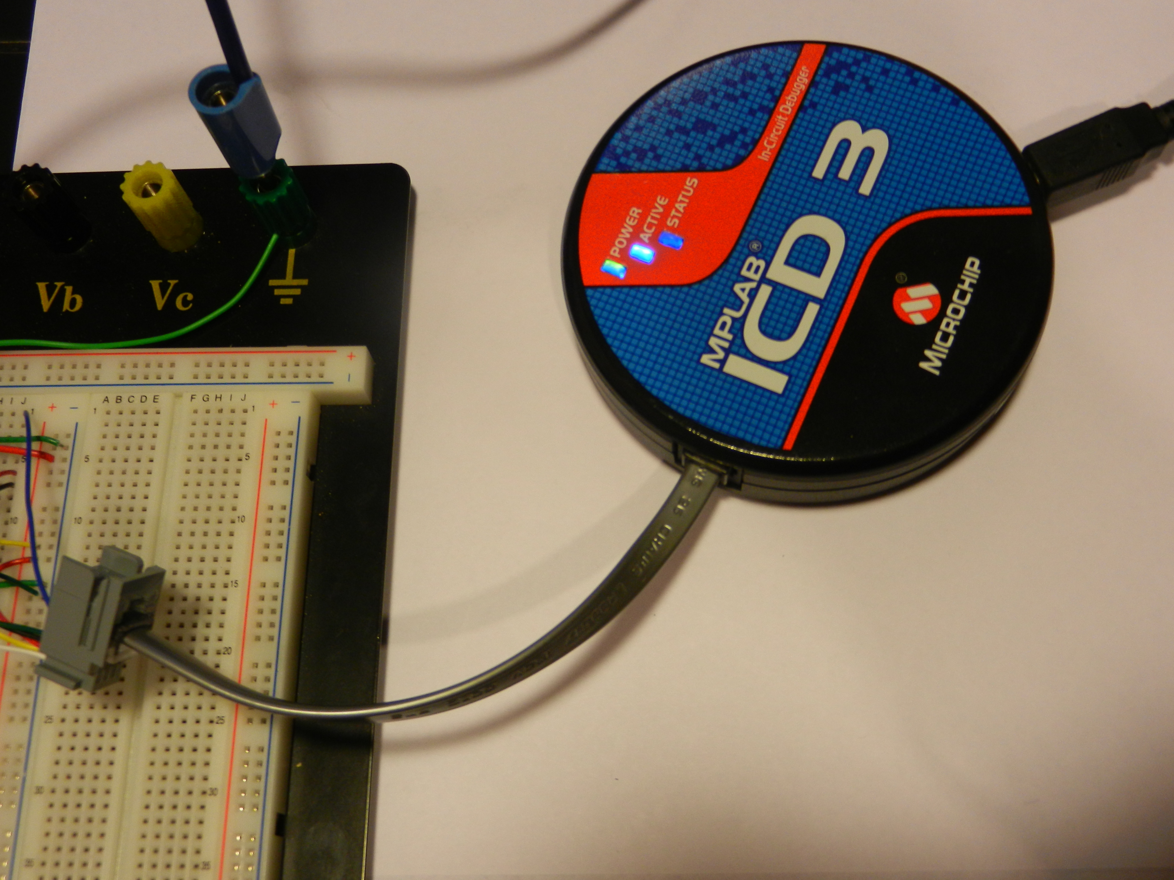
MPLAB X Configuration: At this point, we're ready to open MPLAB X and setup our project. See the steps below:
File>New Project>Standalone Project
Select Device: PIC18F4520
Select Hardware Tool: ICD3
Select Compiler: XC8
Name and save your project
Note: If you encounter any difficulty with these instructions selecting 'Quick Start' from the start page opens a webpage which will take you through the same steps with images. We are only concerned with the first five steps featured on that page for the purposes of this project.
Programming
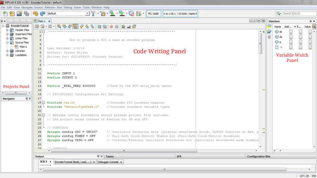
At this point, we'll be working exclusively with the MPLAB X IDE. To get started, notice the panel titled Projects on the left side of the MPLAB IDE window. From this panel, create a code:
Right-click on the 'Source Files' folder listed below your project>New>C Main File
Feel free to name it as you wish ('Main' is fine) You'll now see that MPLAB X has created a main file, visible in the center panel.
Code: For the purposes of this tutorial I will provide the necessary code, which you can copy and paste into that center window (after deleting all other text in the file) To give you an idea of what the code is doing, I've included a brief overview below as well as comments within the actual code itself (pasted below)
Overview: There are a couple of distinct portions of code for programming a PIC microcontroller, which are outlined below.
Define Statements: Define statements allow programmers to use words that may mean something else to the computer. For example, we could define the word OFF to mean a binary '0'. Thus while we see the word off, making the code easier to understand, the computer reads a binary '0'.
Include Statements: Include statements tell the compiler to include various header files. These external files may consist of files that define input/output functions (stdlib.h), or a variety of standard C functions (stdio.h), etc.
Pragmas: Pragmas are used to set the configuration bits on the microcontroller which control aspects such as oscillator selection, code protection, etc. Feel free to check out the configuration bits be selecting Window>PIC Memory Views>Configuration Bits
Functions: Functions are sections of the program that perform specific tasks. The main function is where the program starts execution.
Program:
/********************************************************************
How to program a PIC & read an encoder program
Last Revised: 1/3/14
Authors: Carson Miller
Written for: PIC18F4525 (Current Version)
*********************************************************************/
#define INPUT 1
#define OUTPUT 0
#define _XTAL_FREQ 4000000 //Used by the XC8 delay_ms(x) macro
// PIC18F25K22 Configuration Bit Settings
#include <xc.h> //Includes PIC hardware mapping
#include "GenericTypeDefs.h" //Includes standard variable types
// #pragma config statements should precede project file includes.
// Use project enums instead of #define for ON and OFF.
// CONFIG1H
#pragma config OSC = INTIO7 // Oscillator Selection bits (Internal oscillator block, CLKOUT function on RA6, port function on RA7)
#pragma config FCMEN = OFF // Fail-Safe Clock Monitor Enable bit (Fail-Safe Clock Monitor disabled)
#pragma config IESO = OFF // Internal/External Oscillator Switchover bit (Oscillator Switchover mode disabled)
// CONFIG2L
#pragma config PWRT = OFF // Power-up Timer Enable bit (PWRT disabled)
#pragma config BOREN = SBORDIS // Brown-out Reset Enable bits (Brown-out Reset enabled in hardware only (SBOREN is disabled))
#pragma config BORV = 3 // Brown Out Reset Voltage bits (Minimum setting)
// CONFIG2H
#pragma config WDT = OFF // Watchdog Timer Enable bit (WDT enabled)
#pragma config WDTPS = 32768 // Watchdog Timer Postscale Select bits (1:32768)
// CONFIG3H
#pragma config CCP2MX = PORTC // CCP2 MUX bit (CCP2 input/output is multiplexed with RC1)
#pragma config PBADEN = ON // PORTB A/D Enable bit (PORTB<4:0> pins are configured as analog input channels on Reset)
#pragma config LPT1OSC = OFF // Low-Power Timer1 Oscillator Enable bit (Timer1 configured for higher power operation)
#pragma config MCLRE = ON // MCLR Pin Enable bit (MCLR pin enabled; RE3 input pin disabled)
// CONFIG4L
#pragma config STVREN = ON // Stack Full/Underflow Reset Enable bit (Stack full/underflow will cause Reset)
#pragma config LVP = OFF // Single-Supply ICSP Enable bit (Single-Supply ICSP enabled)
#pragma config XINST = OFF // Extended Instruction Set Enable bit (Instruction set extension and Indexed Addressing mode disabled (Legacy mode))
// CONFIG5L
#pragma config CP0 = OFF // Code Protection bit (Block 0 (000800-003FFFh) not code-protected)
#pragma config CP1 = OFF // Code Protection bit (Block 1 (004000-007FFFh) not code-protected)
#pragma config CP2 = OFF // Code Protection bit (Block 2 (008000-00BFFFh) not code-protected)
// CONFIG5H
#pragma config CPB = OFF // Boot Block Code Protection bit (Boot block (000000-0007FFh) not code-protected)
#pragma config CPD = OFF // Data EEPROM Code Protection bit (Data EEPROM not code-protected)
// CONFIG6L
#pragma config WRT0 = OFF // Write Protection bit (Block 0 (000800-003FFFh) not write-protected)
#pragma config WRT1 = OFF // Write Protection bit (Block 1 (004000-007FFFh) not write-protected)
#pragma config WRT2 = OFF // Write Protection bit (Block 2 (008000-00BFFFh) not write-protected)
// CONFIG6H
#pragma config WRTC = OFF // Configuration Register Write Protection bit (Configuration registers (300000-3000FFh) not write-protected)
#pragma config WRTB = OFF // Boot Block Write Protection bit (Boot Block (000000-0007FFh) not write-protected)
#pragma config WRTD = OFF // Data EEPROM Write Protection bit (Data EEPROM not write-protected)
// CONFIG7L
#pragma config EBTR0 = OFF // Table Read Protection bit (Block 0 (000800-003FFFh) not protected from table reads executed in other blocks)
#pragma config EBTR1 = OFF // Table Read Protection bit (Block 1 (004000-007FFFh) not protected from table reads executed in other blocks)
#pragma config EBTR2 = OFF // Table Read Protection bit (Block 2 (008000-00BFFFh) not protected from table reads executed in other blocks)
// CONFIG7H
#pragma config EBTRB = OFF // Boot Block Table Read Protection bit (Boot Block (000000-0007FFh) not protected from table reads executed in other blocks)
//Dummy variable setup
UINT distance = 0;
CHAR direction = 0;
CHAR error = 0;
void configure(void)
{
//ADC Setup
ADCON1bits.PCFG = 1111; //Turns off all analog inputs (See datasheet p. 224)
//Oscillator Setup
OSCCONbits.IRCF = 110; //Sets oscillator to 4MHz
//Interrupt Setup
INTCONbits.GIE = 1; //Enables all unmasked or high priority interrupts (Depending on IPEN)
INTCONbits.PEIE = 1; //Enables all unmasked peripheral interrupts or low- priority interrupts (Depending on IPEN)
INTCONbits.INT0IF = 0; //Clears interrupt 0 flag bit (Must occur before enabling interrupt)
INTCONbits.INT0IE = 1; //Enables the INT0 external interrupt
INTCON2bits.INTEDG0 = 1; //Sets external interrupt 0 to interrupt on rising edge
RCONbits.IPEN = 0; //Disables priority levels on interrupts
TRISBbits.TRISB0 = INPUT; //Sets INT0 as input
TRISBbits.TRISB1 = INPUT; //Sets INT1 as input
}
void main()
{
configure();
while(1)
{
//Program Loop
}
}
//Main interrupt service routine (ISR)
void interrupt ISR()
{
//Check to see if it is interrupt 0
if (INTCONbits.INT0IF == 1)
{
distance++;
INTCONbits.INT0IF = 0; //Clears interrupt flag
}
else
error = 1;
}
Running the Program & Debugging
Checking the encoder value: To check the encoder value, you must add a variable 'watch' in the panel on the left side of the MPLAB IDE window. Simply click where it says 'Enter new watch' and type either direction or distance. You'll then be able to track those variables through that window. Note that the program must be paused to see the values in the variable watch change. Further, if the value in the variable watch shows up in an improper format, right click the incorrect value and hover over 'Display value column as' so that you can select the proper format.
Project Complete!
If you've reached the end and don't have a working project don't worry. There are a number of things to try:
Multimeter: Check to ensure that your microcontroller & motor/encoder are receiving +5V and +0V (ground) at the appropriate locations
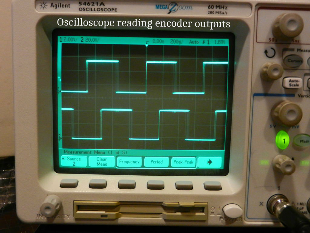
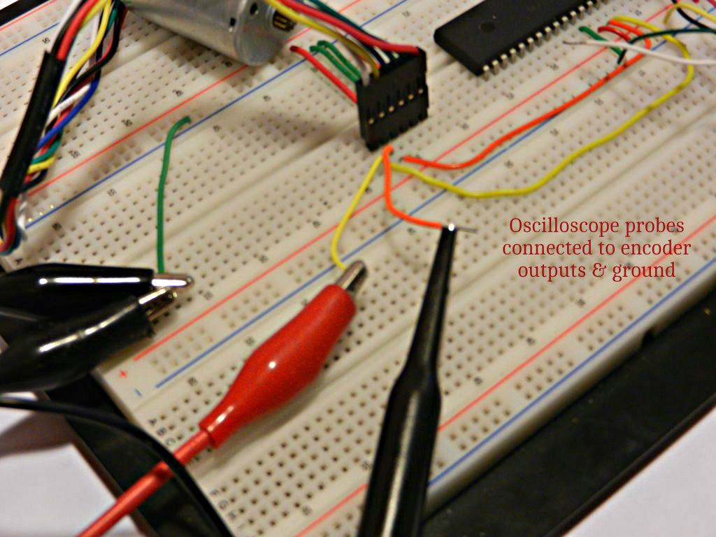
Oscilloscope: Check to ensure that your encoder is sending signals like those shown in the oscilloscope image associated with this step. The encoder should put out two square waves, from the yellow and white wires, that are 90 degrees out of phase.
MPLAB X: Check to ensure that your microcontroller is setup properly by making sure that your special function registers have the proper binary values (as set in the code from step 6). To see the special function registers go to Window>PIC Memory Views>SFRs after pausing during a debugging session. From there you can check to see that the pin with INT0 (pin 33) is set as an input, for example, by holding your cursor over the TRISB register.
Comments: If you're unable to solve the problem or have questions/comments about this tutorial please leave a response in the comments section and I will happily respond.