How to Program a ATtiny With Arduino
by lonesoulsurfer in Circuits > Arduino
7922 Views, 20 Favorites, 0 Comments
How to Program a ATtiny With Arduino

Learn how to program a ATtiny using an Arduino!
I put this instructable together as I didn't find anything on the net that had the complete instructions on how to program a ATtiny. There are a couple of good instructions available but I found that they forgot a couple steps which just made things confusing.
I'm far for being an expert when it comes to this type of thing but I did manage to work it out and so I thought I'd share the instructions with the world.
It's actually quite easy to be able to program ATtiny's using an Arduino - when you have the right instructions!
The following 'Ible takes you through step by step exactly what you need to to be able to program ATtiny chips.
WAIT! - the development board I built in for this project was a little rough and ready (although works fine). I decided to build a more permanent one which you can find here: https://www.instructables.com/Programmer-for-ATtiny-85/
Let's get started
Supplies
PARTS:
Hardware
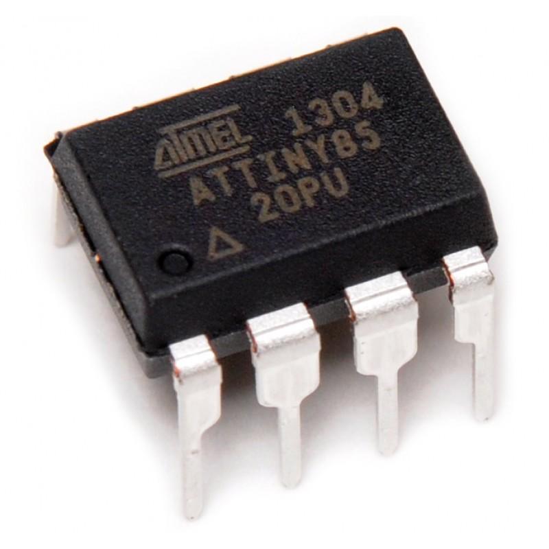
- ATtiny - There are many types but in this Ible' I'll be using a ATtiny 85 which is a pretty popular one - Ali Express
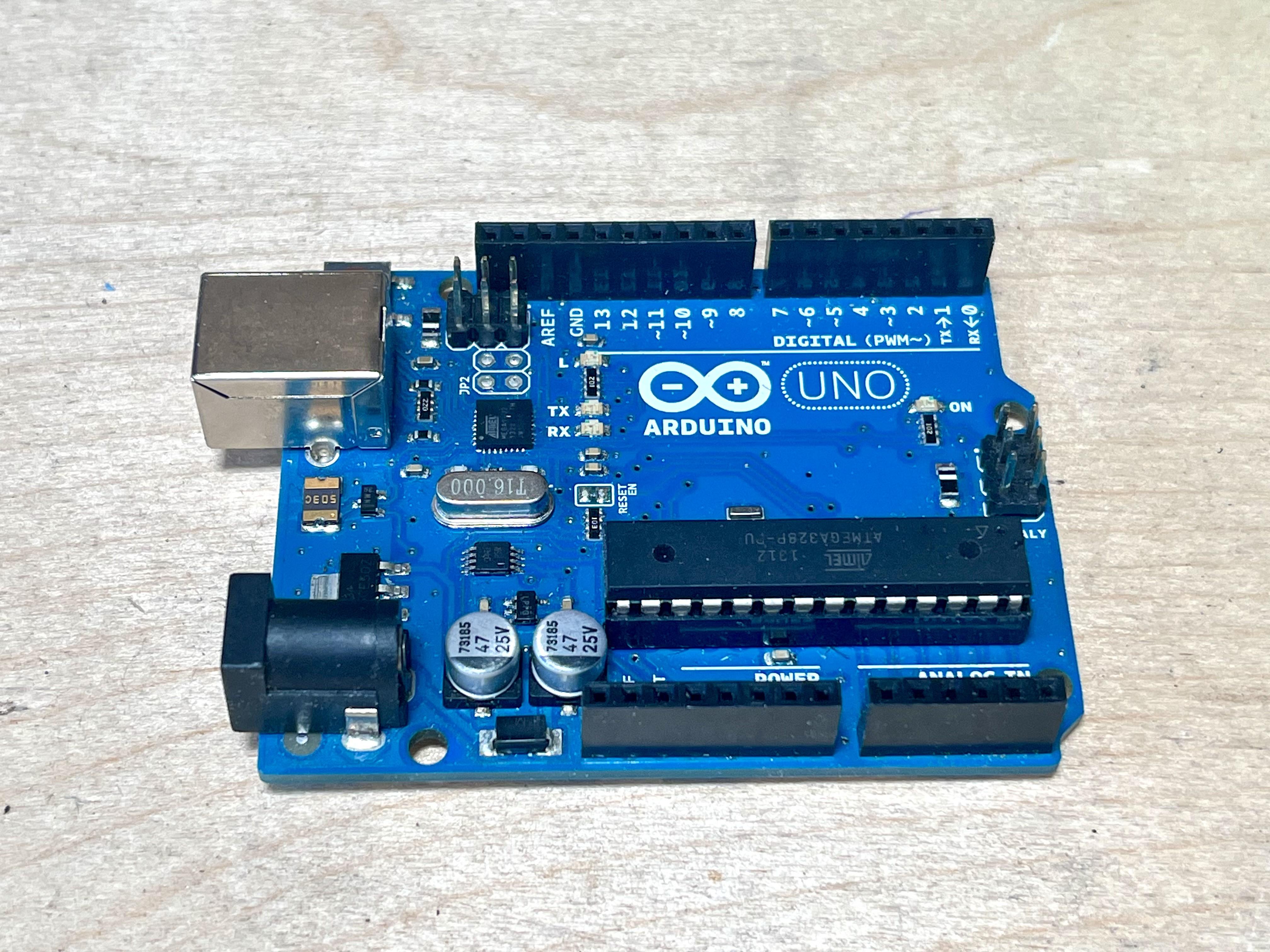
- Arduino Uno. Prob could use other Arduino's but this is what I used - Ali Express
- Arduino USB 2.0 CABLE TYPE A/MICRO. This is what you use to connect the Arduino to the PC - Ali Express
Additional Parts
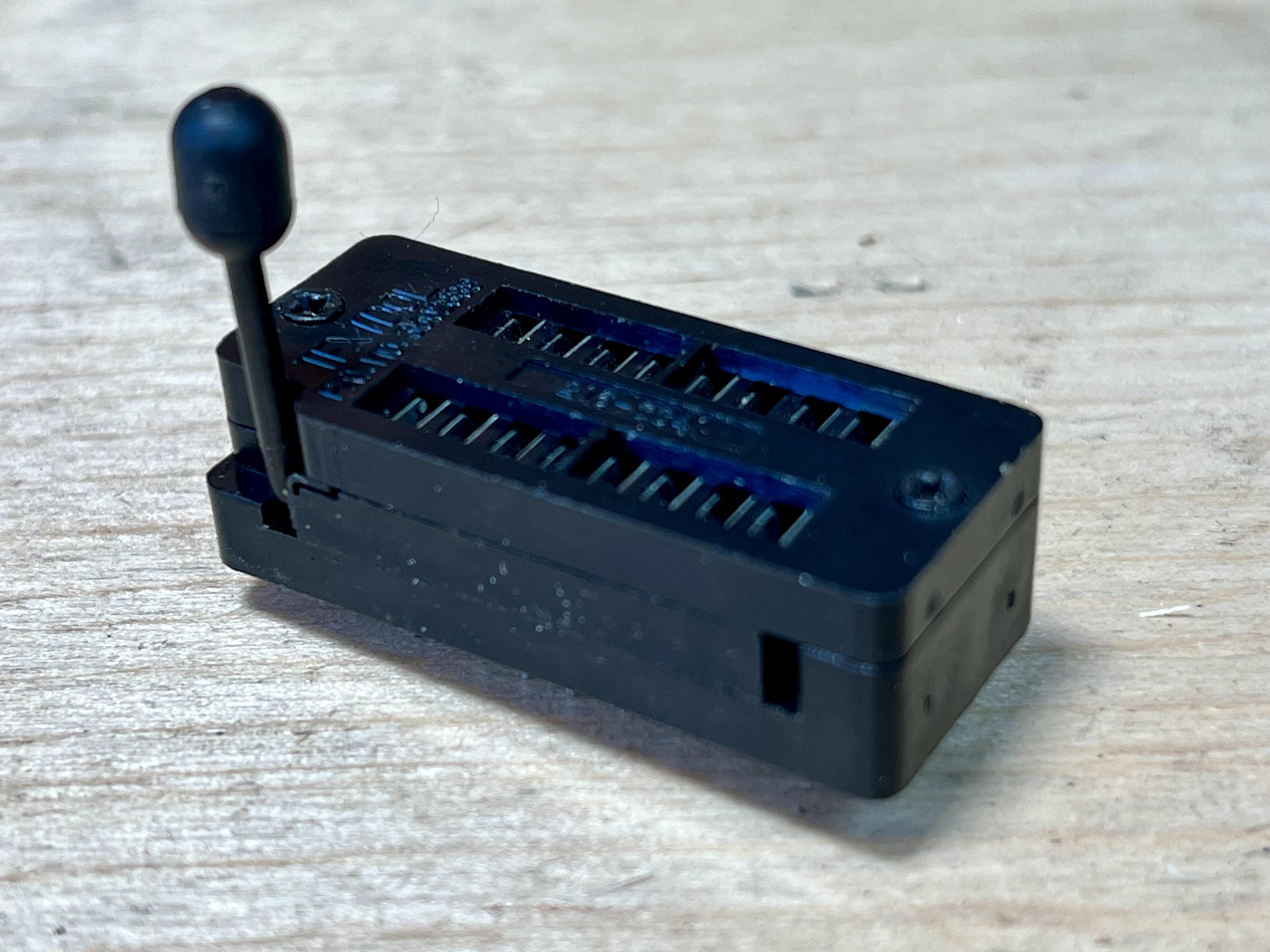
- 16 Pin ZIF Test DIP IC - Ali Express
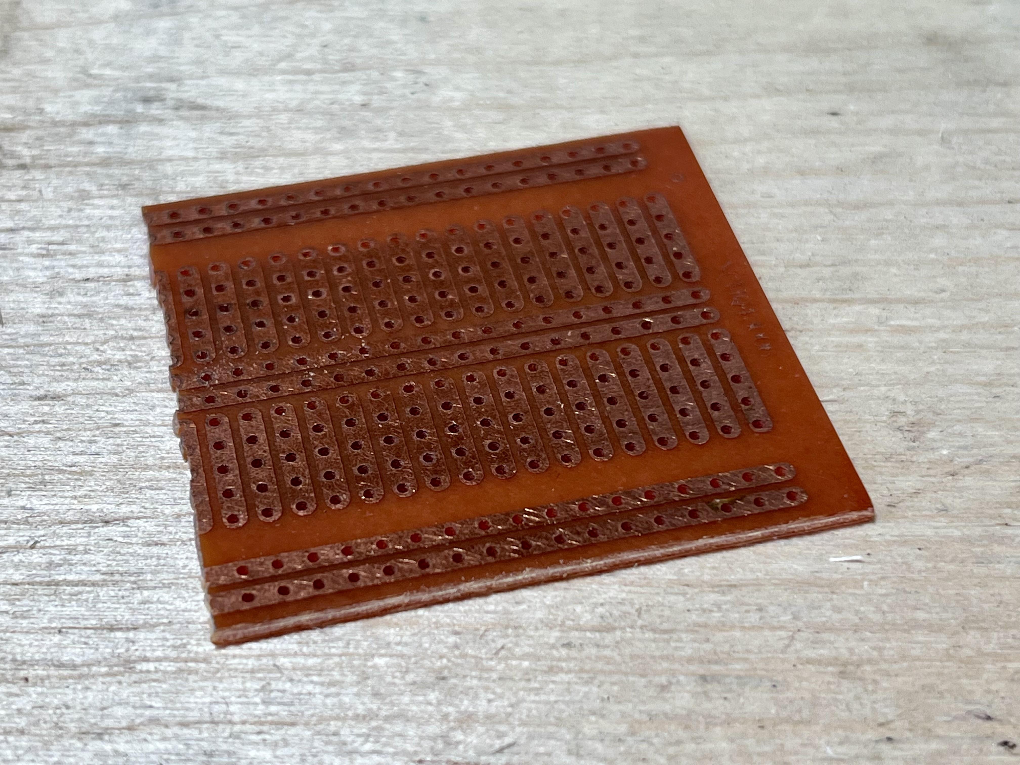
- Prototype board - Ali Express
- Male to male jumper wires - Ali Express
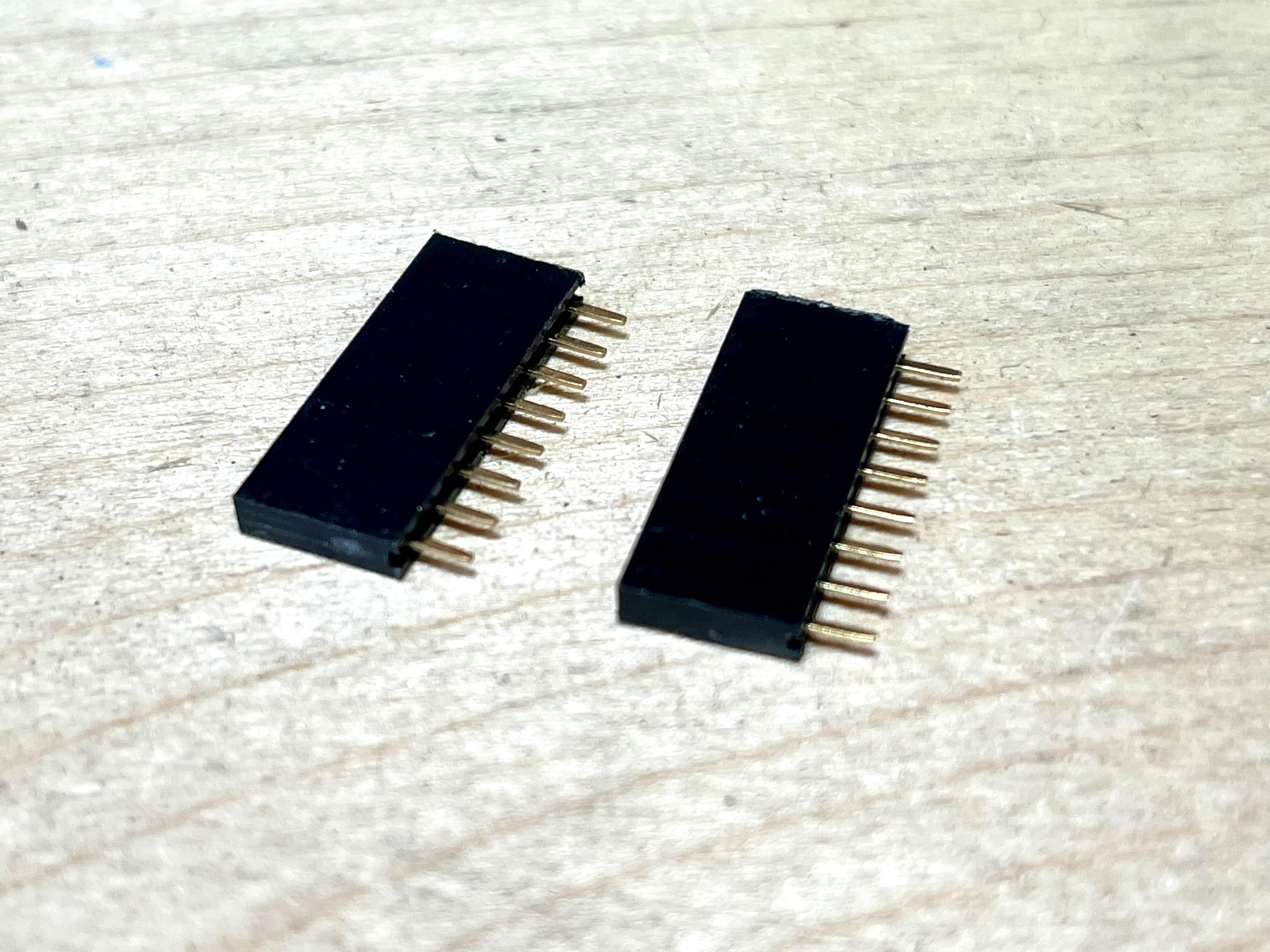
- Female 8 Pin sockets - Ali Express
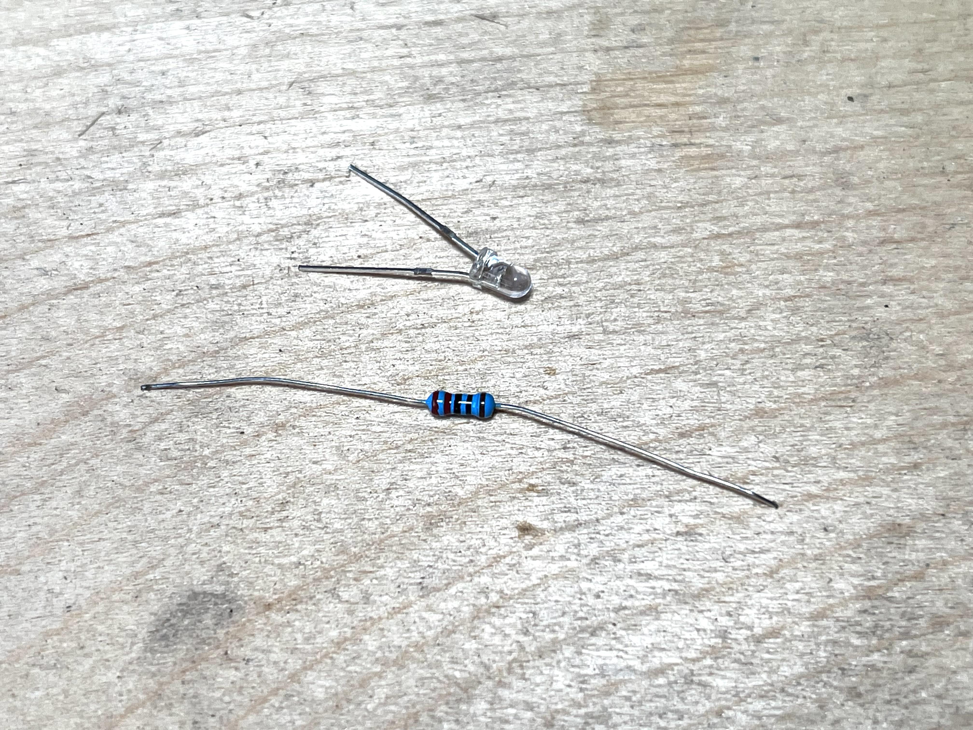
- 220R Resistor - Ali Express
- LED - Red 3mm - Ali Express
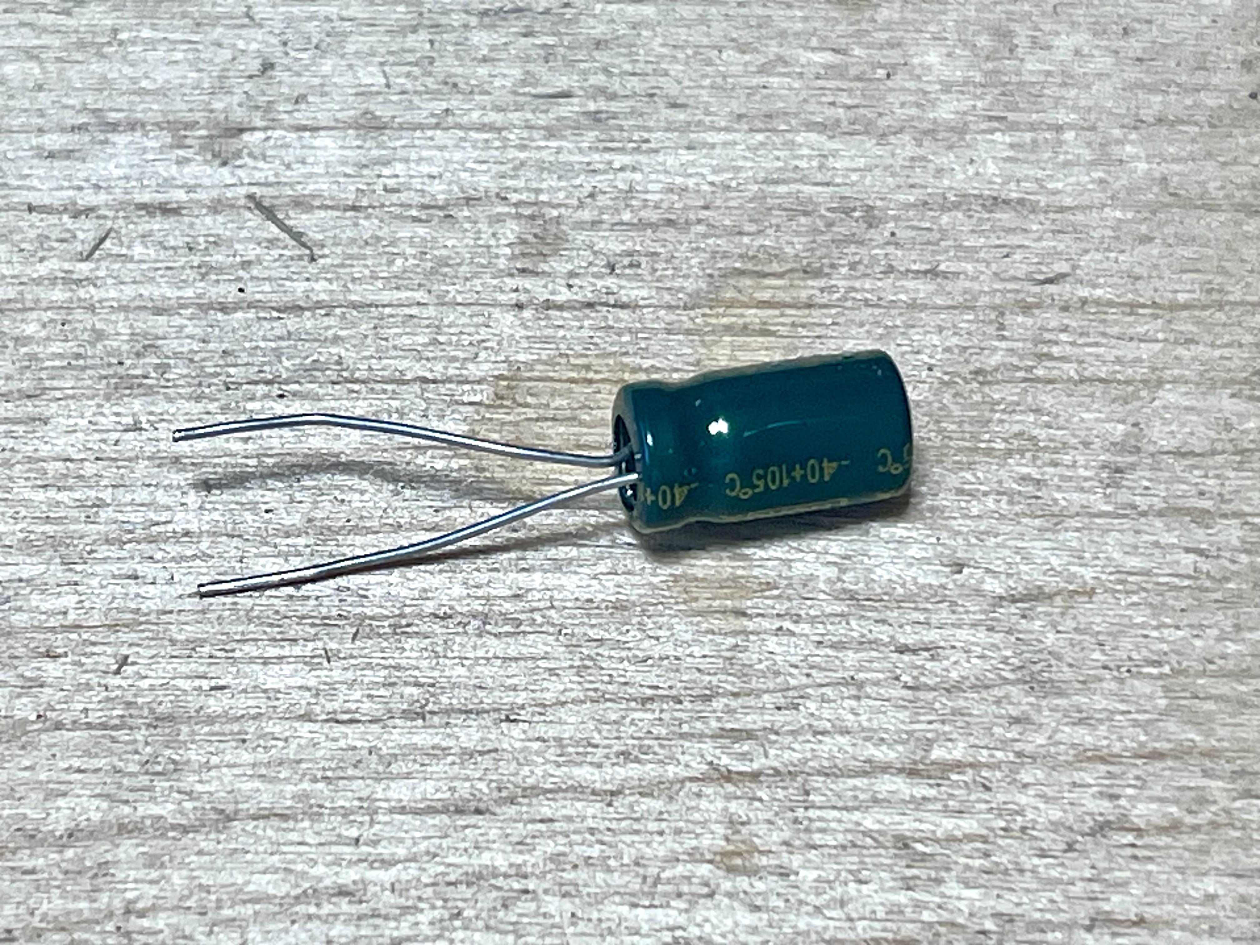
- 10uf Capacitor - Ali Express
- Small piece of ply wood (forms the base to attached the Arduino and prototype board to)
Creating a Development Board for the ATtiny

If you wanted to you could just use a breadboard for this part. However, I wanted something more permanent so I made a little development board to plug in the ATtiny to.
STEPS:
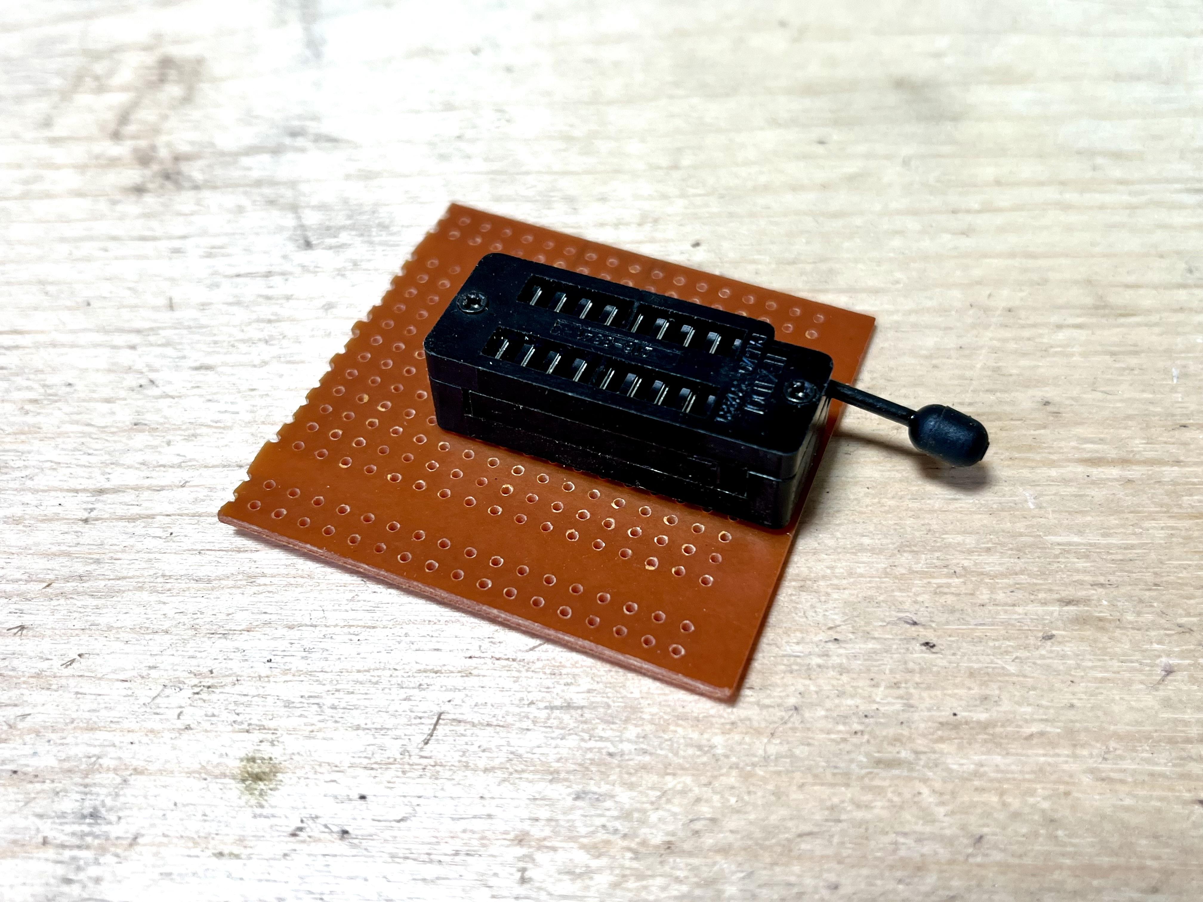
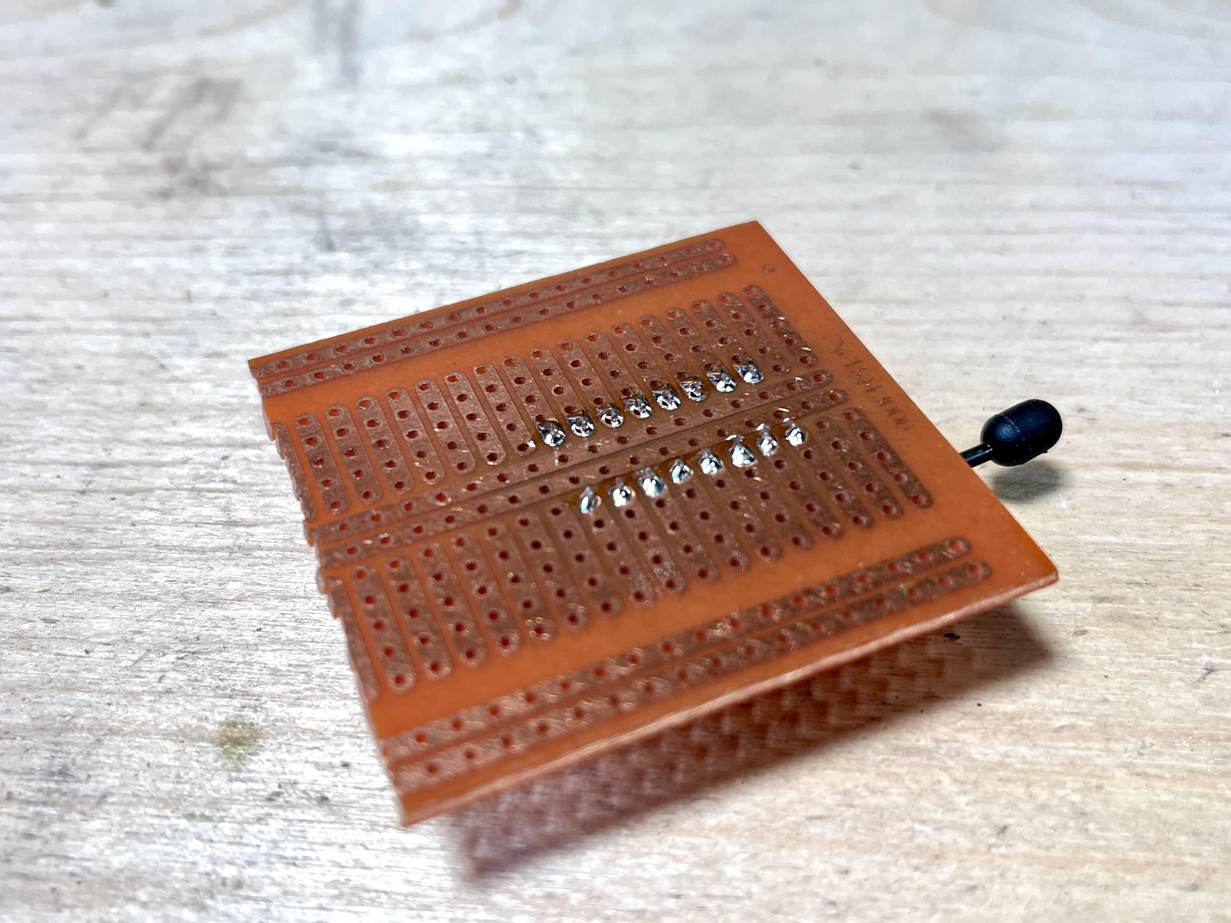
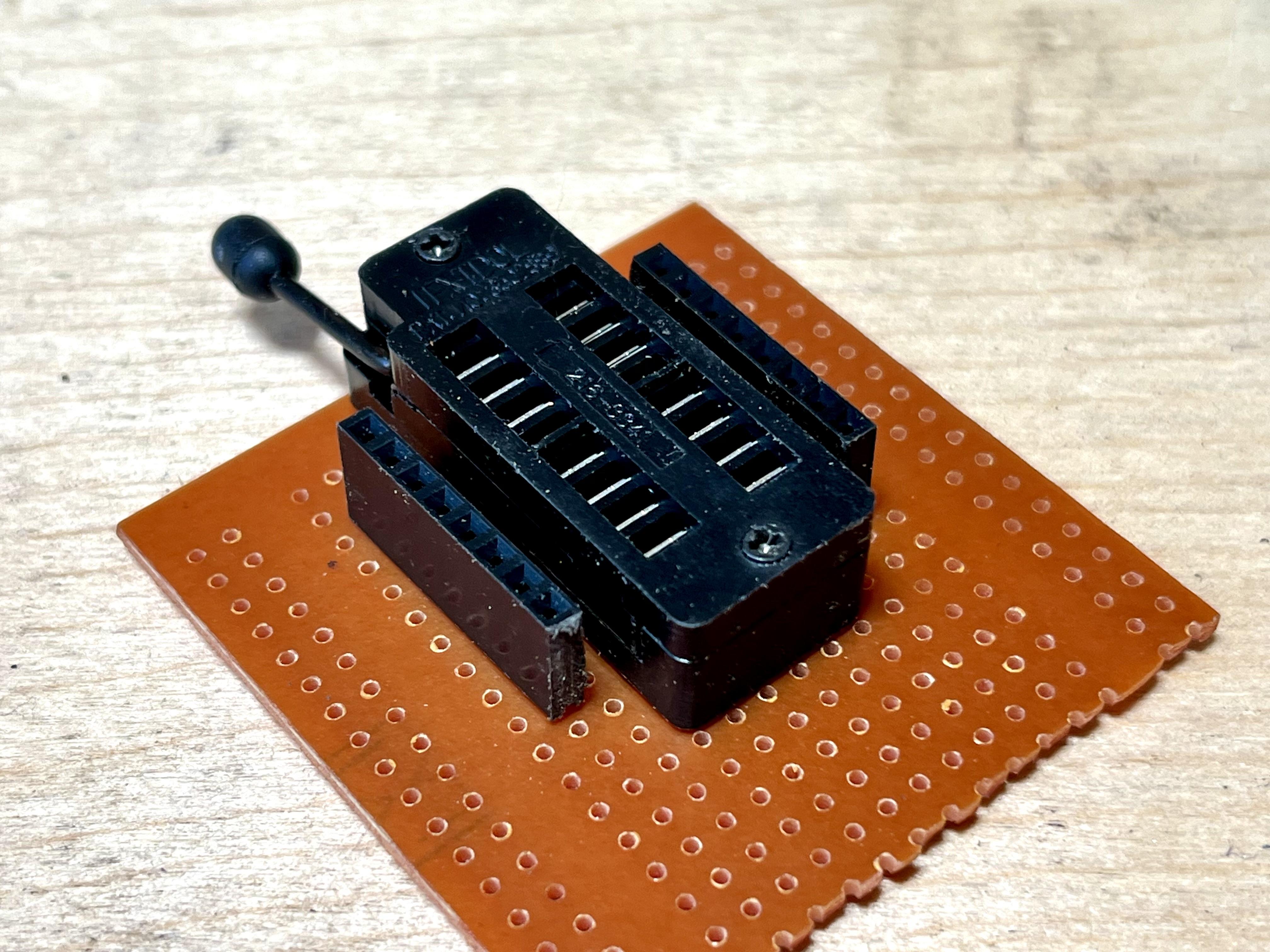
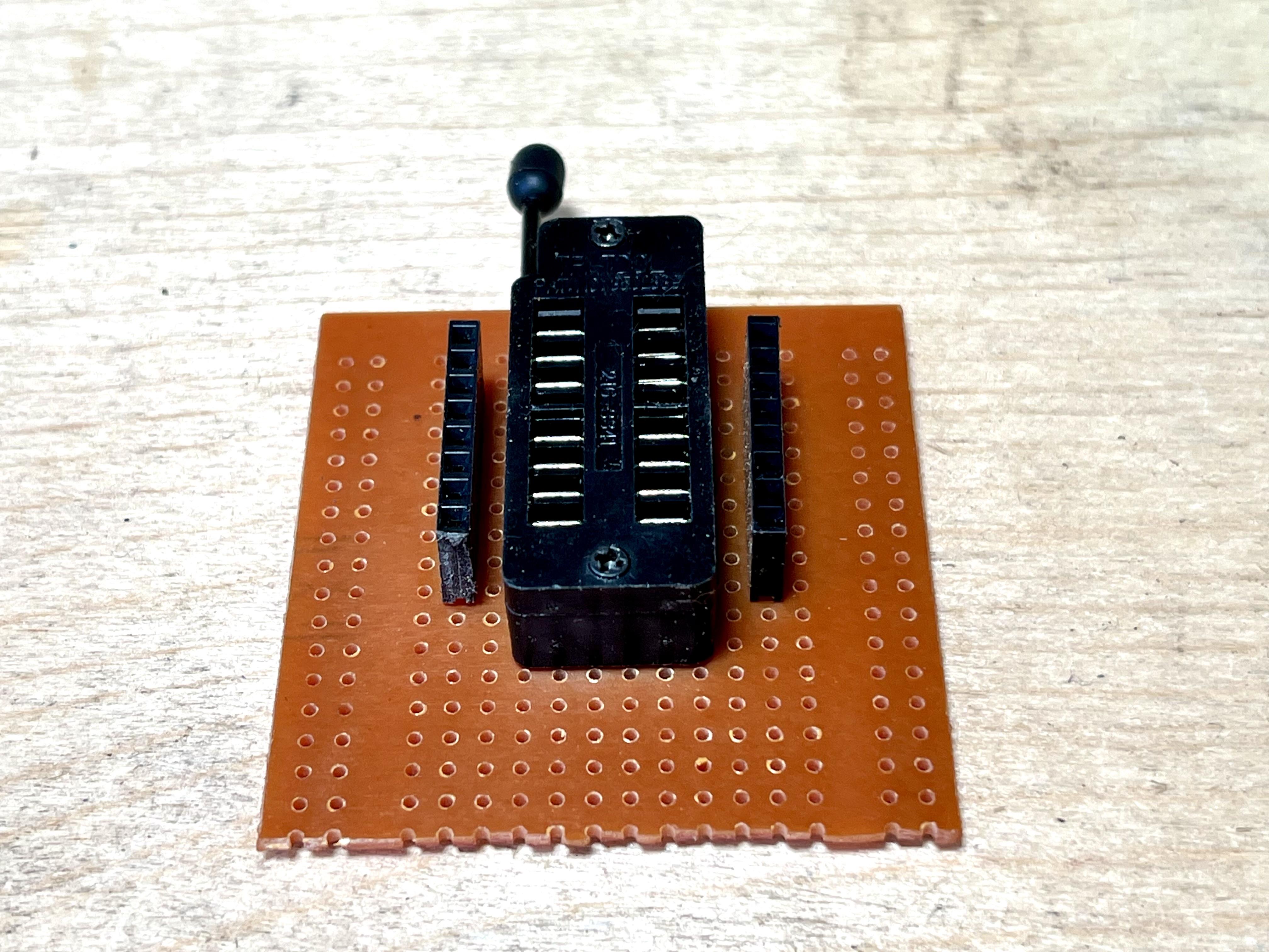
- Solder the 16 Pin ZIF Test IC to to the prototype board
- Next, add the 8 pin female header to the board and align them to the pins on the ZIF test IC
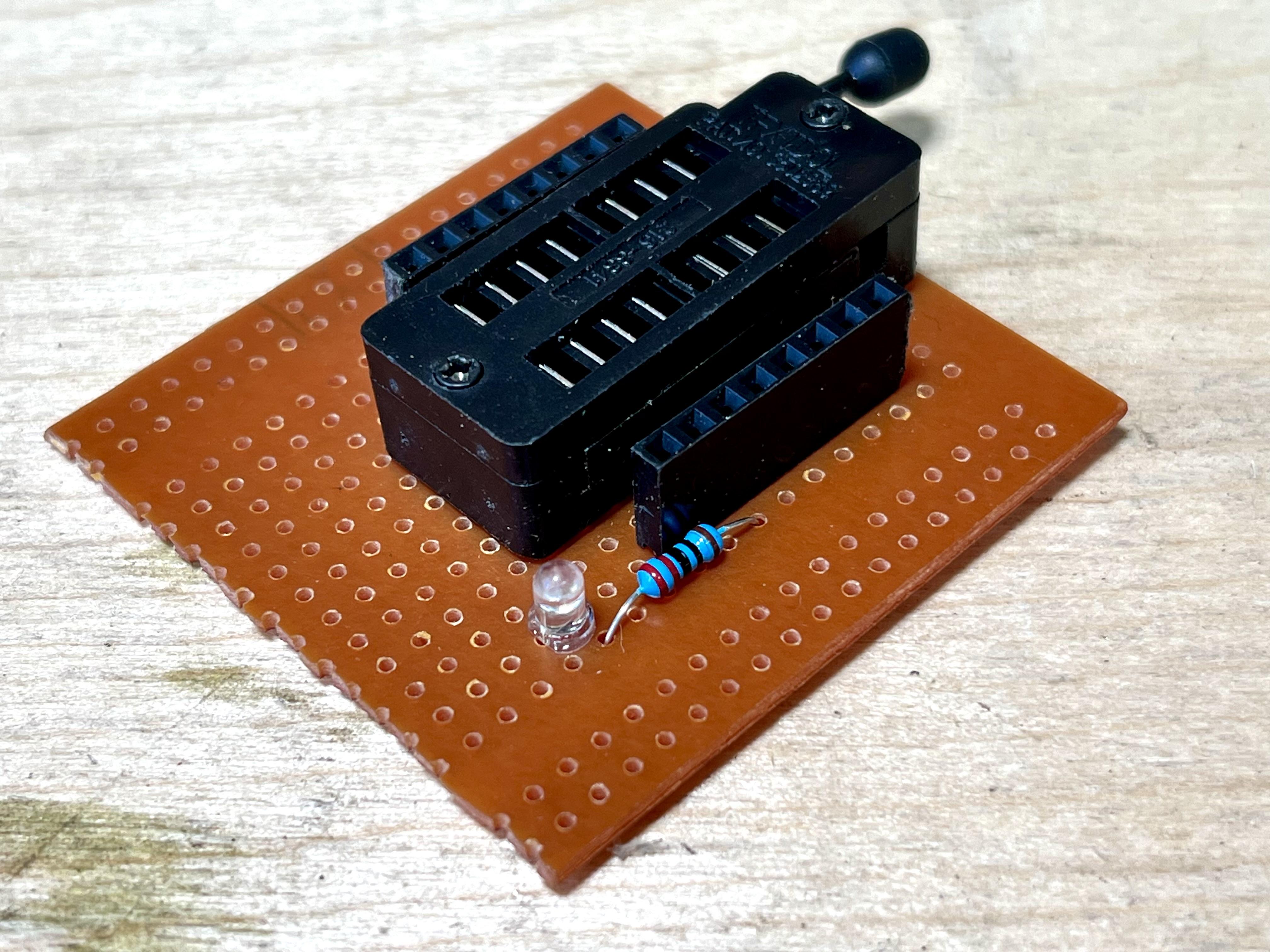
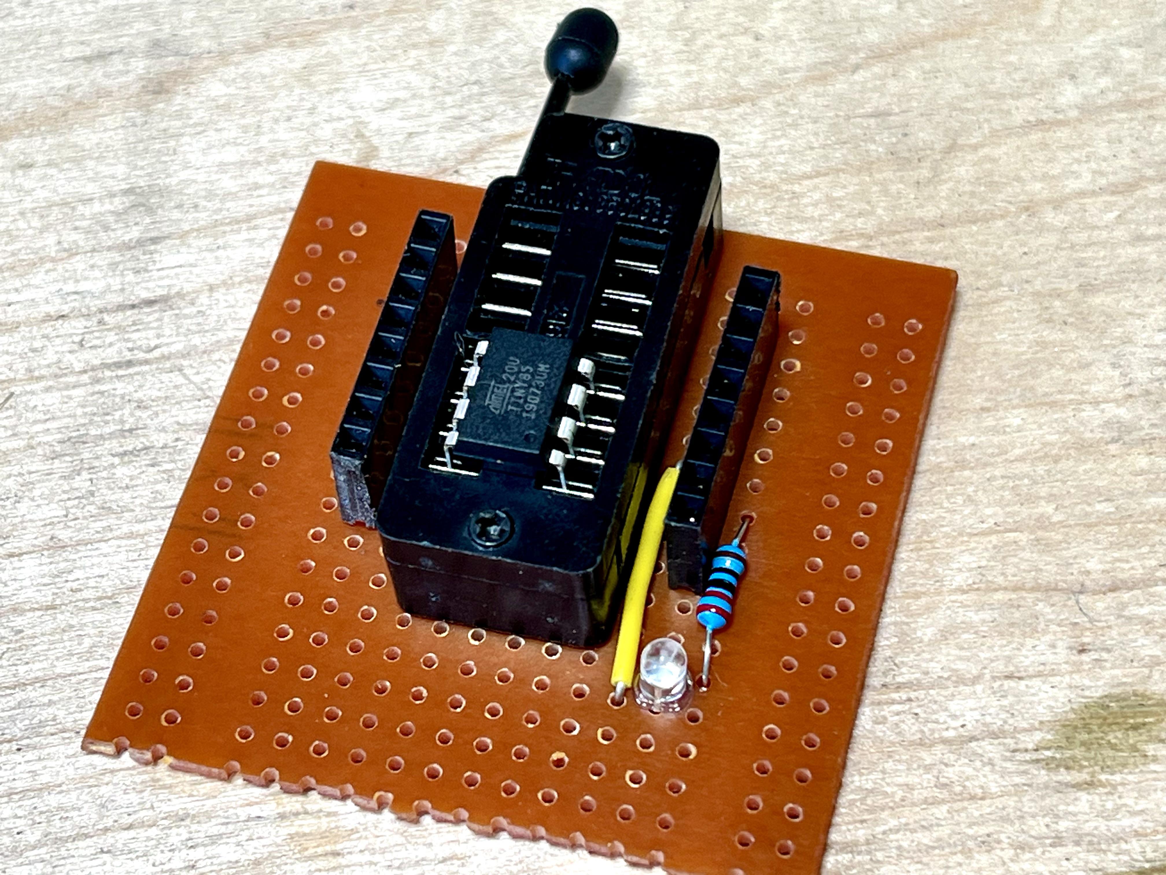
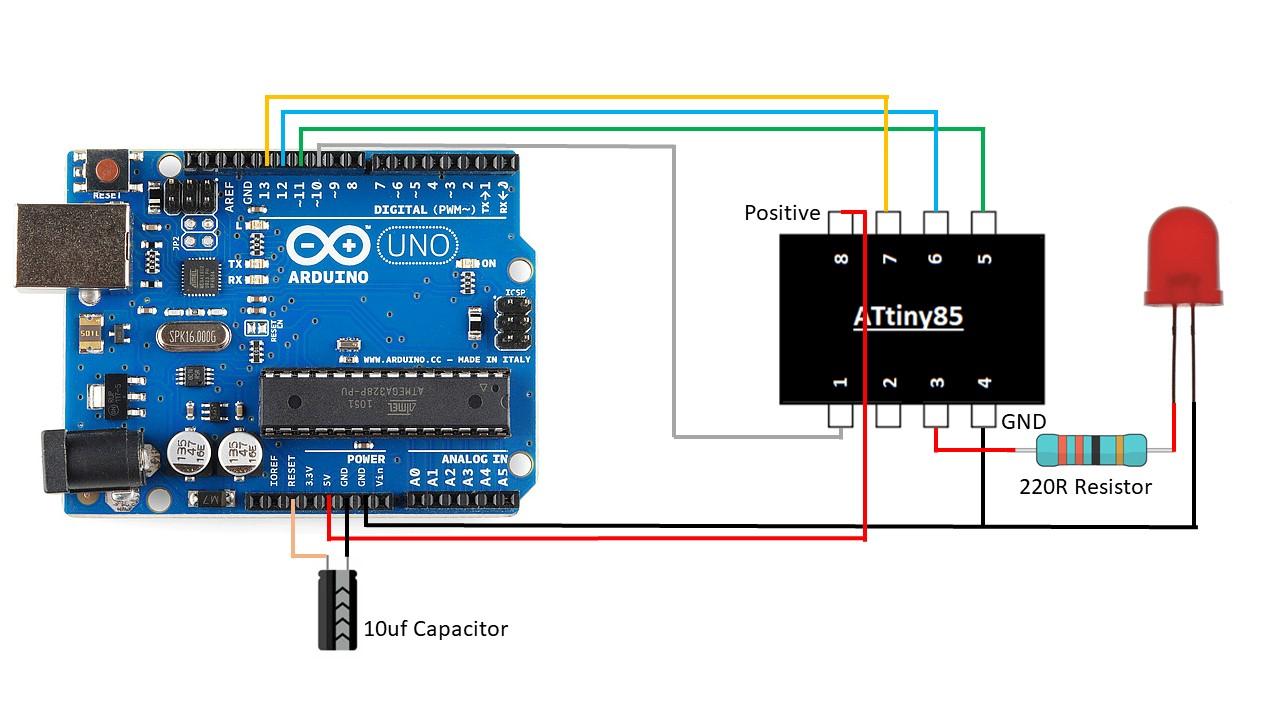
- To be able to run the 'blink test' I decided to also connect he LED and resistor straight to the prototype board. Check out the wire diagram in the image to see how to connect these parts together
- Cathode (Ground Leg) - Pin 4
- Anode (positive) connect one side to a 220R resistor and the other leg of the resistor to pin 3
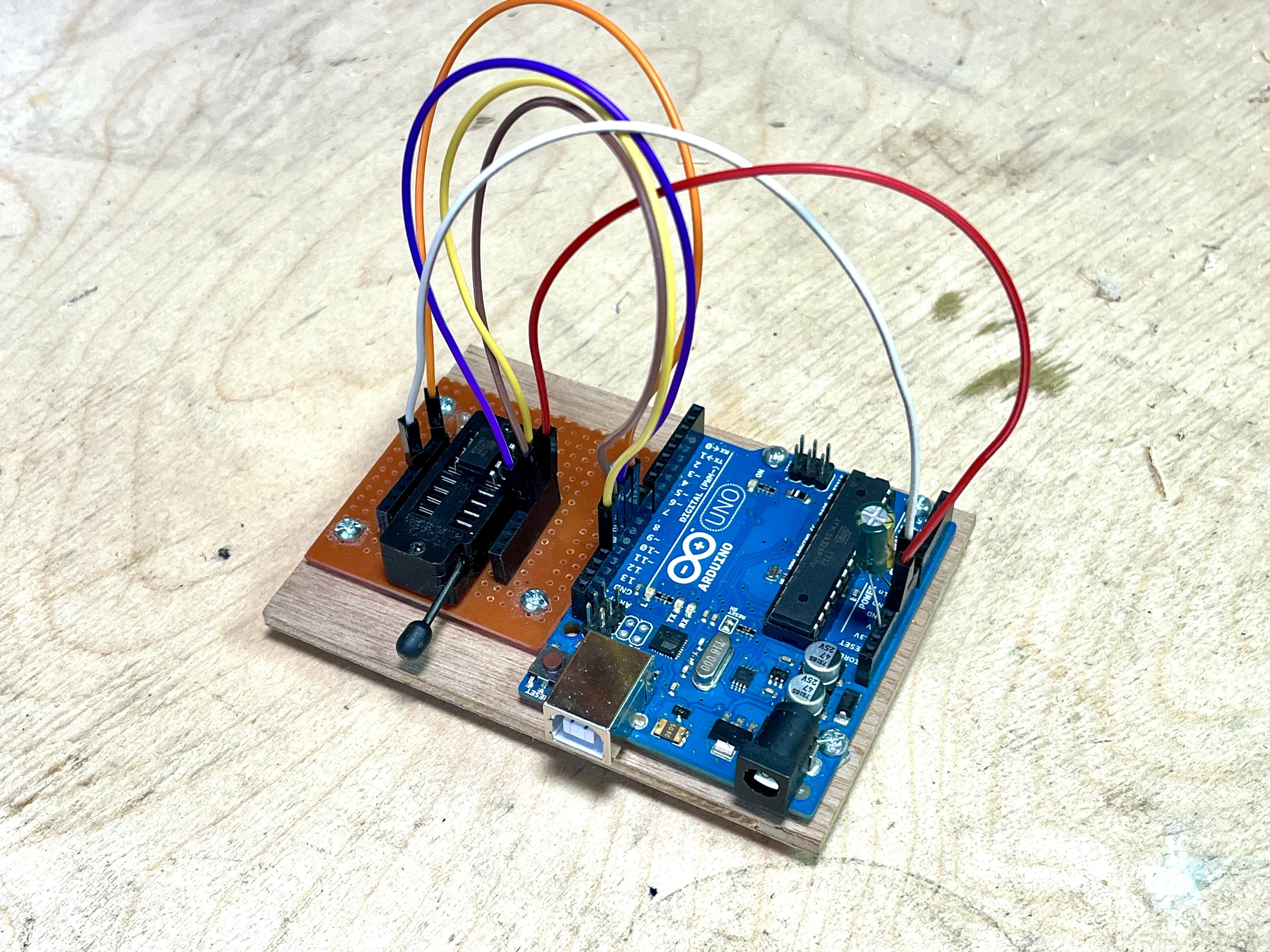
Connecting the Development Board to the Arduino
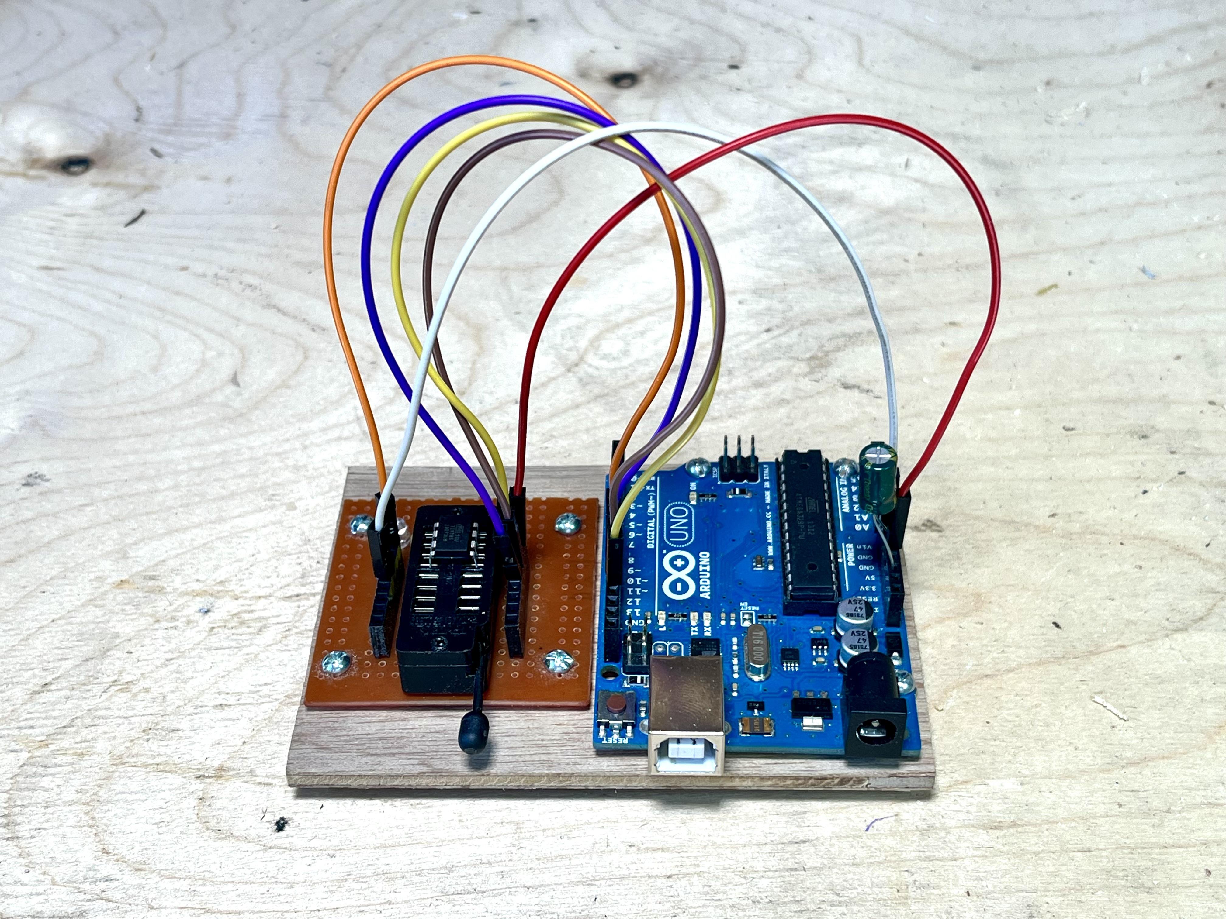
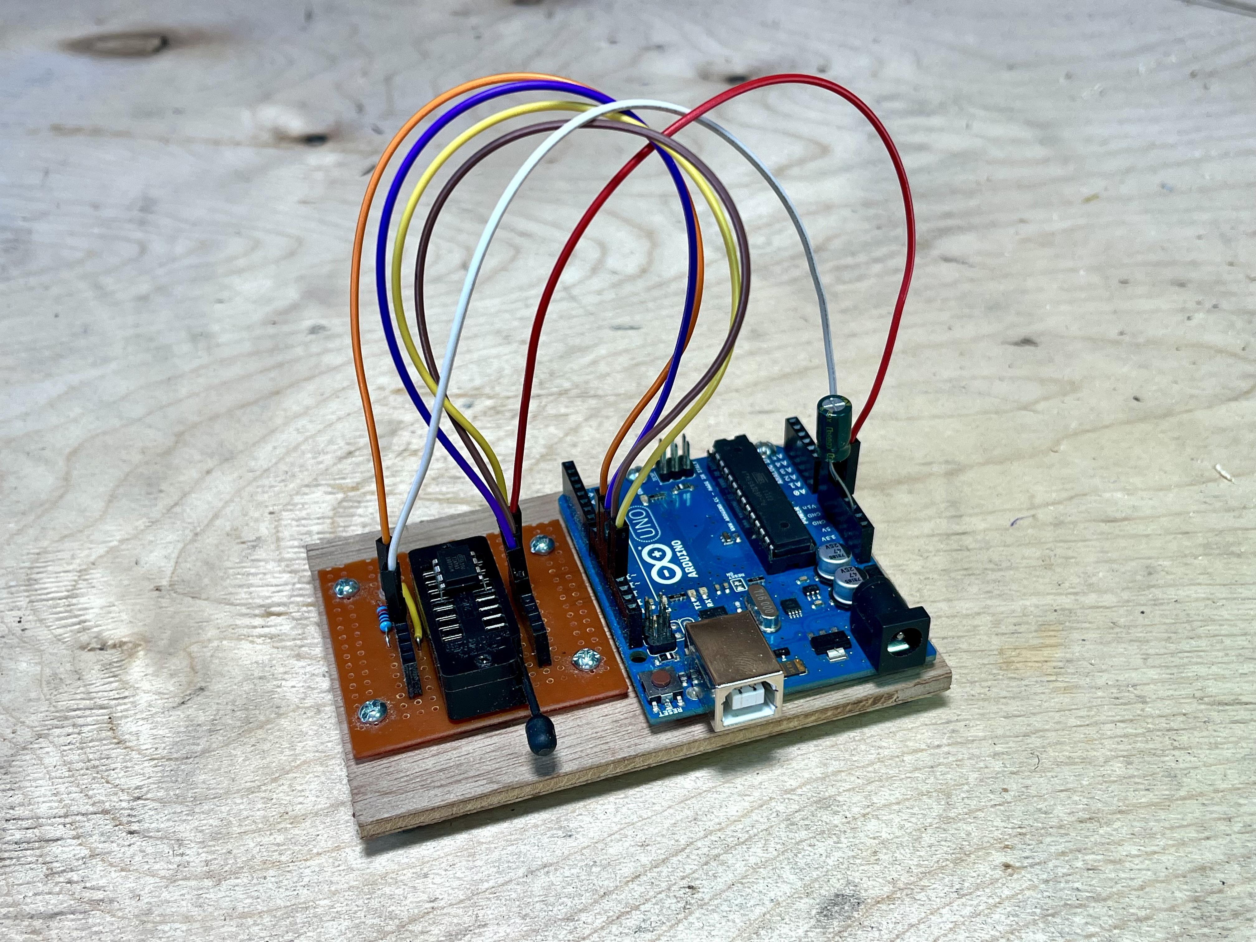
I wanted to have the development board and Arduino permanently together so I added them to a small piece of ply wood.
STEPS:
- Cut a small piece of plywood so it fits the Arduino and development board on it
- Place the Arduino onto the ply wood, mark and drill some holes where the mounting holes are on the Arduino
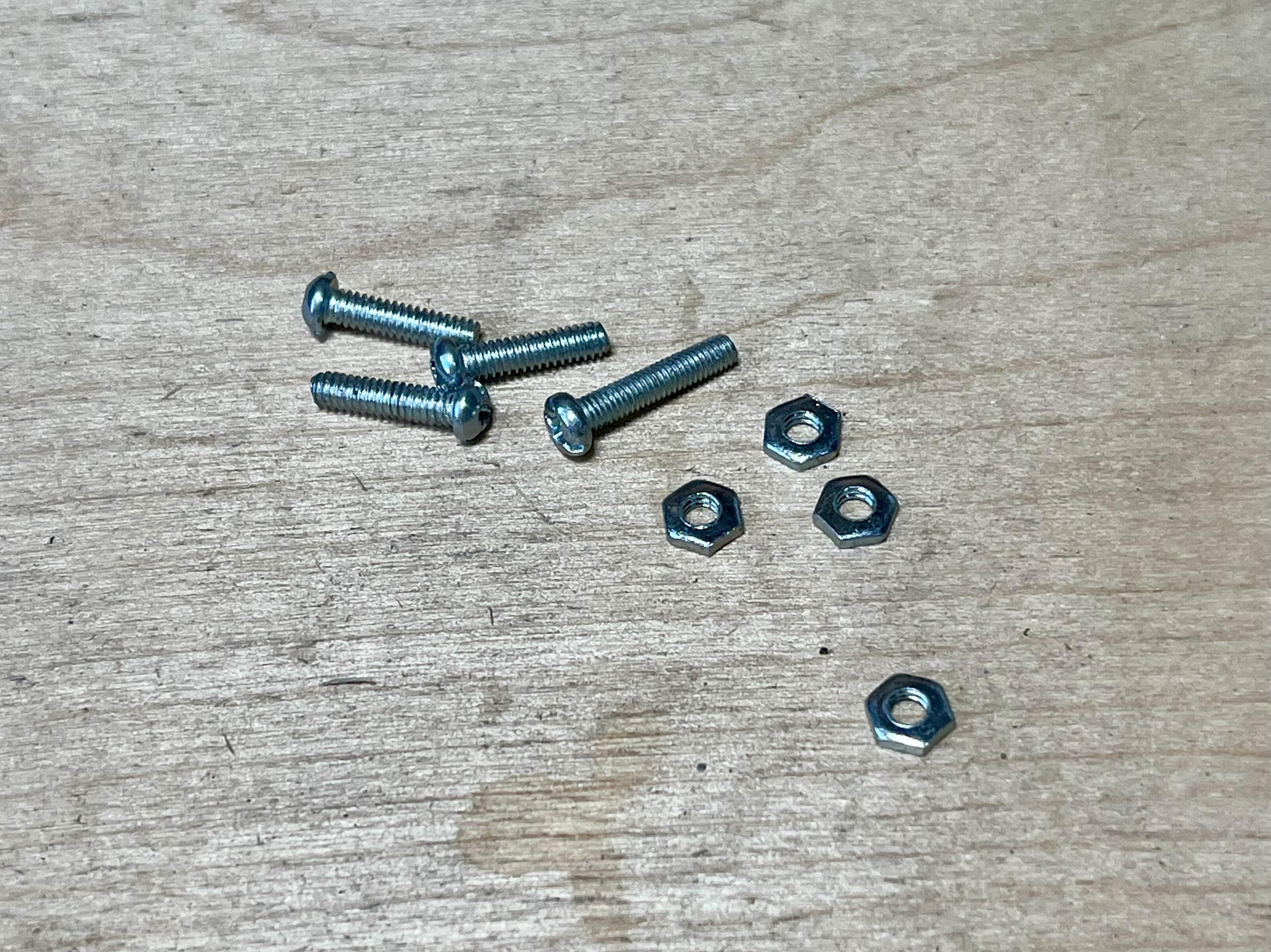
- Use some small screw and nuts to secure the Arduino to the ply wood
- Do the same with the development board. You'll need to drill your own mounting holes into the prototype board
- Lastly, use the jumper wires to connect the Arduino to the development board. I've included a wiring diagram to show you how to connect these together
That's it - you are now ready to start programming your ATtiny
Installing Arduino IDE
If you are new to all of this then you'll need to download the Arduino software. If can skip this step if you have already done it.
STEPS:
- First download a copy of Arduino IDE from the following link and install on your computer
- https://www.arduino.cc/en/software
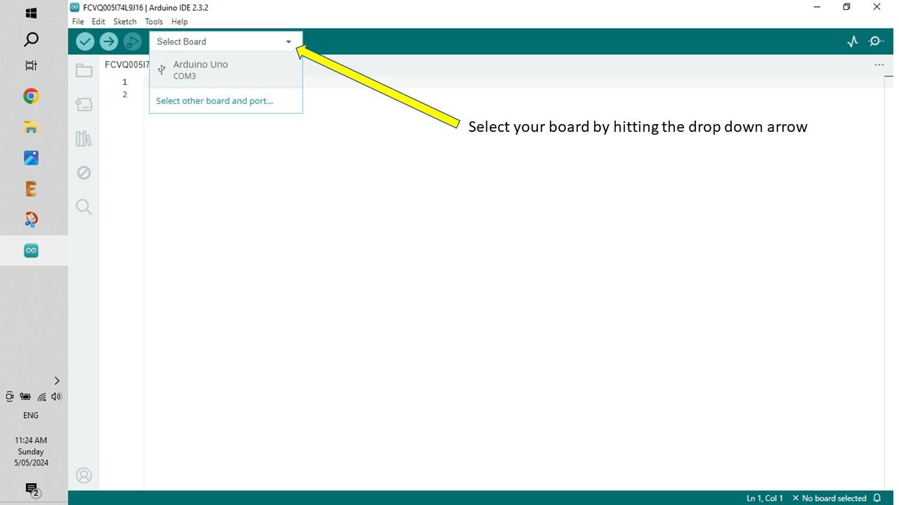
- Open it up and connect your Arduino (I'm using a Arduino Uno) to your computer via a USB cable
- Once connected, go to 'select board' and click on the Arduino Uno connection
Turning the Arduino Into a Programmer
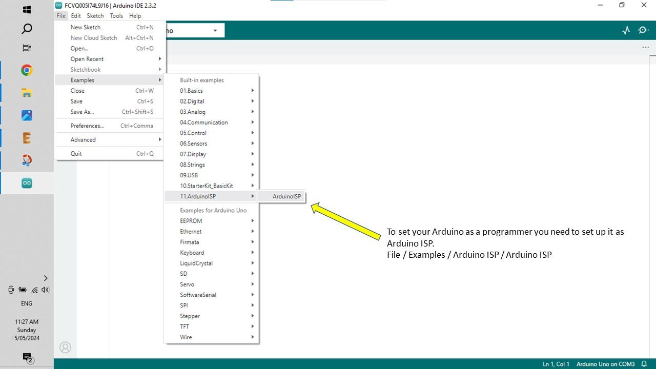
To program the ATtiny you now need to set the Arduino as a programmer. The Arduino ISP sketch turns your Arduino into an in-circuit programmer to re-program the ATtiny chip. This is really is to do so just follow the steps below.
STEPS:
- To upload Arduino ISP sketch to your Arduino, follow this path in Arduino IDE - Files / Examples / ArduinoISP (image 1)
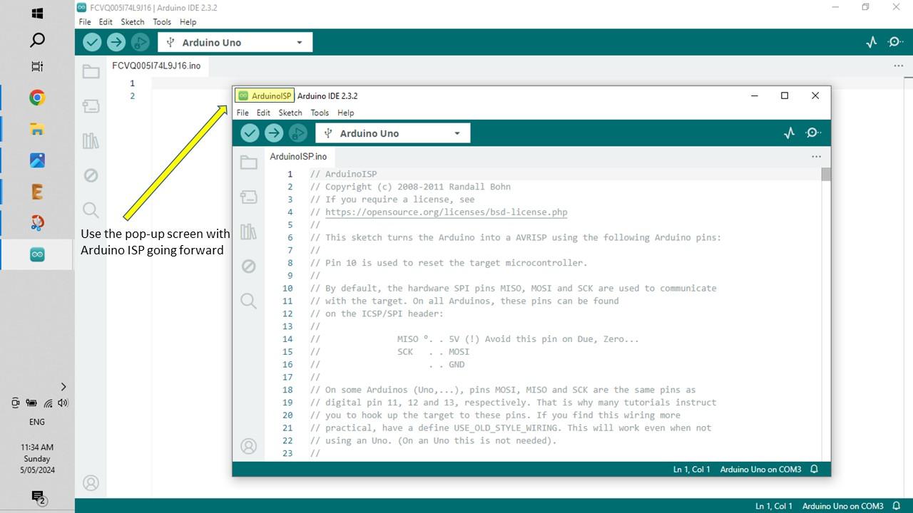
- Once you do this, another screen will pop up. You'll notice at the top left hand corner it is named Arduino ISP. (image 2)
- Now run this sketch and upload it to your Arduino
- You have now turned your Arduino into a programmer, ready to program your ATtiny!
- Now it is time to set up the ATtiny by installing its core files
Installing the ATtiny Core Files
The ATtiny core files allow your Arduino to find the ATtiny and program it.
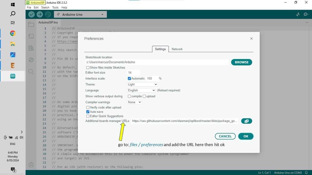
- To install these files, open: files / preferences. (image 1)
- Copy and past the following URL where it says 'Additional Boards Manager URL's “https://raw.githubusercontent.com/sleemanj/optiboot/master/dists/package_gogo_diy_attiny_index.json” (image 2)
- Hit 'OK' This will install the core files.
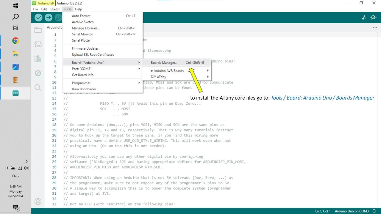
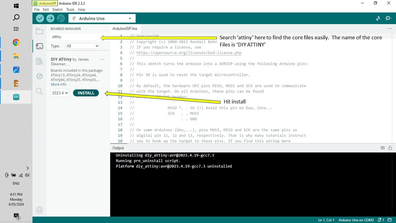
- To install the core files do the following - open: Tools / Board / Boards Manager
- Next, type in 'ATtiny' into the search bar at the top left. The core files you just added named 'DIY ATtiny' will come up. (image 3)
- Hit 'Install' to load them
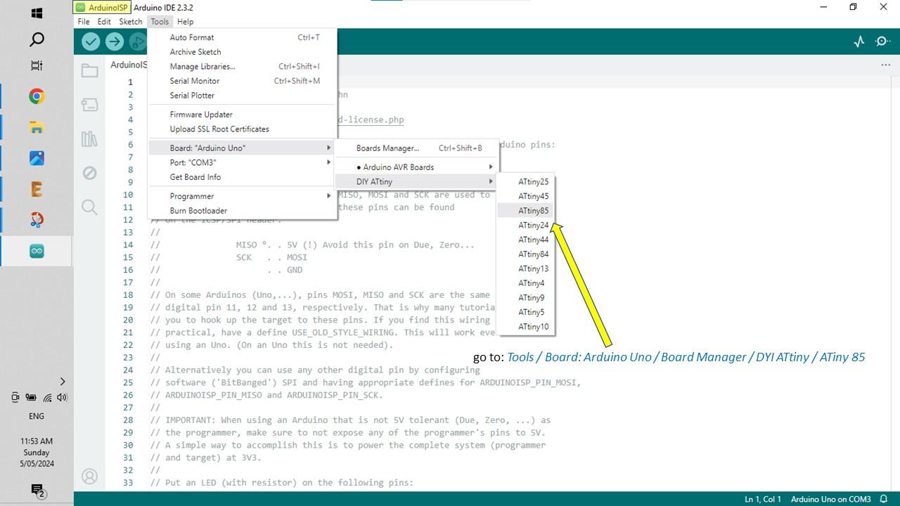
- Now if you go back into Tools / Board you will see DIY ATtiny which has a list of all the ATtiny's available
Burning the Bootloader to the ATtiny
the bootloader is a piece of firmware in your microcontroller that allows you to instal new firmware via serial communication. In order to start programming ATtiny, we must burn the Bootloader to it.
STEPS:
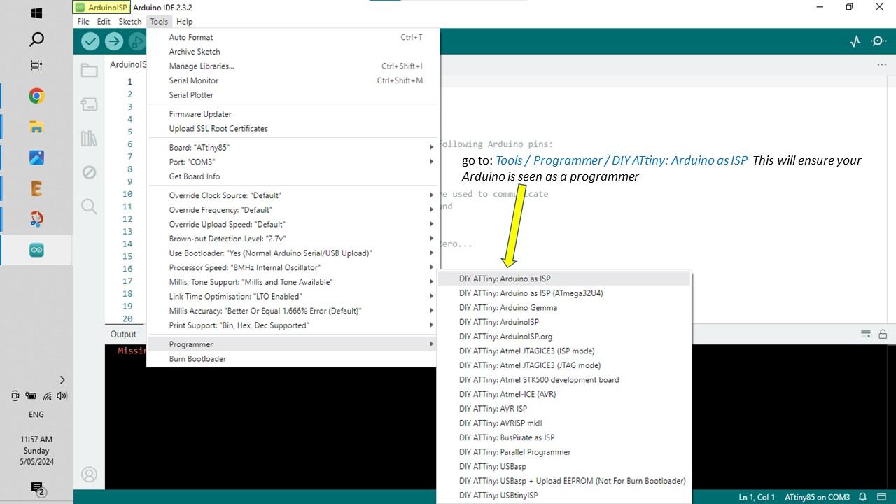
- First, you need to make sure that the Arduino is set up as a programmer. Go to Tools / Programmer / Arduino as ISP
- Now you have to set-up the ATtiny in preparation for the Bootloader.
- Go to the dropdown, select other board and port and select ATiny85
- Now go to Tools / Programmer / DIY ATtiny: Arduino as ISP and hit 'DIY ATiny: Arduino as ISP' (image 2)
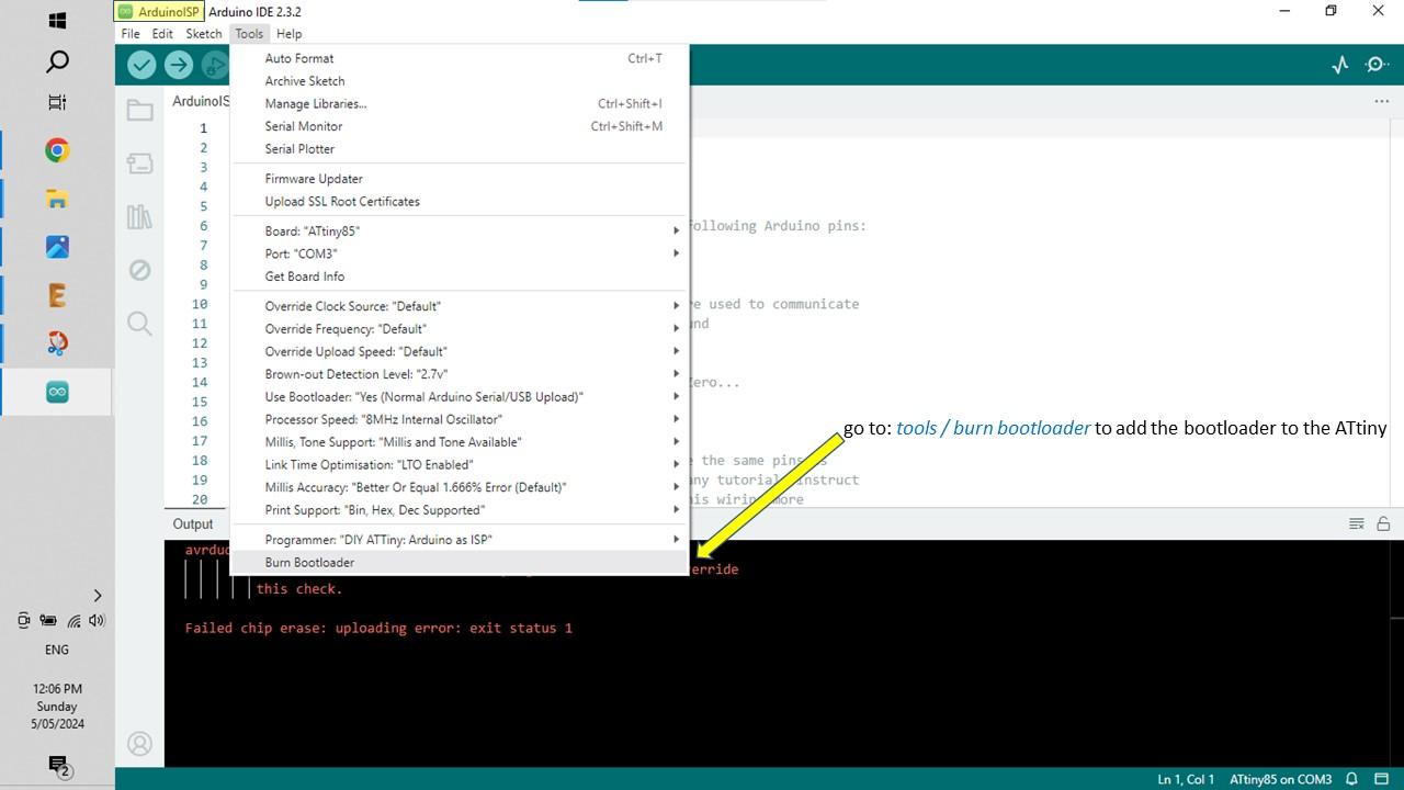
- Now you can install the bootloader by simply going to: Tools / Burn Bootloader. If successful it will come up with a message saying 'done burning bootloader' (image 3)
- After burning the Bootloader, the ATtiny is now ready to be programmed. The best and most common way to ensure everything is working is to load up the blink sketch which we'll do in the next step.
Loading the Blink Sketch
All the blink sketch does is flash an LED on and off. However, if it is successful then you will know that you have followed all of the steps successfully.
STEPS:
- In Arduino IDE, go to File / New Sketch
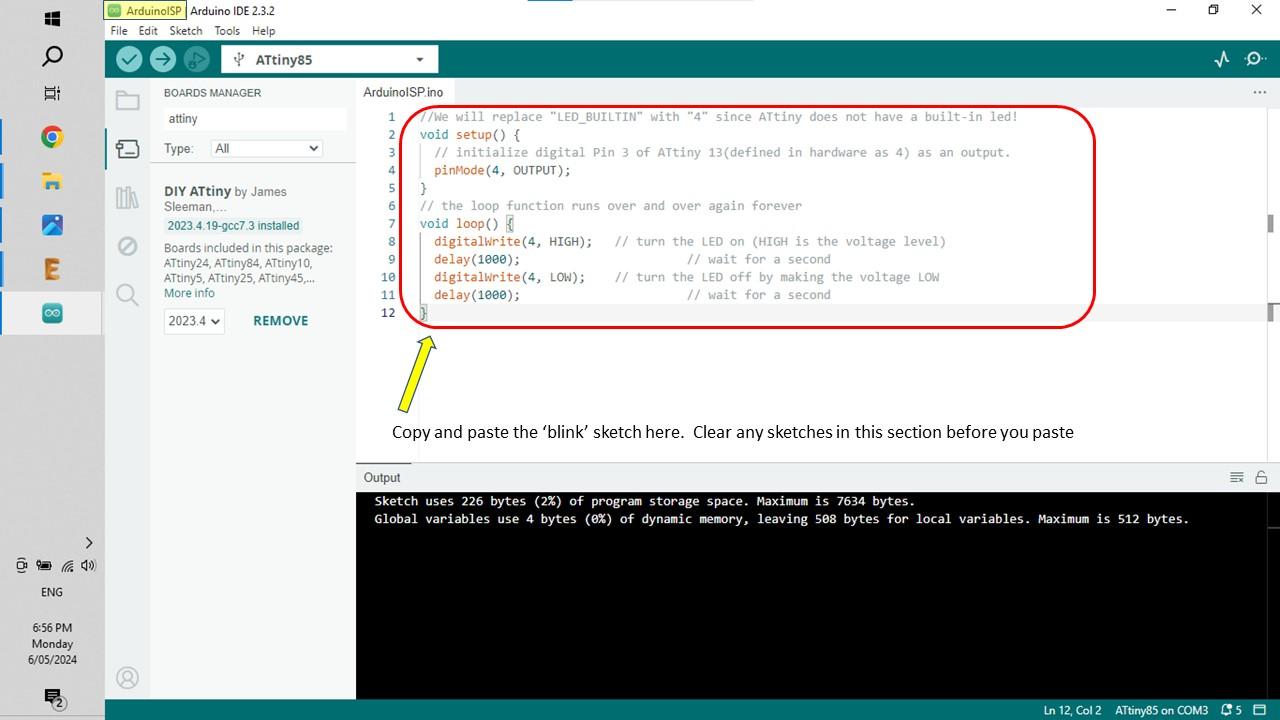
- Copy the code in the supporting file below and paste it into the sketch screen (image 1)
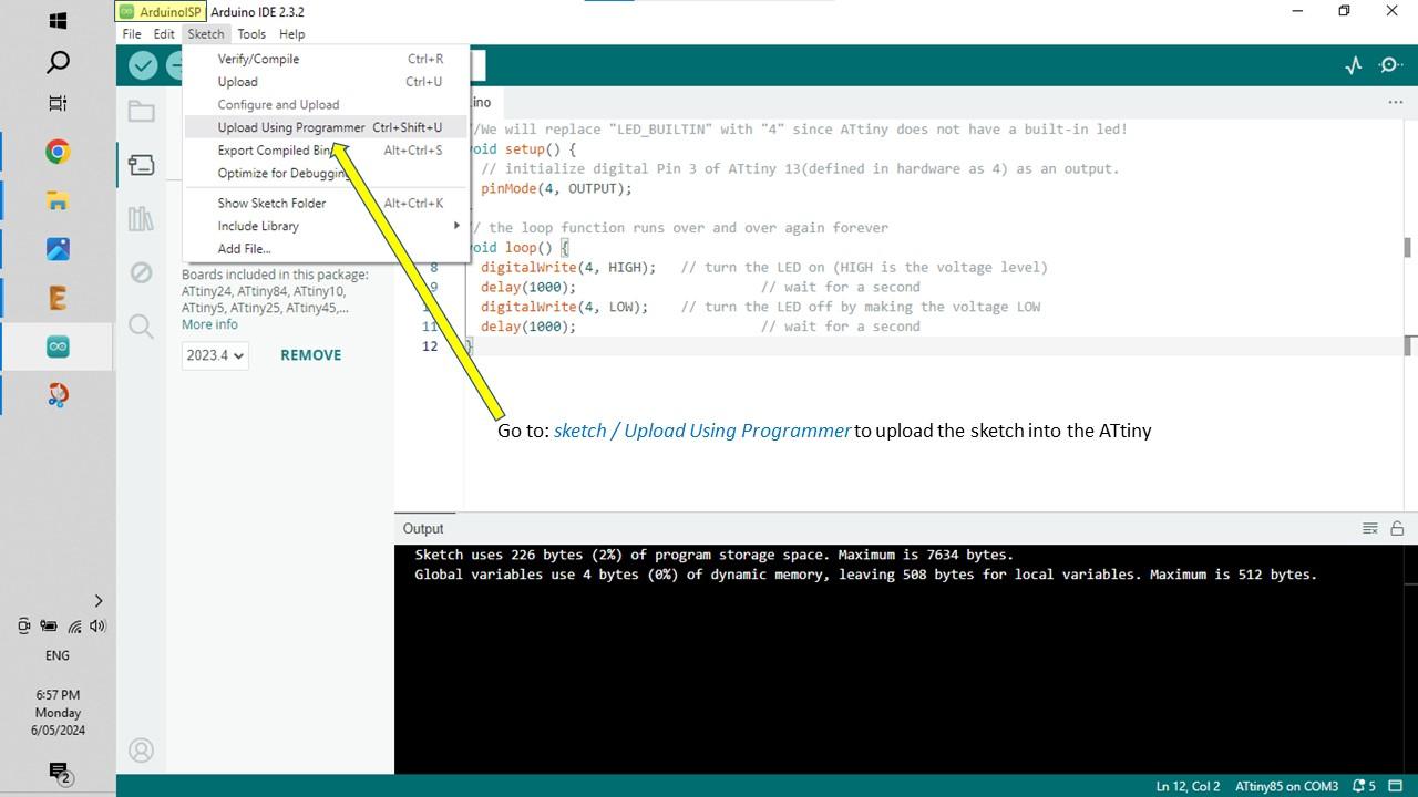
- To upload the program you need to go open the following: Sketch / Upload Using Programmer (image 2)
- If everything works as it should you will see the LED blinking on and off.
Congrats - you have just programmed your first ATtiny. Now go on-line and look up projects that you can do for the ATtiny. There are a heap of fun ideas and projects to build using this great little chip.