How to Program Any Type of AVR Microcontroller With Arduino Ide || Hex Shield || Attiny85 || Atmega8 || Atmega32
by vishalsoniindia in Circuits > Arduino
2300 Views, 7 Favorites, 0 Comments
How to Program Any Type of AVR Microcontroller With Arduino Ide || Hex Shield || Attiny85 || Atmega8 || Atmega32
Please subscribe to my YouTube channel.........
In this article we will learn how to program any type of avr microcontroller using arduino IDE via arduino.
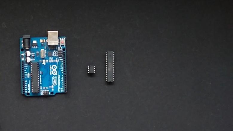
I am explaining a concept to program any avr microcontroller with help of Attiny85 example.
By the way, subscribe to my YouTube channel for more projects like this. I also update my upcoming projects on Instagram.
buy me a coffee! ☕: Donate
Arduino As ISP
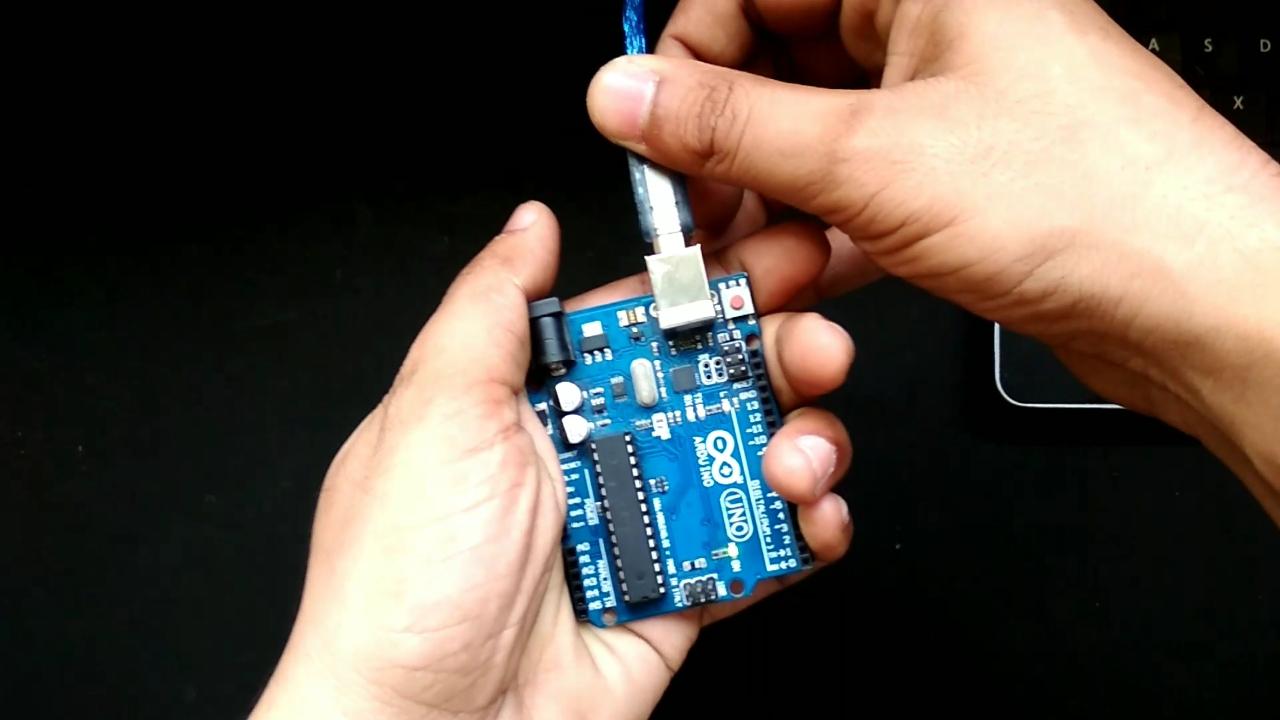
- Take your arduino
- Connect with your pc.
- Open arduino IDE.
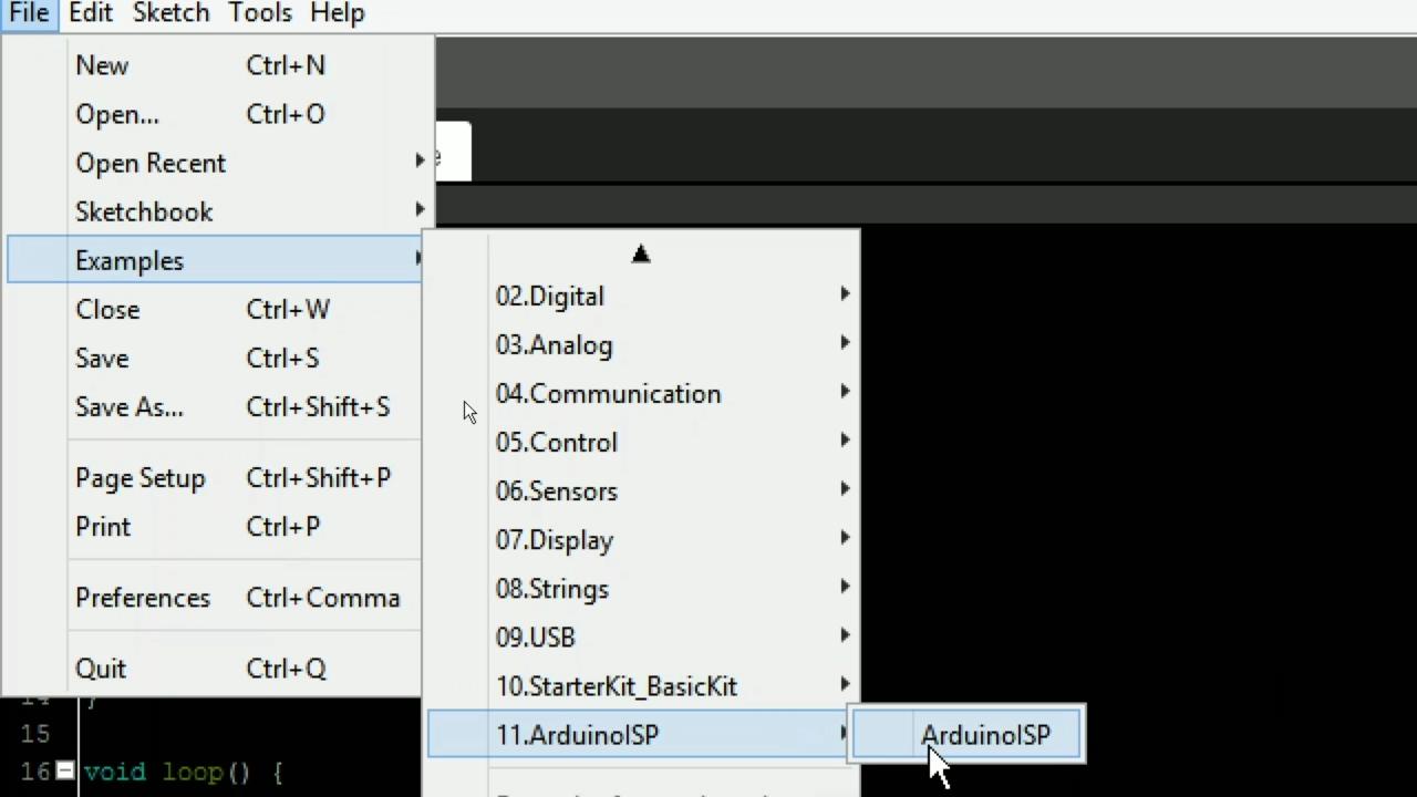
- Go in file >> example >> ArduinoISP
- Open ArduinoISP program.
- Select correct board and port in tools.
- Now upload the code.
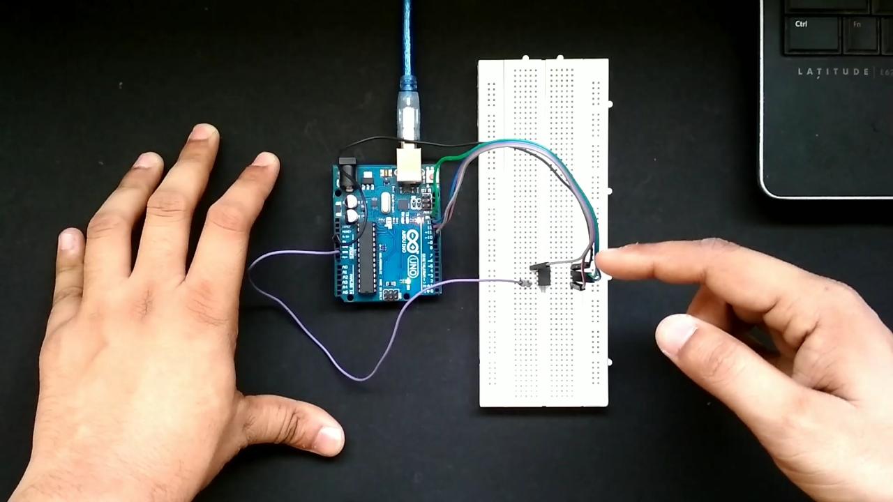
Program AVR Via Arduino Circuit
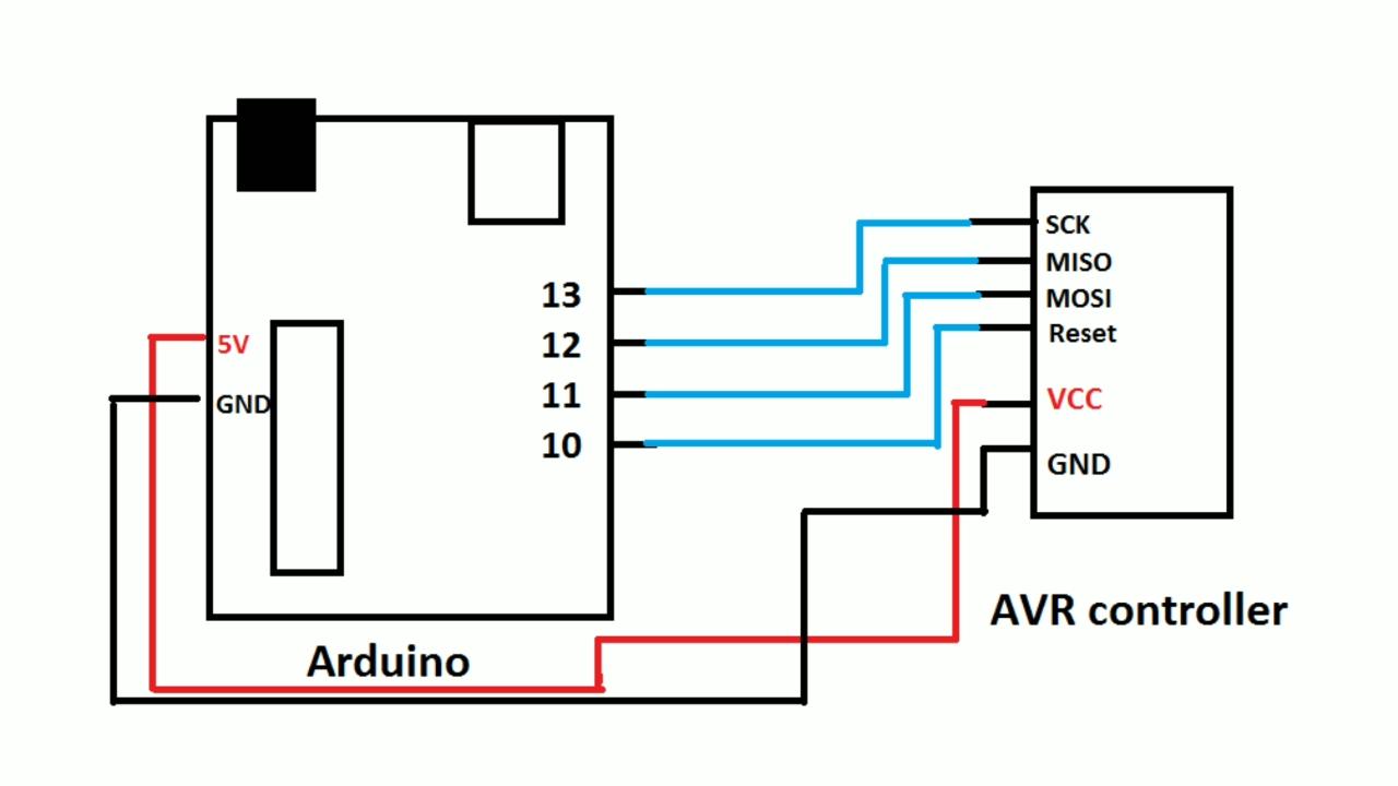
- In the circuit the SCK,MISO,MOSI,RESET pins of AVR are respectively connected with 13,12,11,10 pin of arduino
Arduino's 13 pin -----------------> SCK of AVR
Arduino's 12 pin -----------------> MISO of AVR
Arduino's 11 pin -----------------> MOSI of AVR
Arduino's 10 pin -----------------> RESET of AVR
Arduino's +5v pin -----------------> VCC of AVR
Arduino's GND pin -----------------> GND of AVR
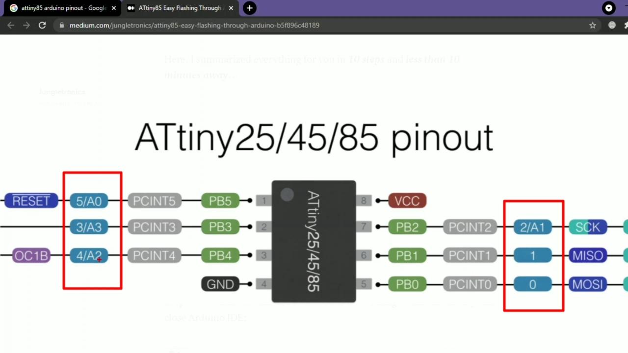
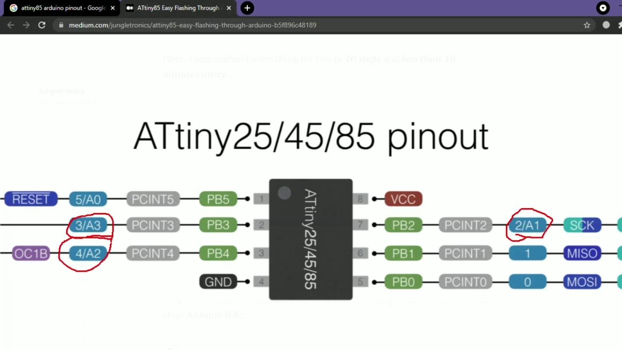
ICSP Pinout of AVR

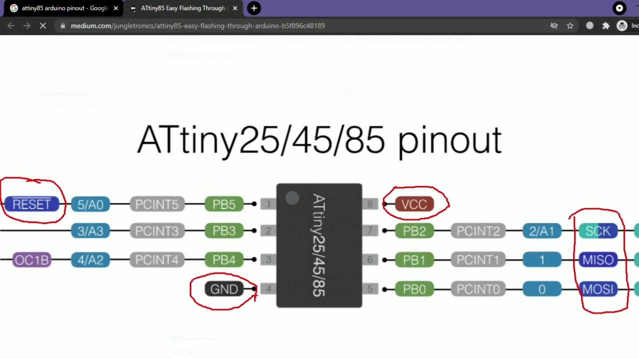
- Search "Attiny85 arduino pinout" in google.
- find the image same as given.
- find the ICSP pins, SCK,MISO,MOSI,RESET and VCC,GND
- Connect ICSP pins as shown in circuit.
Find AVR Board Link for Arduino IDE

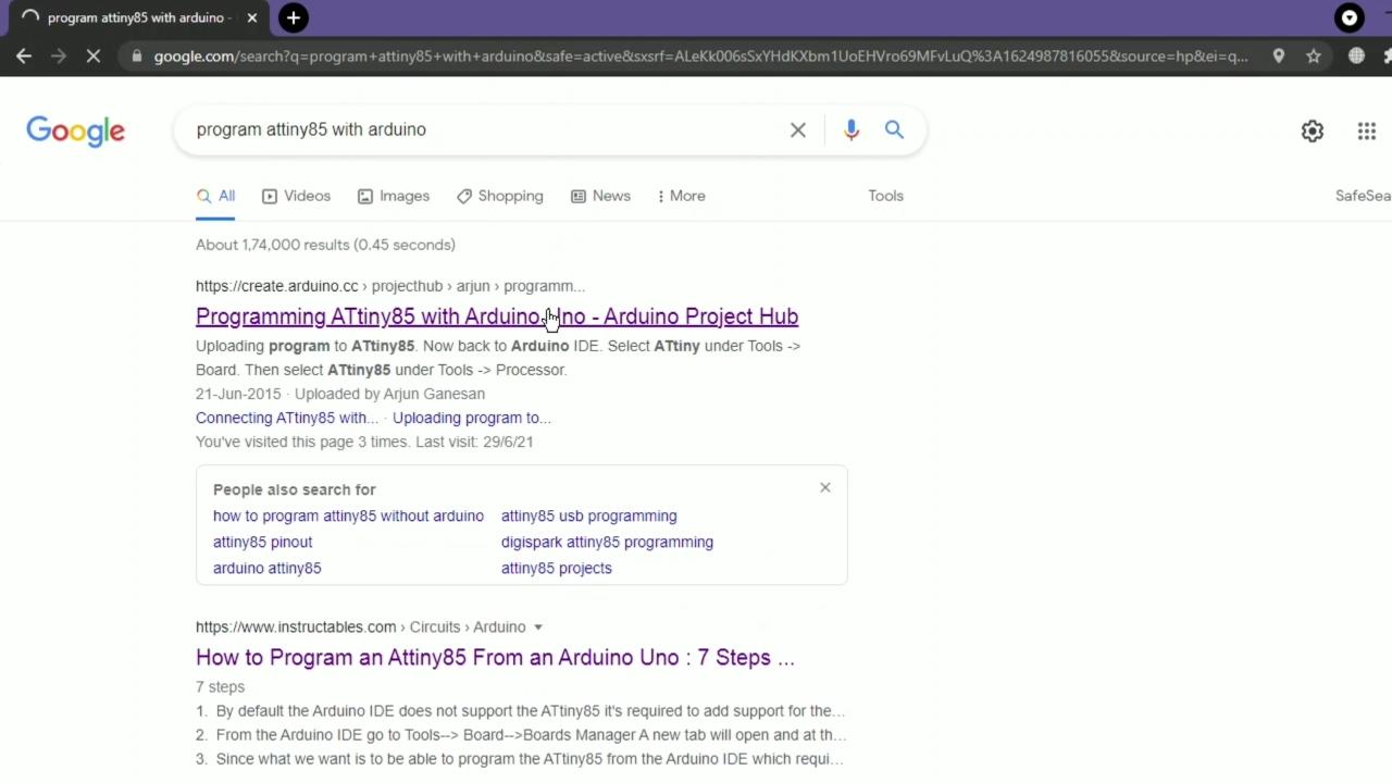
- Search "Program Attiny85 with arduino".
- Find the Board link in google results.
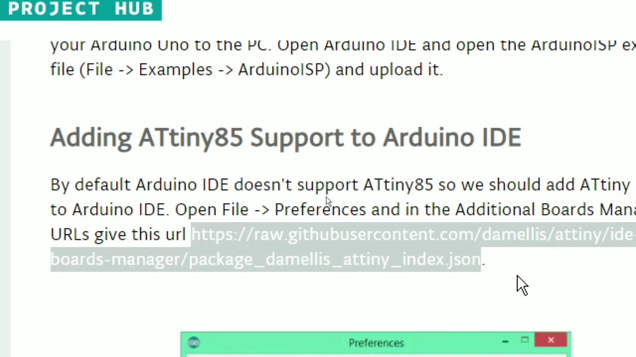
- Copy the the board link for attiny85 the link given below.
https://raw.githubusercontent.com/damellis/attiny/ide-1.6.x-boards-manager/package_damellis_attiny_index.json
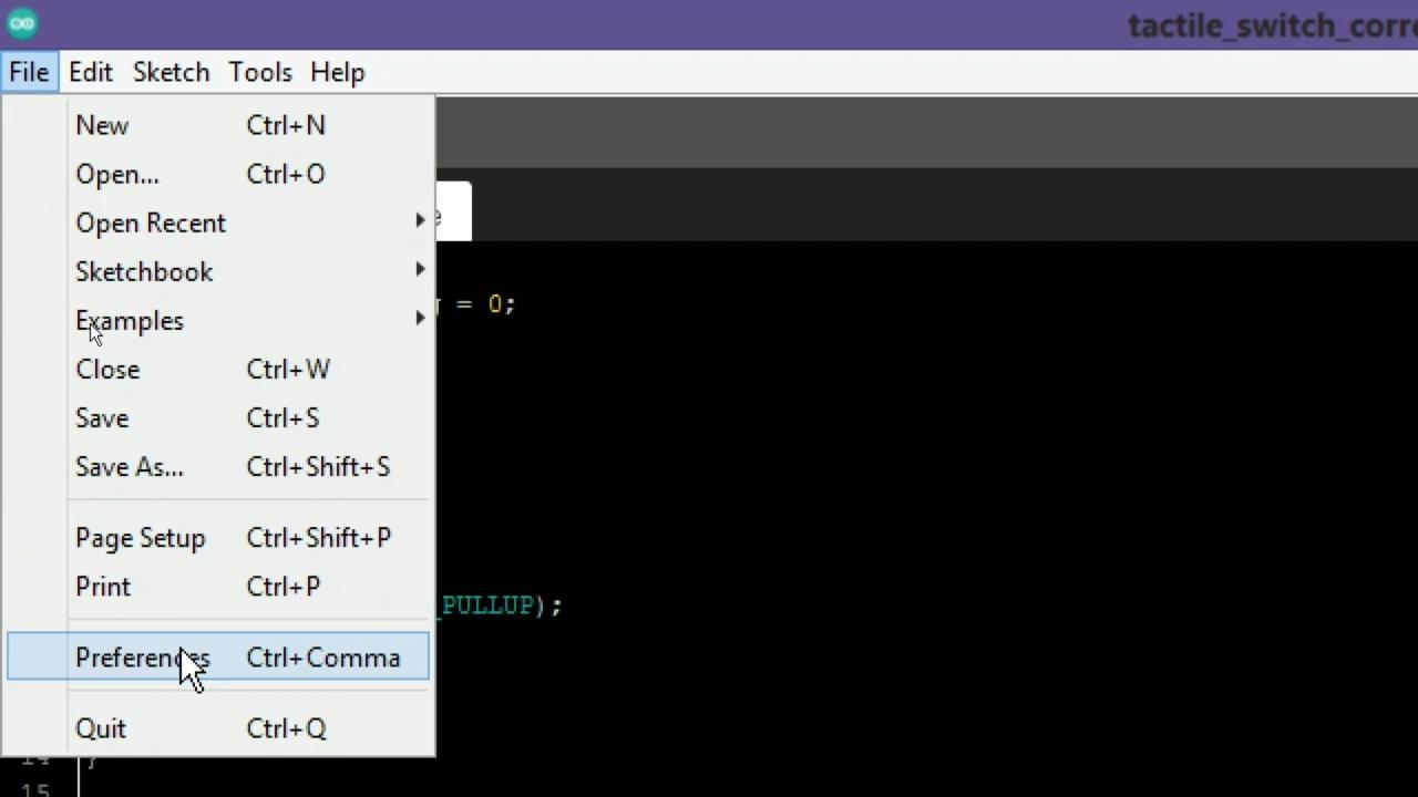
- Go to the arduino IDE.
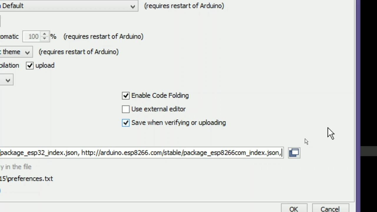
- Click on File -> Preferences
- Paste the link in Boards Manager URLs. if there is other links, then paste link after comma ",".
Install the AVR Board for Arduino IDE
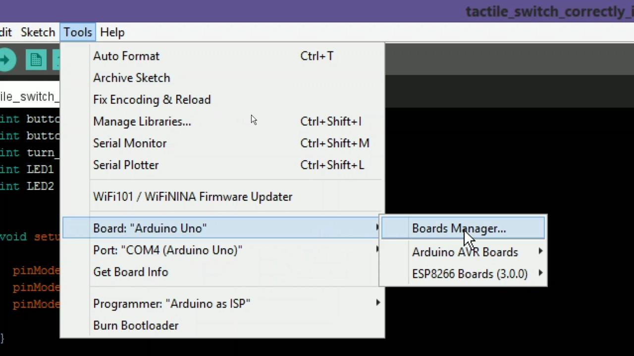
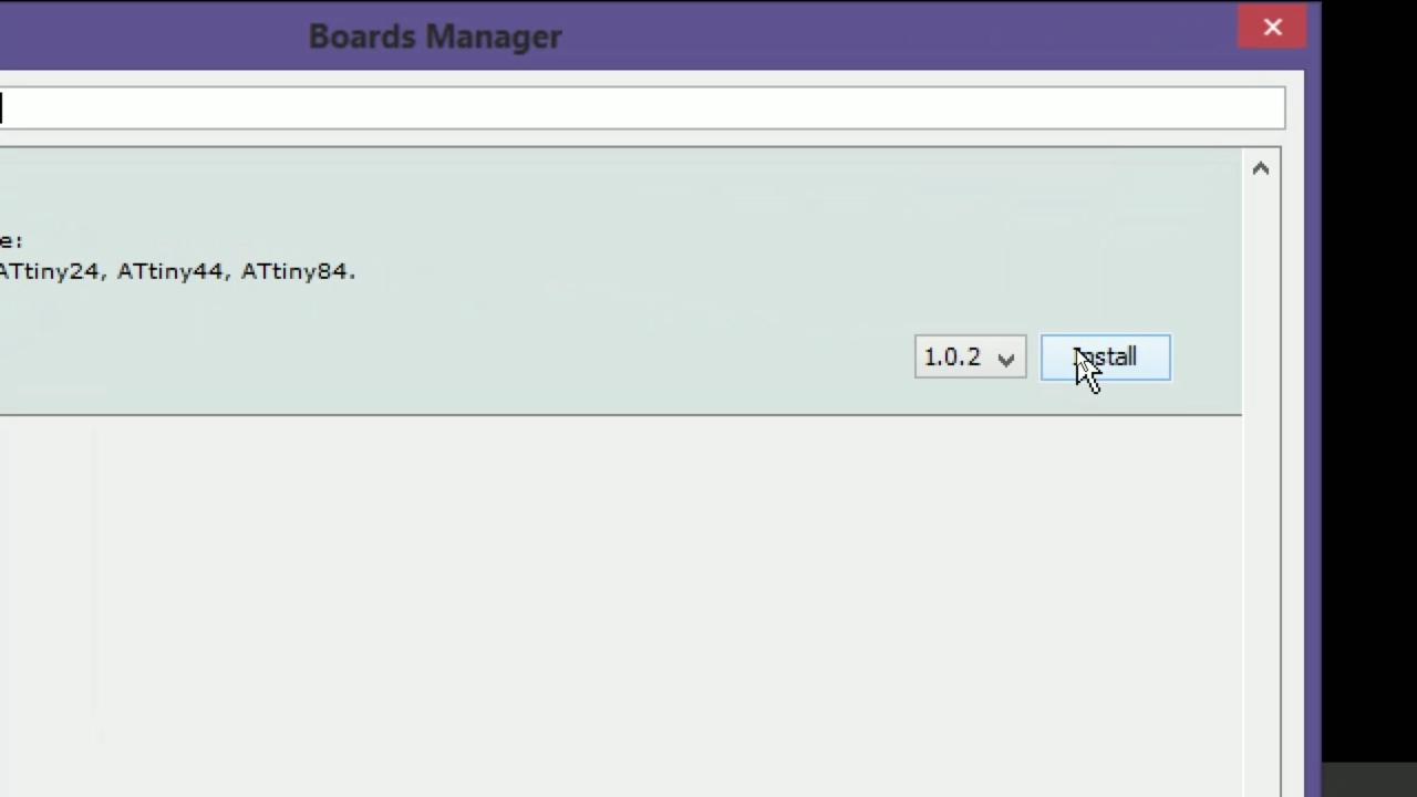
- Go the Board manager via "Tools >> Board >> Board manager"
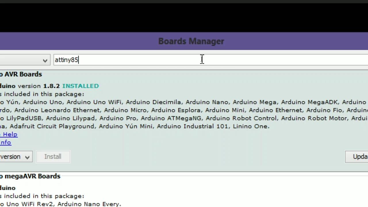
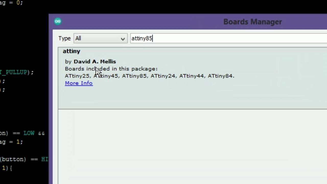
- Here search "Attiny85".
- You will get a Library install it.
Upload Bootloader in AVR and Upload Program in AVR
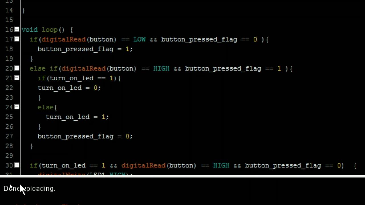
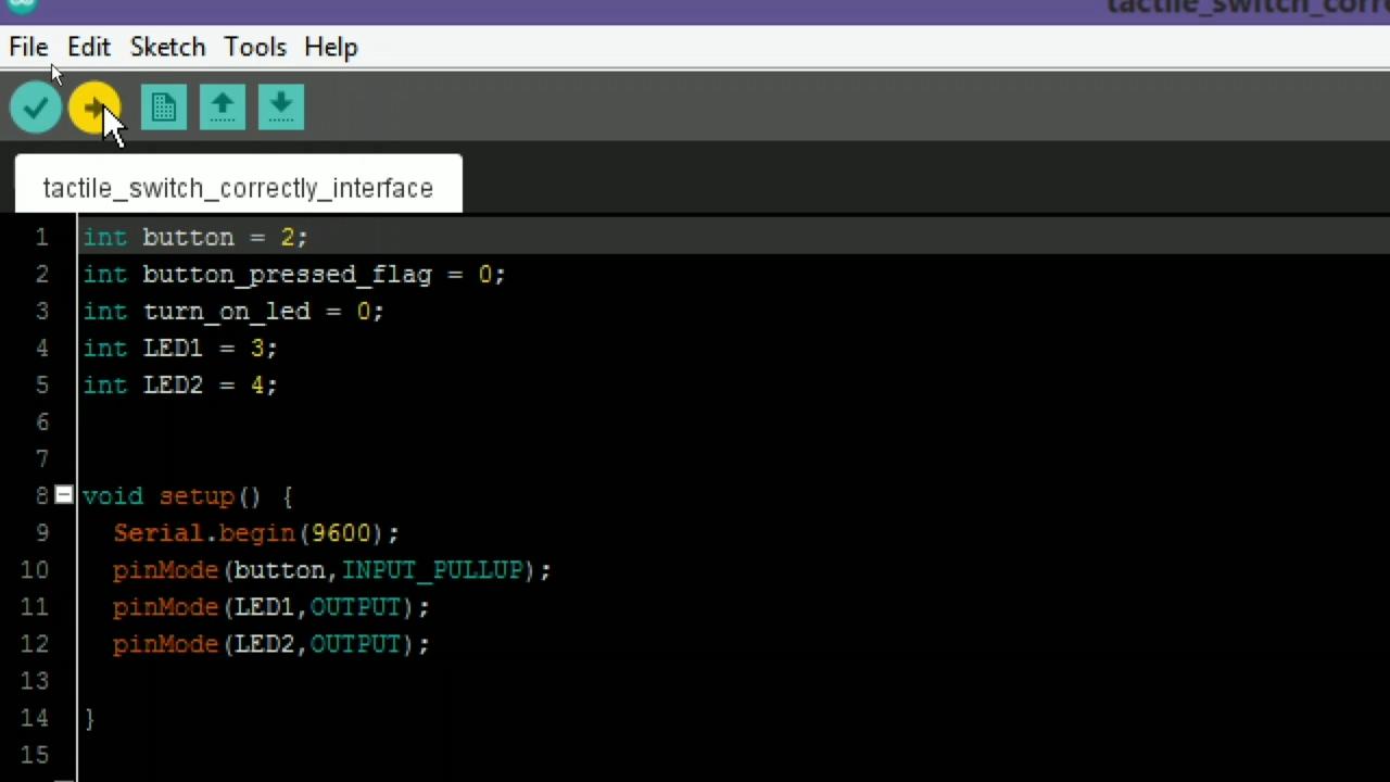
- Open the code which you want to upload in AVR or you an download the code from github page given below.
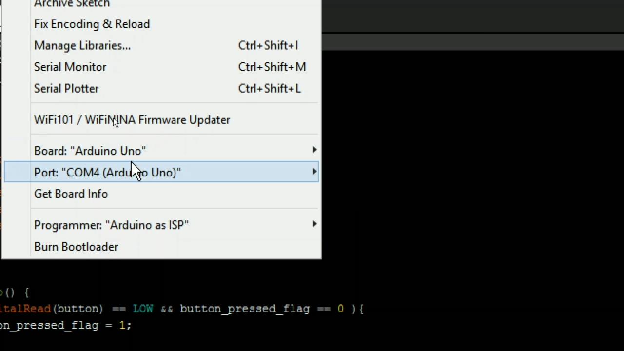
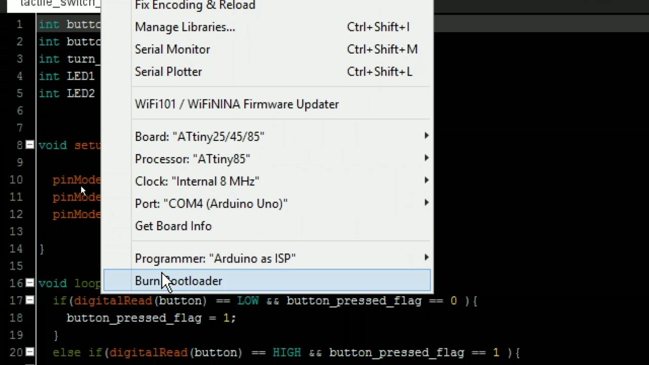
- Select Attiny category in board.
- Select processor as attiny85.
- Select clock as internal 8Mhz.
- Select programmer "Arduino as isp".
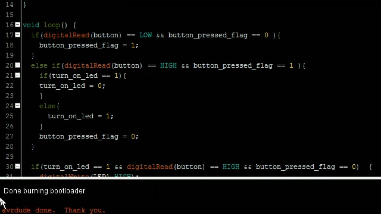
- Click on upload bootloader.
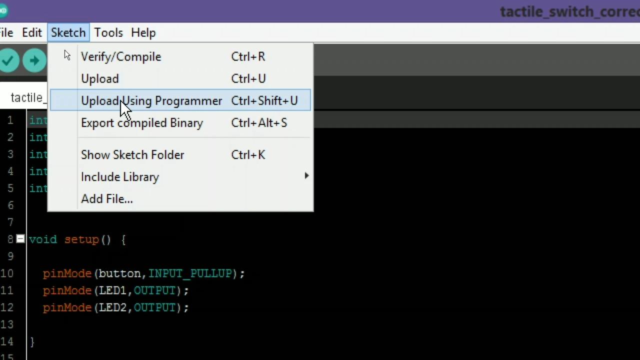
- After bootloader uploaded go to the sketch.
- Go to the sketch >> Upload using programmer.
- The code will be uploaded successfully.
github link : - https://github.com/vishalsoniindia/Program_AVR_fro...
Connect Circuit As Program
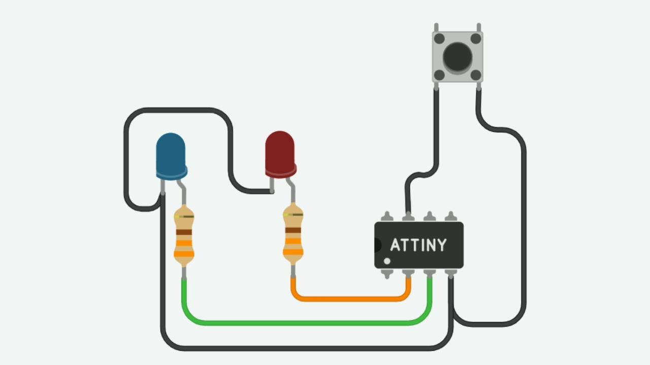
if you uploaded my code then you can connect circuit as shown.
- Push button is connected to 2nd pin of AVR
- Two leds is connected at 3rd and 4th pin of AVR.
Done
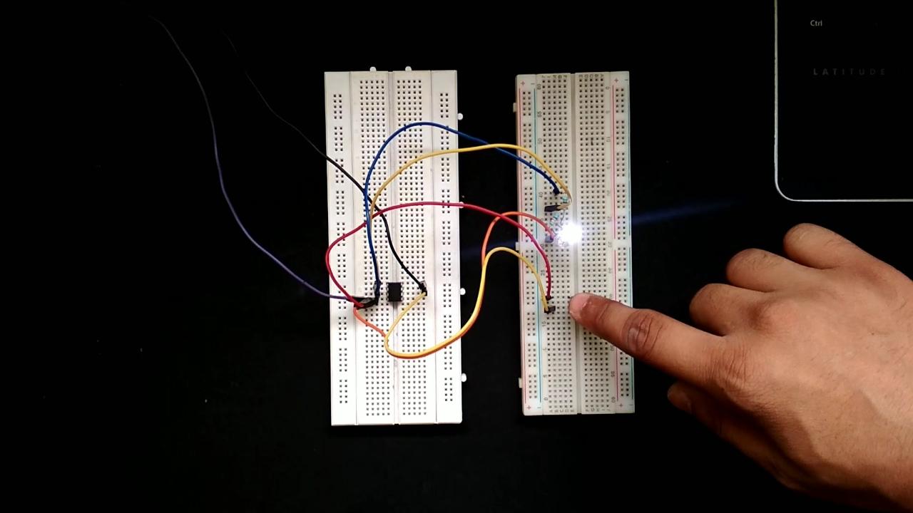
- Now you can see the Push button turn on led Alternatively.
Hex Shield
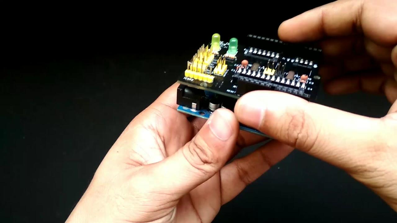
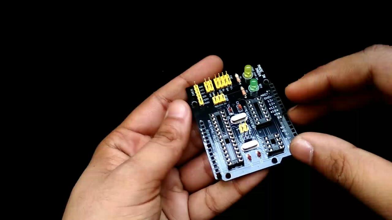
- If you don't want to mess with wires then you can use the hex shield.
- The Gerber file and schematic is given below on github link .
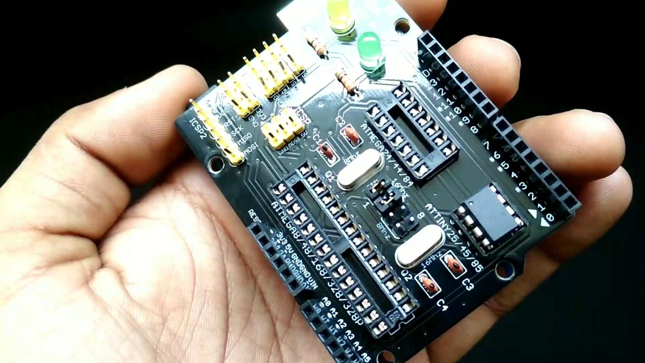
- The shield many type of controller all are written on the shield.
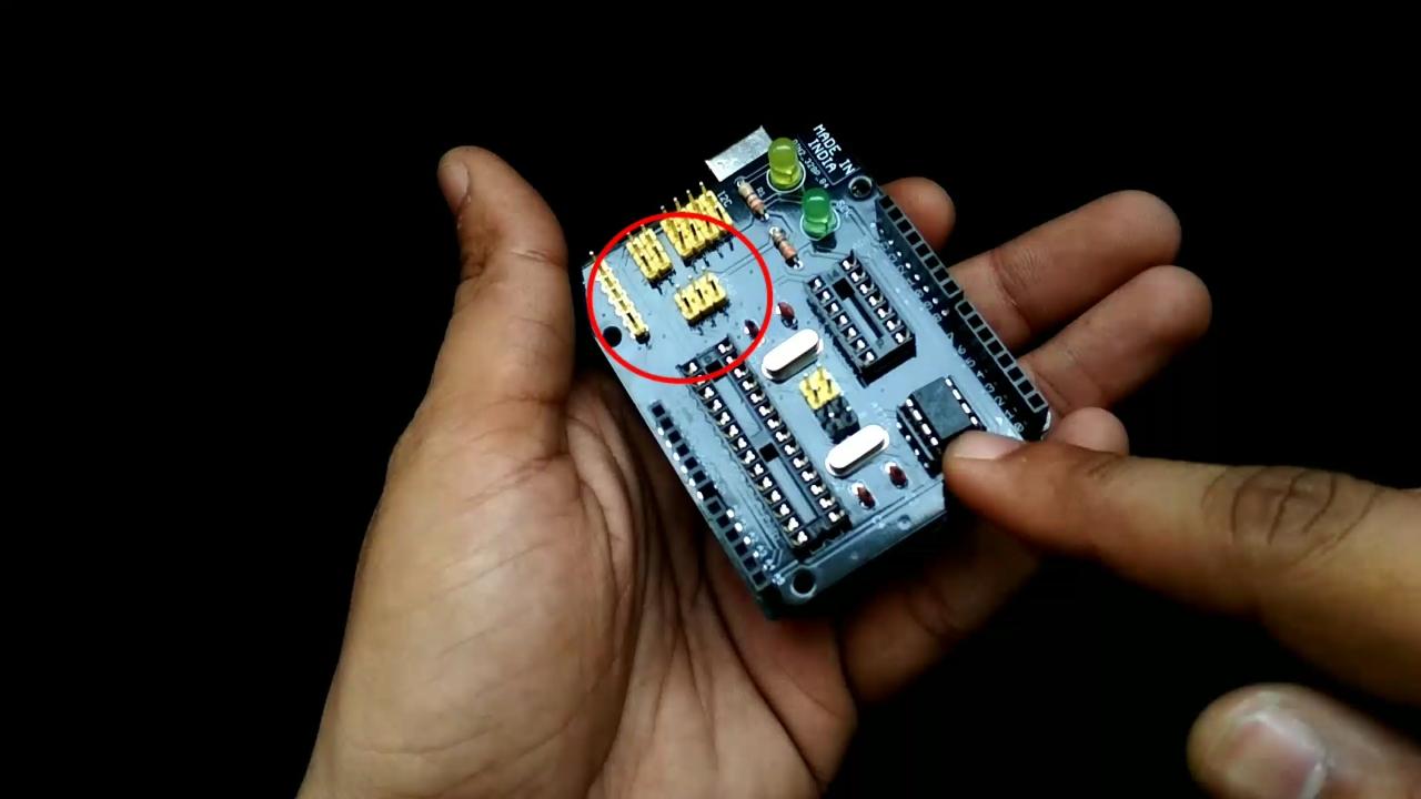
- if any AVR is out of this list then you can program it via ICSP pins on shield.
- the shield has crystal selection jumper for 8Mhz and 16Mhz.
Github :- https://github.com/vishalsoniindia/Program_AVR_fro...
Order PCB
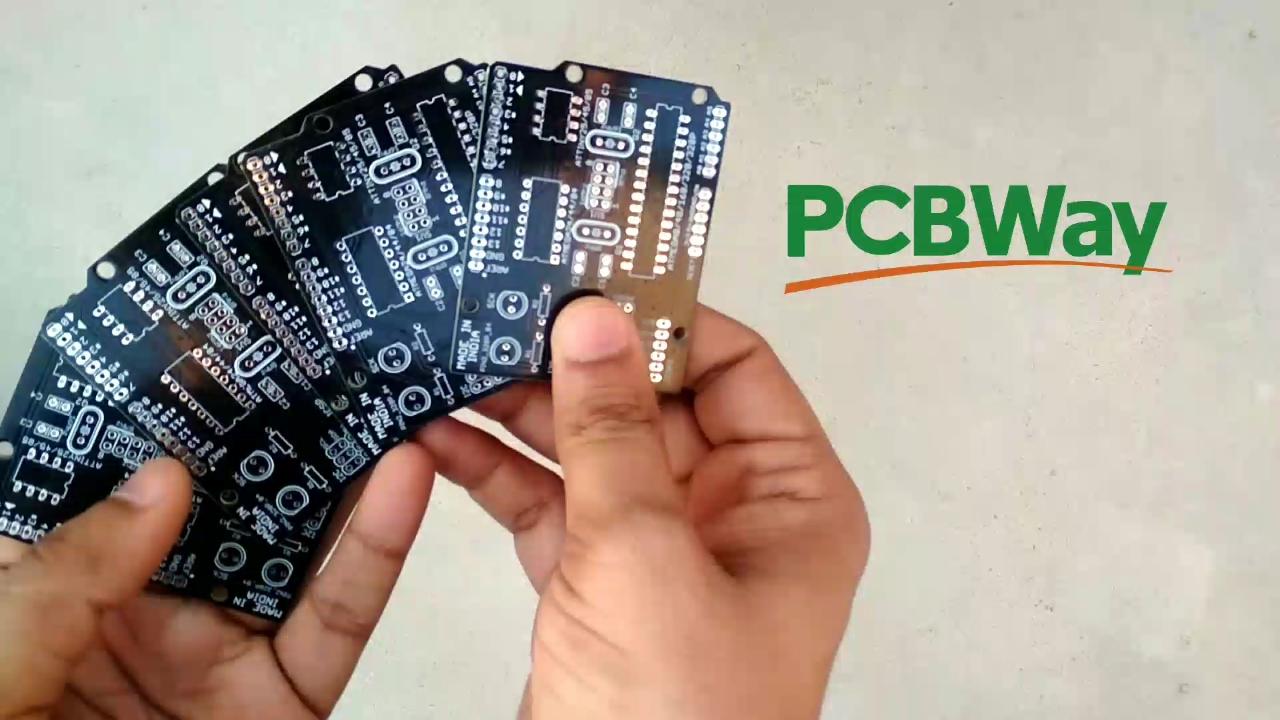
- This PCB is sent by PCBway you can order high quality PCB from PCBway.
- Link to order PCB :- https://www.pcbway.com/
buy me a coffee! ☕: Donate