How to Multiplex Multi Digit LED Displays With a Shift Register and Transistors. a Short Guide.
by adrian-smith31 in Circuits > LEDs
639 Views, 2 Favorites, 0 Comments
How to Multiplex Multi Digit LED Displays With a Shift Register and Transistors. a Short Guide.

In this example I will show you how to multiplex a 7 segment LED display from a microcontroller such as an Arduino without placing too much load on the microcontroller pins as I have seen in some other examples - not necessarily on this site I might add! Quite a few tutorials I’ve seen are not really good practice for electronics design – some even don’t use current limiting resistors!
Supplies
Common anode 7 segment LED displays 0.3-0.8"
TPIC6B595 shift register
2N3906 PNP transistor (or equivalent)
The Most Common Method of Multiplexing
So to start off I'm going to talk about what is the most common go to method of multiplexing LED displays which is to directly connect the segments (via current limiting resistors) and digit commons to the microcontroller pins. This method uses the least amount of components but the disadvantage is you need 8 pins for the segments if using the decimal point and one for each digit. Another disadvantage is you are limited to the amount of current you can put through the displays and in turn brightness of the display.
You see a multiplexed display can be run directly from a micro without a shift register as long as the current limit of the microcontroller pins is observed, in the ATMega328’s case is 20mA typical, 40 absolute maximum per pin. But you have to watch out for the total current allowed per port and for the whole chip to avoid excessive power dissipation leading to bonding wire failure or the magic smoke. Some ports can supply up to 200mA but the whole chip is also limited to 200mA. For good design practice it's best to go nowhere near the absolute maximum ratings of a semiconductor device. I personally don't like to go over 50%, 75% absolute maximum. In this configuration the segments are driven from one set of pins and the digits another. This method uses a lot of pins on the microcontroller and in most cases can overload the pins used for the digits. Hence this is only suitable for 2-4 digit displays and limiting the average current per segment to 5mA or less.
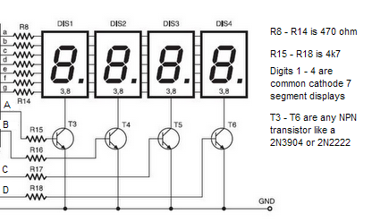
High efficiency LED displays are required for this method otherwise you will have a dim display. So, to solve the problem of overloading the pins on the microcontroller, transistors are a must for the digit selection as, with all digits on showing 8. 40mA could flow through one pin if an average of 5mA were to be used. This is right on the absolute maximum for the microcontroller. A PNP transistor (common anode) or NPN transistor (common cathode) is recommended. This way you can increase the segment current to a suggested 12mA and connect the segments to a 150mA+ capable port to stay within acceptable limits of an ATMEGA328P microcontroller. For others you would need to check the datasheet to see what the maximum ratings are for the I/O ports. An example circuit is shown below.
One thing that you have to remember with multiplexing a single digit is only on for x number of total digits e.g. a 4 digit display is only on for 1/4 of the time so you would need to increase the current by 4 times so the segment current needs to be 20mA to get the same brightness as a non multiplexed display. That times 8 segments is 160mA – OK for some of the ports on the ATMega328P but the chip has an absolute maximum of 200mA for the whole chip. This limits the amount of current and the number of digits on your display. You could use a driver chip like the MAX7219 instead (which I really would recommend) but this isn’t the subject of this article.
A video is attached to this step as an example of multiplexing in action.
Downloads
Multiplexing With Shift Registers Instead

So, to avoid overloading and following good practice use a shift register to drive the segments instead. The common 74HC595 is a likely go to chip for hobbyists but it has even less sink / source current than the ATMEGA series of chips. A transistor array would be required between the HC595 and the LED displays but this increases cost and circuit complexity. Enter the TPIC6B595; a power logic shift register that can sink up to 150mA absolute maximum per pin and a total limit of 500mA for the whole chip.
Note that unlike the 74HC595 the TPIC6B595 has a couple of drawbacks the first of which is it only accepts 5V logic level inputs so to use with a 3.3V microcontroller you need a logic level shifter. The second is it can only sink current due to it’s open drain outputs so it can only be used with common anode LED displays. If you use this chip you can safely increase the current through the displays to increase the brightness or use for larger displays – but watch out the total current if all segments were on does not exceed 500mA. In all cases, the datasheet for the chip should be read!
An example circuit is shown above that uses LED displays with a forward voltage of 2.2V. For displays that use less forward voltage you need to increase the current limiting resistor value accordingly. 68ohms is a good example in this 5 digit display if using 1.8V red displays.
Example code sample where the digits are cycled through using a switch case and in each case the digit patterns are shifted out after the latch is set low then the latch is set high then the digit pin is switched on. After each cycle through the digit pins are switched off. Note that in this example I'm using PNP transistors so a logic high turns it off and vice versa. In this example the previous digit is not switched off when the next one is turned on; for some bizzare reason if I did this the display would be dim on the 2nd and 4th digit. Depending on the microcontroller you use it may be best to turn off the previous digit when the next one is turned on rather than at the end of the display scan. This is really how it should be done. There's also a small delay between digits which is not ideal but this is prototype code.
// turn all digits off by setting digit pin high on each loop through.
    PORTD |= (1<<PORTD2);
    PORTD |= (1<<PORTD3);
    PORTD |= (1<<PORTD4);
    PORTD |= (1<<PORTD5);
    PORTD |= (1<<PORTD6);

   if (grams <-9 || grams >10010) // show error if minus figure or scale is overloaded


    {
     switch (digit)
     {
      case 0:
        SPI.beginTransaction(SPISettings(8000000, LSBFIRST, SPI_MODE0));
        PORTB &= ~(1<<PORTB2); // set latch LOW
        SPI.transfer(B11110010); //E
        PORTB |= (1<<PORTB2); // set latch HIGH
        SPI.endTransaction();
        PORTD &= ~(1<<PORTD2); // set digit pin 0 LOW
        delay(2);
        break;

      case 1:
        SPI.beginTransaction(SPISettings(8000000, LSBFIRST, SPI_MODE0));
        PORTB &= ~(1<<PORTB2); // set latch LOW
        SPI.transfer(B10100000); // r
        PORTB |= (1<<PORTB2); // set latch HIGH
        SPI.endTransaction();
        PORTD &= ~(1<<PORTD3);
        delay(2);
        break;

      case 2:
        SPI.beginTransaction(SPISettings(8000000, LSBFIRST, SPI_MODE0));
        PORTB &= ~(1<<PORTB2); // set latch LOW
        SPI.transfer(B10100000); //r
        PORTB |= (1<<PORTB2); // set latch HIGH
        SPI.endTransaction();
        PORTD &= ~(1<<PORTD4);
        delay(2);
        break;

      case 3:
        SPI.beginTransaction(SPISettings(8000000, LSBFIRST, SPI_MODE0));
        PORTB &= ~(1<<PORTB2); // set latch LOW
        SPI.transfer(B10111000); // o
        PORTB |= (1<<PORTB2); // set latch HIGH
        SPI.endTransaction();
        PORTD &= ~(1<<PORTD5);
        delay(2);
        break;


      case 4:
        SPI.beginTransaction(SPISettings(8000000, LSBFIRST, SPI_MODE0));
        PORTB &= ~(1<<PORTB2); // set latch LOW
        SPI.transfer(B10100000); //r
        PORTB |= (1<<PORTB2); // set latch HIGH
        SPI.endTransaction();
        PORTD &= ~(1<<PORTD6);
        delay(2);
        break;
      }

        digit++;

    if (digit == 5)
      {
        digit = 0;
      }
   }

    else // display normally
Photo of Completed Project Using This Example

You can reduce pins used on the microcontroller even further by using another shift register (a 74HC595) daisy chained to the TPIC6B595 to control the bases of the digit common transistors instead. There is an example of this method on this site.
I hope you find this useful.
If you are interested in making this HX711 weigh scale project I will release it here when finished but for now you can check out the build of my prototype on my blog. Link in my profile.