How to Make an Otto Robot Using Raspberry Pi Pico
by Shahbaz Hashmi Ansari in Circuits > Raspberry Pi
884 Views, 5 Favorites, 0 Comments
How to Make an Otto Robot Using Raspberry Pi Pico
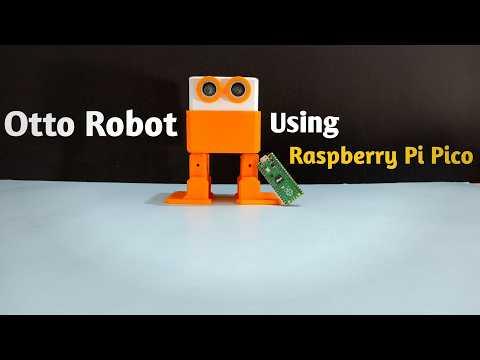
Greetings everyone, and welcome to my Instructables tutorial. Today, I'll guide you through the process of creating an Otto Robot using Raspberry Pi Pico.
Project Overview:
This project is about Otto Robot using Raspberry Pi Pico. The Otto Robot, built using a Raspberry Pi Pico , is a compact and interactive humanoid robot designed for fun and learning. Equipped with servomotors, a PCA9685 PWM driver, and an ultrasonic sensor, it can perform actions like greeting, walking, dancing, and avoiding obstacles. Its stable power supply is ensured by a 9V battery regulated through an LM7805 IC.
This robot showcases the capabilities of the Raspberry Pi Pico, controlling multiple peripherals to create smooth, human-like movements. Its obstacle avoidance feature allows it to navigate autonomously, making it both engaging and functional. Perfect for beginners and hobbyists, this project is an exciting way to explore robotics and programming.
Now, let's get started with our project!
Supplies
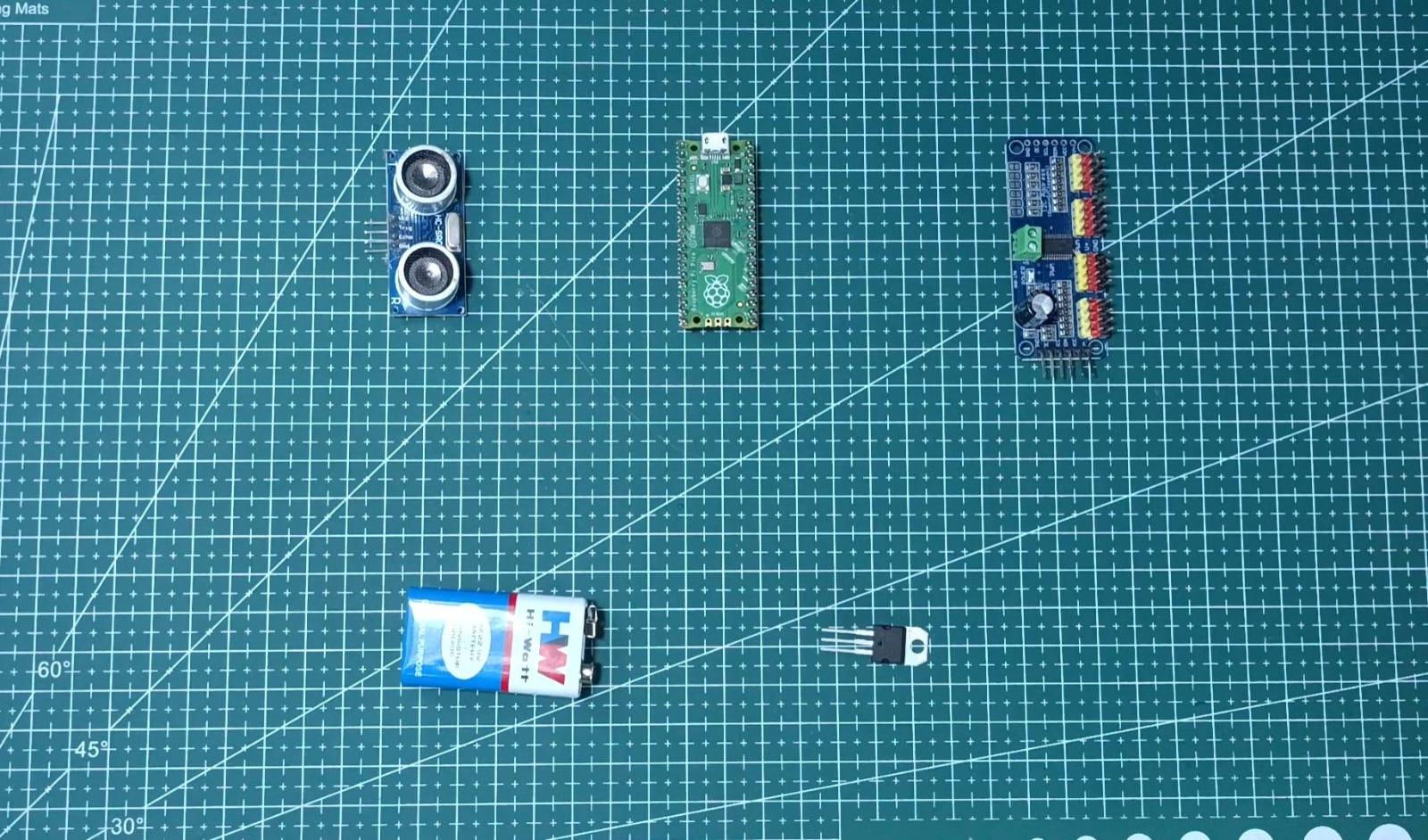
Electronic Components Required:
(International: amazon.com)
- Ultrasonic Sensor: https://tinyurl.com/k9rxwxbh
- Raspberry Pi Pico: https://tinyurl.com/4r6trm28
- Otto Robot 3D printed Body: https://tinyurl.com/2s4bkzam
- SG90 Servo Motor: https://tinyurl.com/3y9x3wsa
- PWM/Servo Driver I2C interface PCA9685: https://tinyurl.com/bdfz6bra
- LM7805 IC 5V: https://tinyurl.com/3x4nyr5z
- 9V Battery: https://tinyurl.com/4xa57zk7
(India: quartzcomponents.com)
- Ultrasonic Sensor: https://tinyurl.com/mryfn6xn
- Raspberry Pi Pico: https://tinyurl.com/4nnub457
- SG90 Servo Motor: https://tinyurl.com/e4j2tb8k
- PWM/Servo Driver I2C interface PCA9685: https://tinyurl.com/2zrbewh5
- LM7805 IC 5V: https://tinyurl.com/bh7uy9r2
- 9V Battery: https://tinyurl.com/4cjrbs65
- 9V Battery Snap Connector: https://tinyurl.com/uyevjxzm
Tools
- Soldering iron kit
- Wire cutter
- Glue gun
3D CAD for Otto Robot
Either 3D print the provided CAD design or purchase a pre-made version (available on Amazon).
Downloads
Assemble the Otto Robot
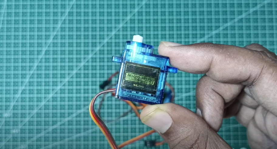
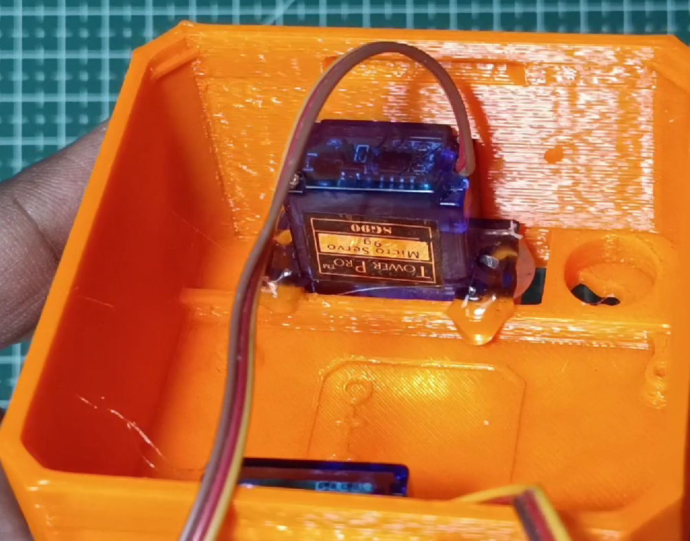
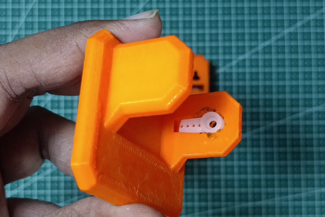
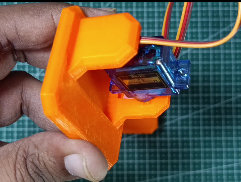
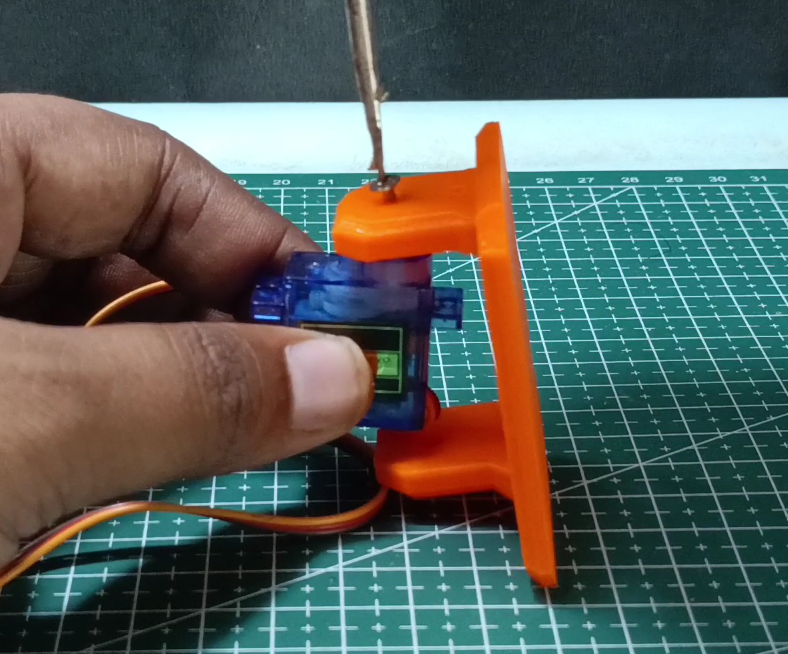
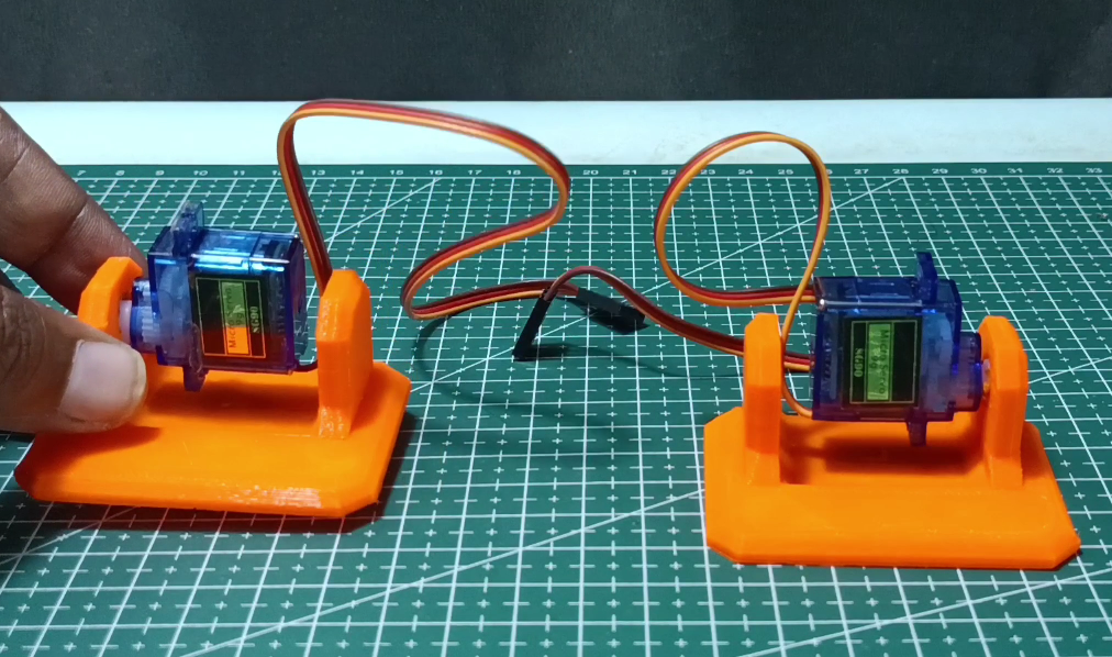
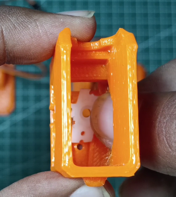
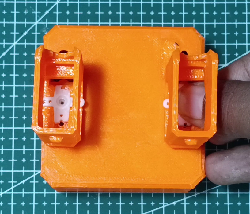
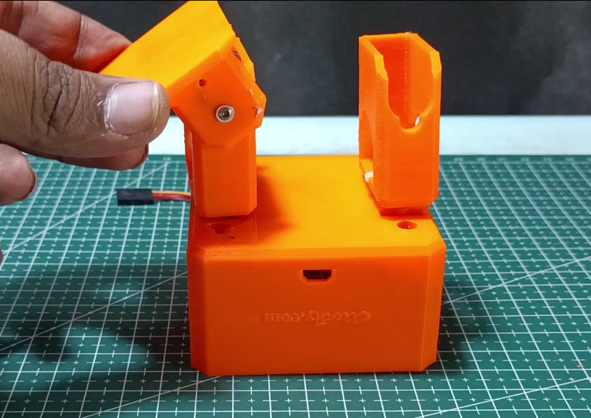
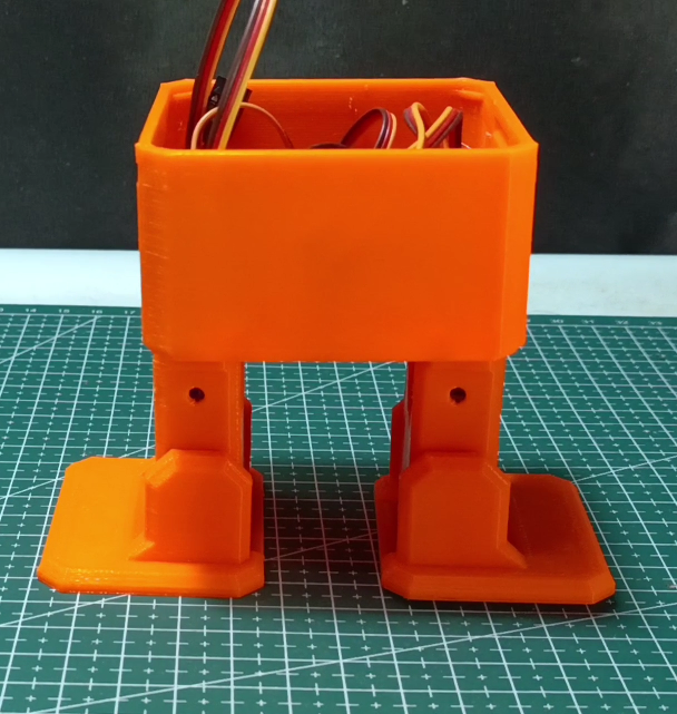
For this step, you'll need your 3D printed Otto Robot and 4 micro servo motors. Let's put them together:
Feet Assembly:
- Insert each micro servo into the feet slots. If they don't fit smoothly, carefully clean the area with a utility knife
- IMPORTANT: Test that each servo can rotate a full 90 degrees in both directions
- Once movement is verified, secure each servo using a small screw
Body Assembly:
- Place 2 micro servos into their designated spots in the robot's body
- Secure them with screws
- Attach the legs to the servo hubs
- Test leg rotation - ensure each can move 90 degrees in both directions from the body
- Once aligned, secure the legs using the small screws in the leg holes
Cable Management:
- Guide the servo cables through the body slots and leg holes
Pro Tip: Take extra care when routing the cables - proper cable management will ensure smooth movement and prevent wire damage during operation.
Leg & Foot Servo Motor Connection With PCA9685 16 Channel Servo Motor Driver
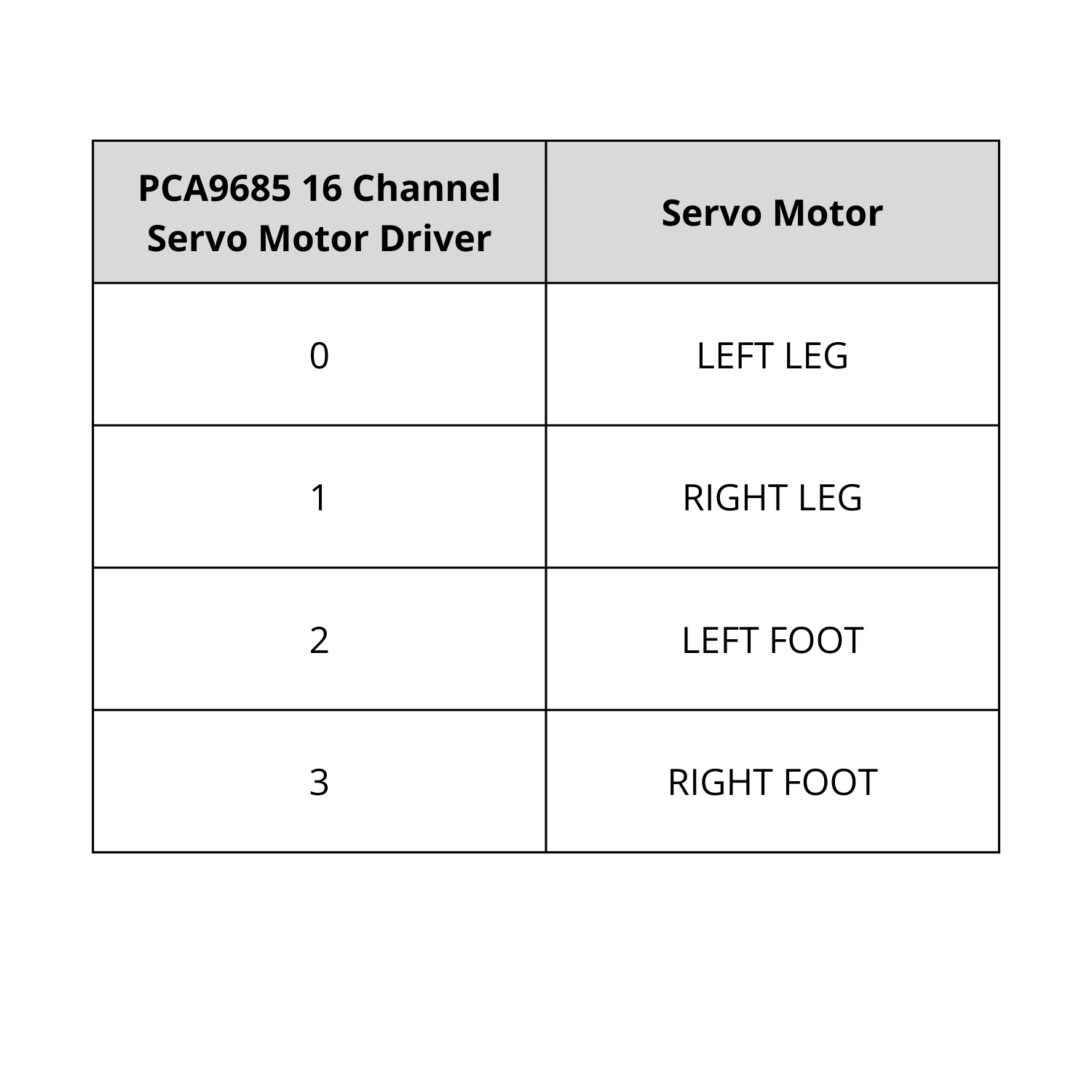
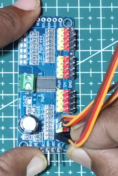
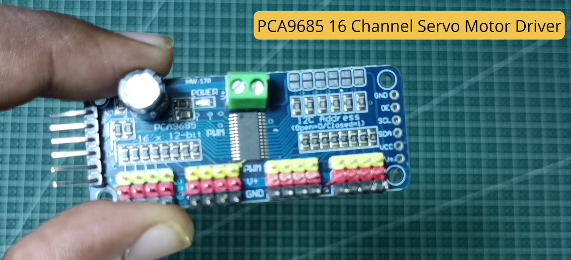
Using the connection diagram above, connect each servo motor to its designated channel on the PCA9685 16 Channel Servo Motor Driver:
- Left Leg → Channel 0
- Right Leg → Channel 1
- Left Foot → Channel 2
- Right Foot → Channel 3
Program the Raspberry Pi Pico
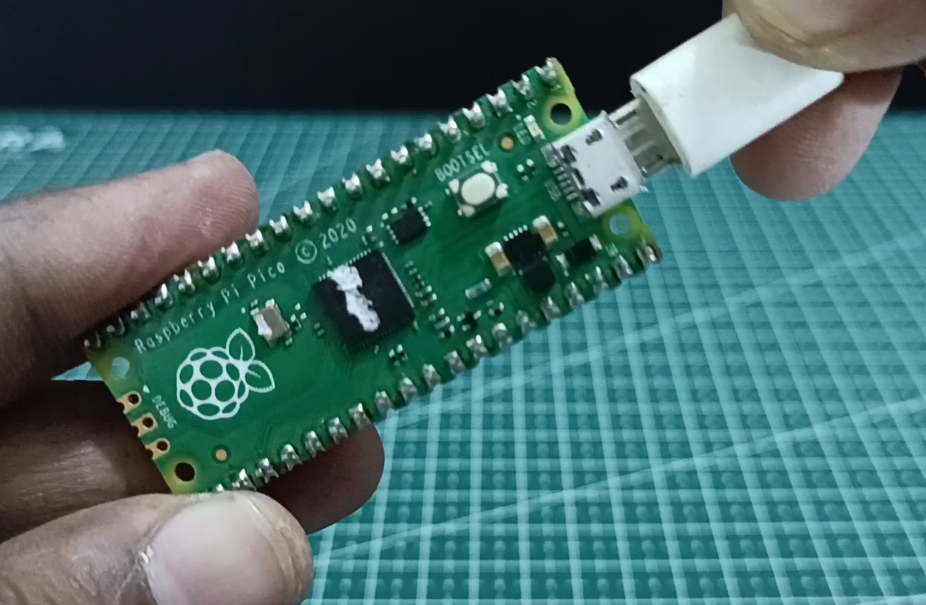
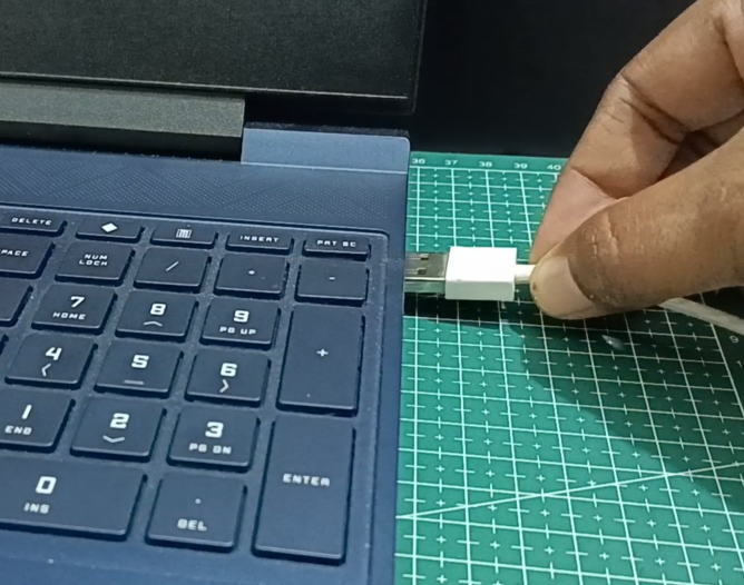
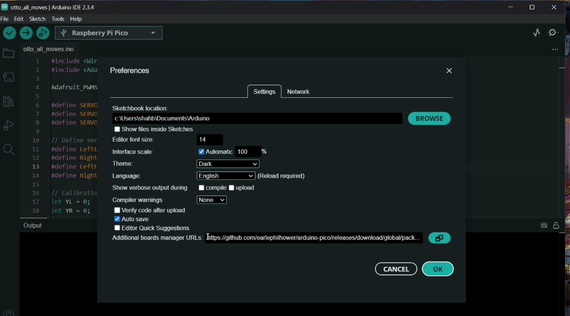
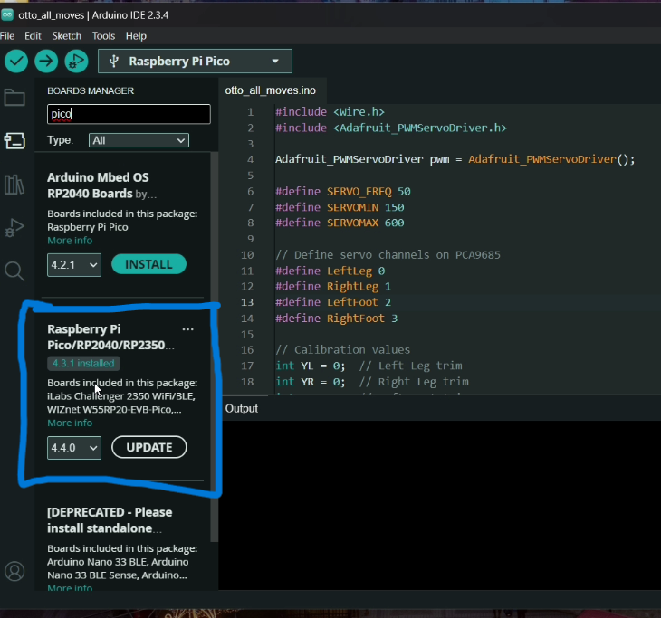
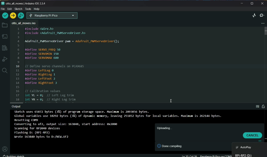
Before connecting the Raspberry Pi Pico to the circuit, ensure the code is uploaded to it. We will use the Arduino IDE to program the Raspberry Pi Pico, so make sure the Arduino IDE is installed on your device. Follow these steps:
- Connect the Raspberry Pi Pico to your device using a USB cable.
- Open the Arduino IDE, go to the "File" menu, and click on "Preferences."
- In the "Additional Board Manager URLs" field, paste the following URL: https://github.com/earlephilhower/arduino-pico/releases/download/global/package_rp2040_index.json
- Click "OK" to save the changes.
- Navigate to the "Board Manager," search for "Pico," and install the relevant board as shown in the attached image.
- Once the board is installed successfully, select the appropriate board and port from the Arduino IDE.
Then upload this code:
Note: For individual mode codes (walking, dancing, etc.), visit my GitHub repository: https://github.com/ShahbazCoder1/Otto-Robot-using-Raspberry-Pi-Pico-/tree/main
Final Circuit
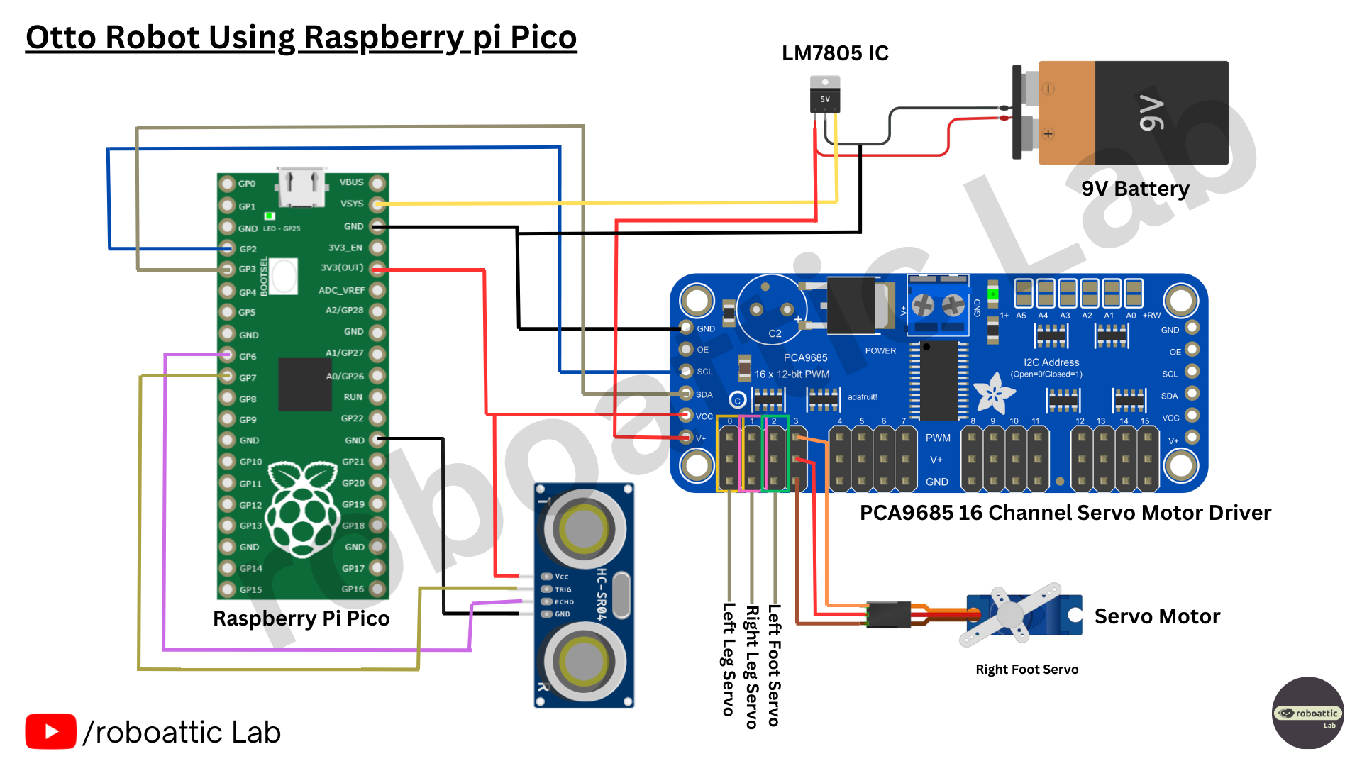
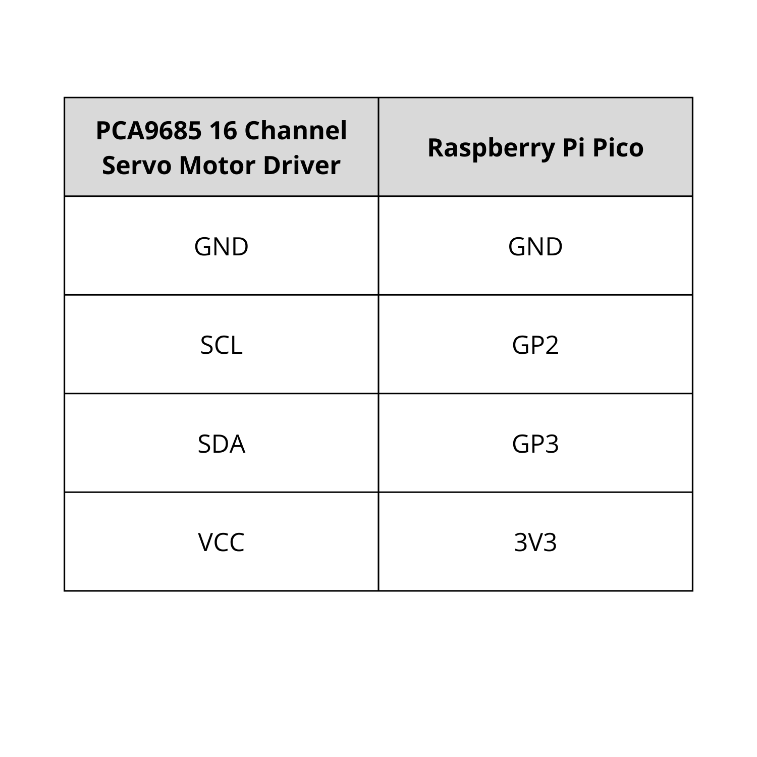
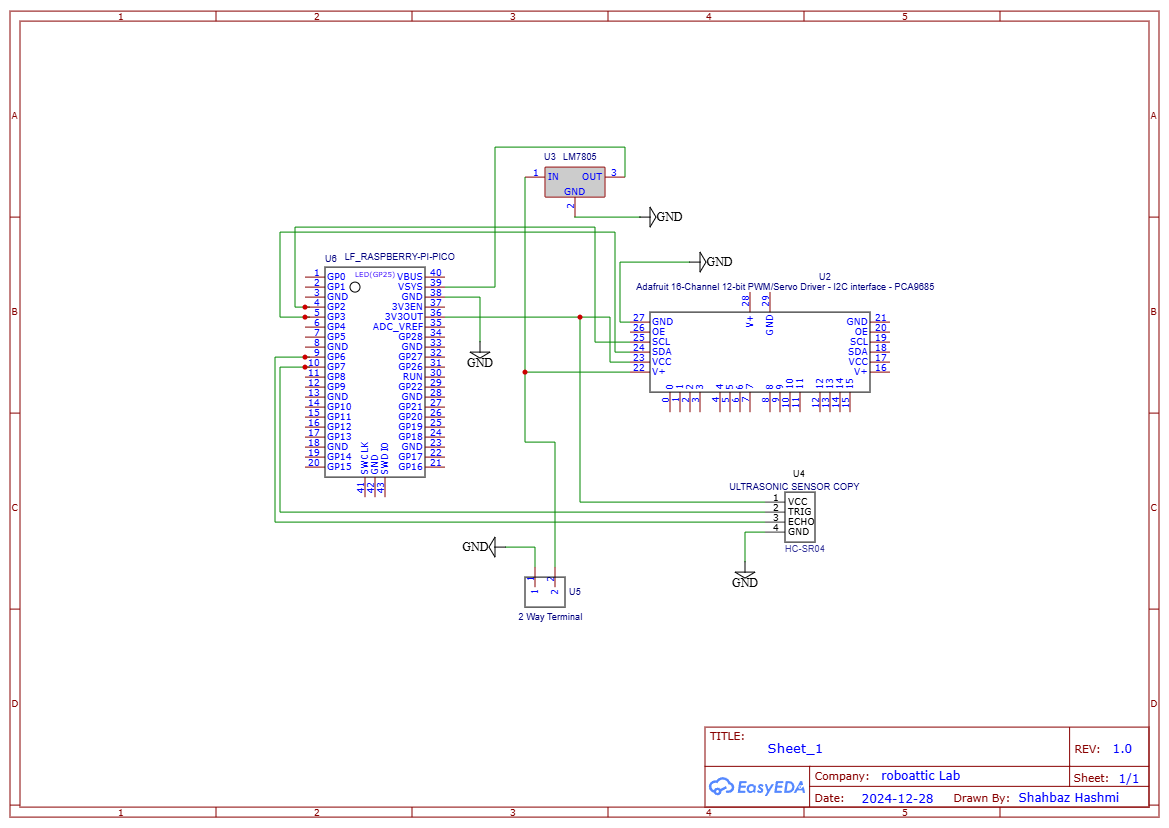
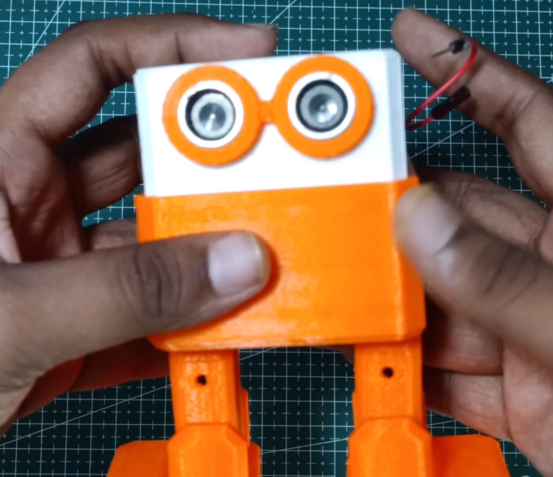
Using the circuit diagram above, connect the PCA9685 16-Channel Servo Motor Driver to the Raspberry Pi Pico as follows:
- GND → GND
- SCL → GP2
- SDA → GP3
- VCC → 3V3
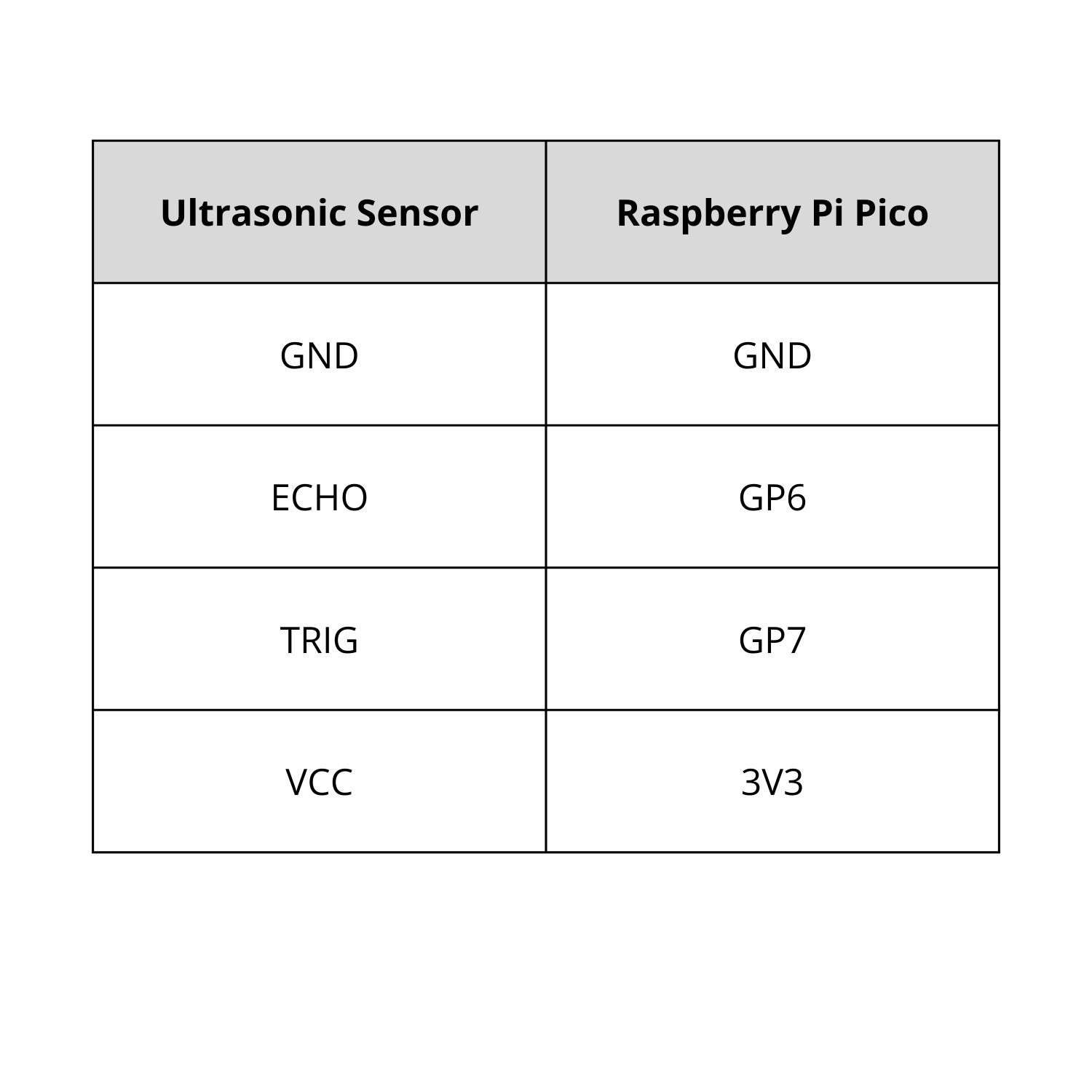
Next, connect the Ultrasonic Sensor to the Raspberry Pi Pico:
- GND → GND
- TRIG → GP6
- ECHO → GP7
- VCC → 3V3
Refer to the circuit diagram to create the power source using an LM7805 IC and a 9V battery.
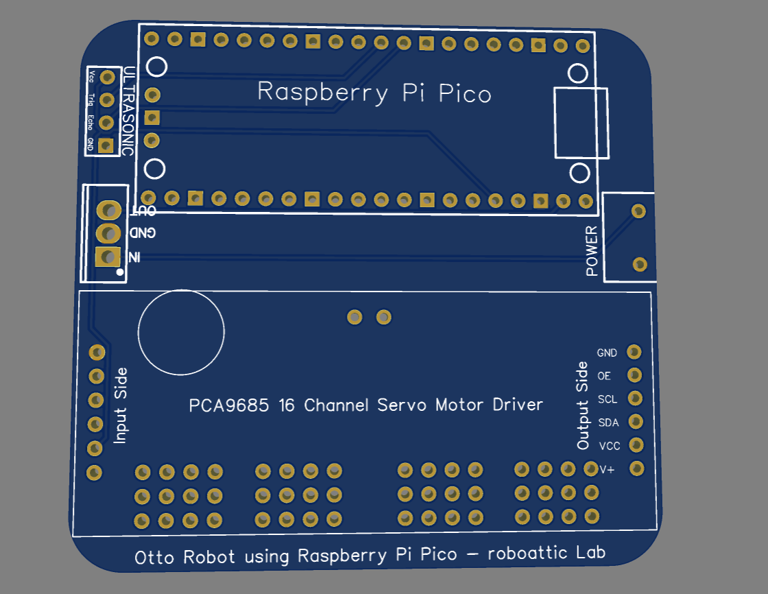
Pro Tip: To simplify the connections and reduce wiring complexity, consider using a PCB board, as we have done, to streamline the circuit assembly. Gerber File: https://drive.google.com/file/d/1AsC0VhEfRiCAE09JpRLL3uXAu8ZMR3mb/view?usp=drive_link
Working Video and Tutorial
A demonstration video of this project can be viewed here: Watch Now
Thank you for your interest in this project. If you have any questions or suggestions for future projects, please leave a comment and I will do my best to assist you.
For business or promotional inquiries, please contact me via email at Email.
I will continue to update this instructable with new information. Don’t forget to follow me for updates on new projects and subscribe to my YouTube channel (YouTube: roboattic Lab) for more content. Thank you for your support.