How to Make a Mobile Base for a Kuka KR 100
by TheKuka in Workshop > Metalworking
1606 Views, 3 Favorites, 0 Comments
How to Make a Mobile Base for a Kuka KR 100
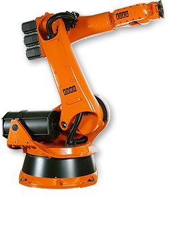
This instructables is to show you how to make a mobile platform for a Kuka KR 100.
So if you have a spare KR 100 laying around and it needs to be move, or you have some disposable money to buy a KR 100 that needs a platform these steps will help you build the platform.
Note that some of these can be substituted for other types. For example the caster wheels can be larger and have a higher load rating. The grade for the medium strength screws and be better or worse. The thickness of the square tubing can be thicker. We chose the most optimal and cost effective materials to build our version of the platform.
The list of materials needed can be seen below
- 3 Square Tubing ( 3"x3"x0.120" x 8' )
- 4 Waxman Titan 8 inch Polyurethane Caster Swivel 900 lb ( 8" Wheel )
- 1 Carbon Steel ACME Lead Screw ( 1"-10 x 3' )
- 4 Carbon Steel ACME Hex Nut ( 1'-10 )
- 8 Medium-Strength Grade 5 Steel Hex Head Screw ( 1"-8 x 4.5" Partially Treaded )
- 8 Medium-Strength Grade 5 Steel Hex Head Screw ( 1"-8 x 2.5" Fully Treaded )
- 1 Medium-Strength Steel Hex Nut ( 10 Pack) ( 1"-8 )
- 1 A36 Steel Plate ( 1' x 2' )
- 1 Low Carbon Steel Round Tube ( 0.188" Wall , 1-1/4" OD, 3' Long )
- 1 Low Carbon Steel Round Tube ( 1/4" Wall, 1-1/2" OD, 1' Long )
- 1 Vermont American1"- 8 Tap ( 1"-8 )
SolidWorks Files
Downloads
Create Templates From CAD Files (Optional)
This is an optional step but it well help. Once the CAD files for the Kuka Robot are complete, use them to create templates. Create a template for a side of the octagon base, angle between octagon base sides, and the lifting arms. These templates will help with the manufacturing of the different parts needed for assembly by providing exact and consistent measurements.
Cut Square Tube to Take Care of the Bulk of Cutting
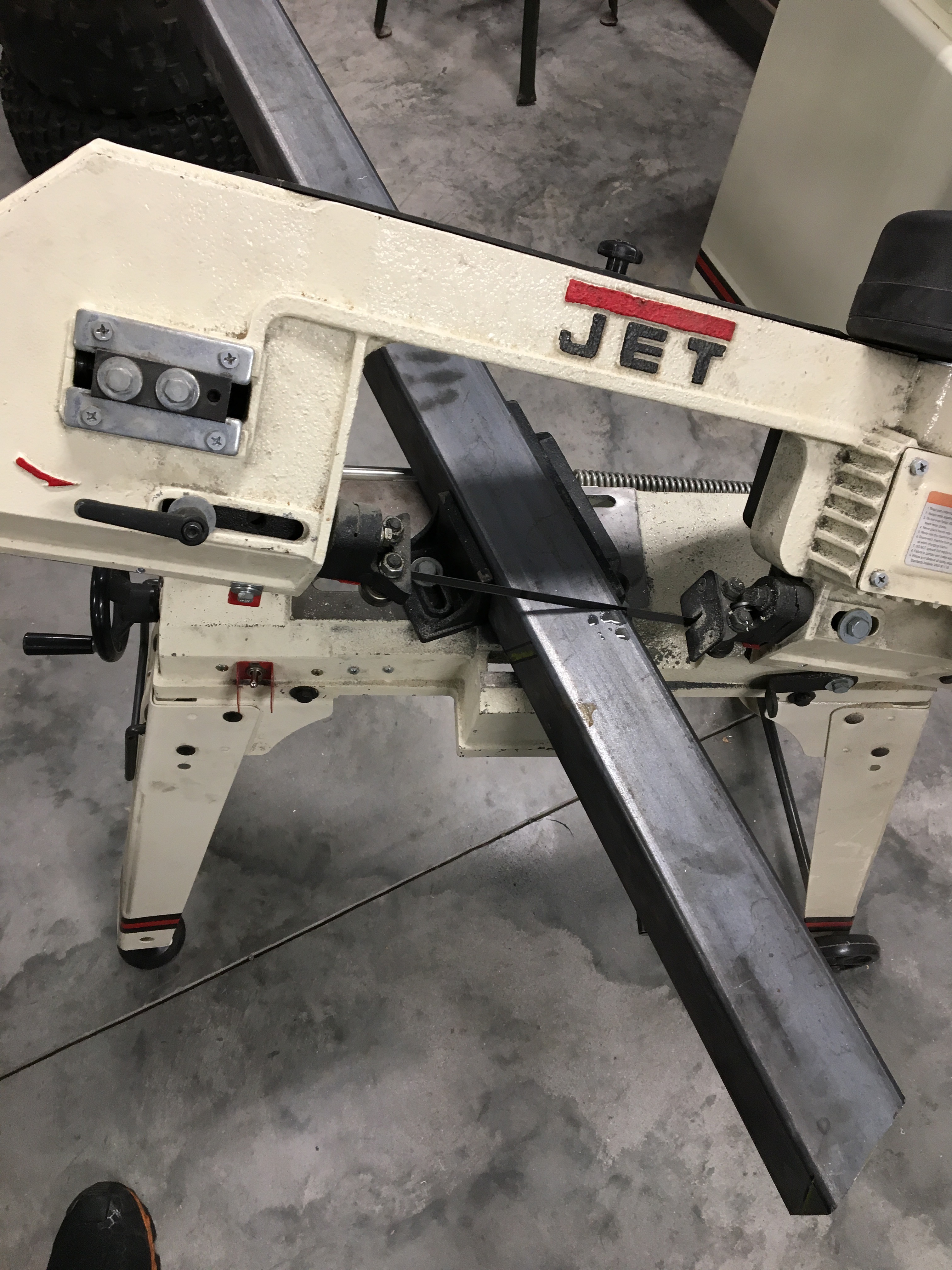
With the template made from the CAD model, use the template to outline each side on the square tubing and mark them for cutting. Cut all eight sides of the octagon using the horizontal band saw. Cut the legs, upright, upright connectors, coupler, and plates to couplers as well.
Check Octagon Dimensions
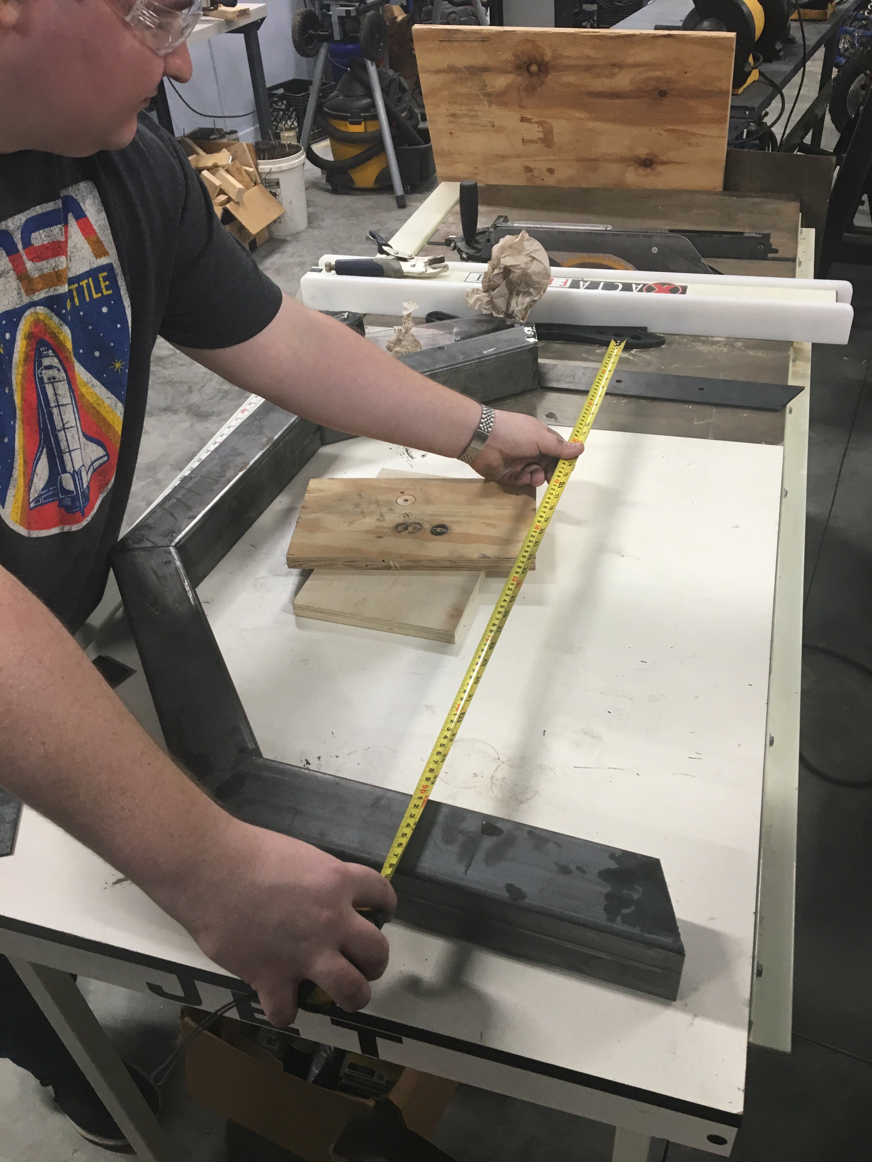
Once all 8 sides are cut, grind down all of the rough edges with a hand grinder. Put all eight sides in place and use a tape measure to confirm the dimensions match the CAD model. Use the angle template to check the angles between each side. If the dimensions don't match and there are gaps, use a grinder to remove excess material.
Prep Octagon Sides for Welding
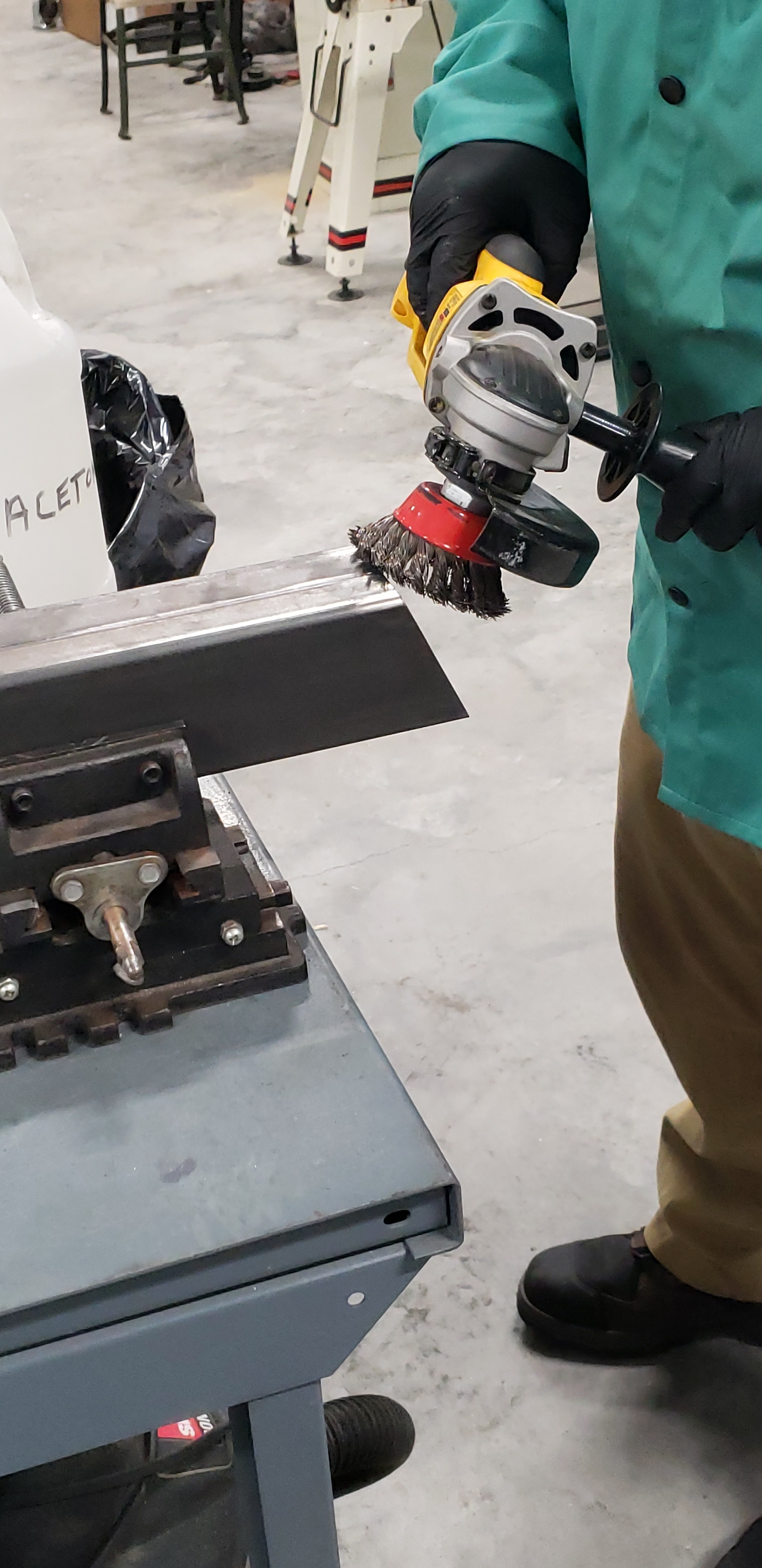
Once the octagon dimensions are correct, the sides need to be prepped for welding. Use a wire brush attachment on an angle grinder to make sure the edges are clean and free of chips.
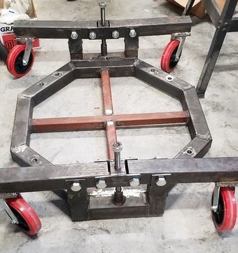
Weld the Octagon
Weld all of eight of the trapezoid pieces that was cut to make an octagon using a MIG welder or any type of preferable welding types.
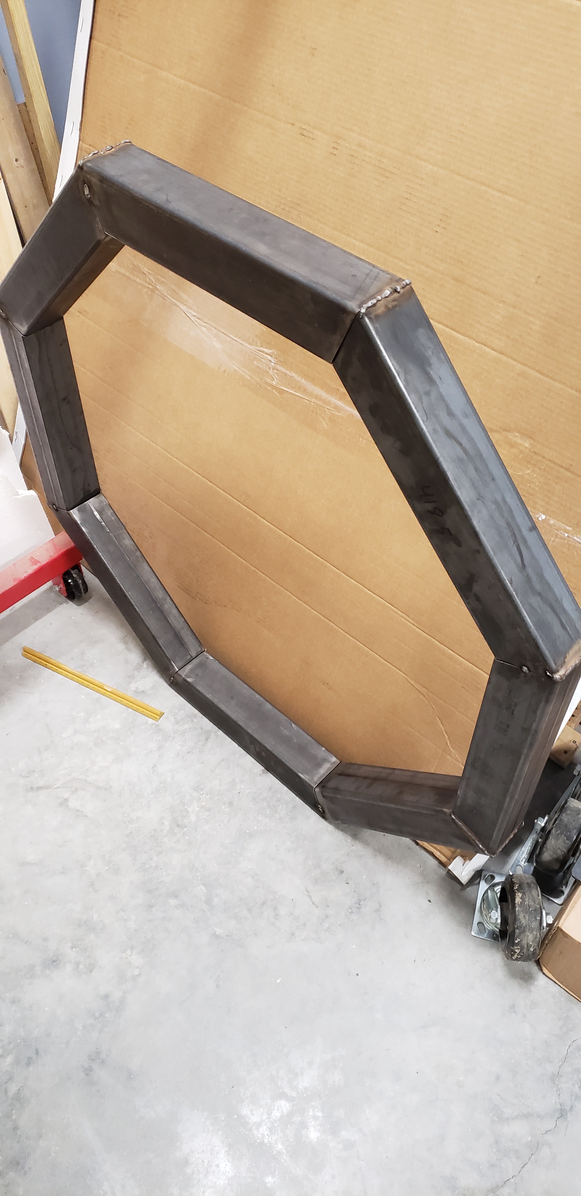
Clean Up the Octagon Welds
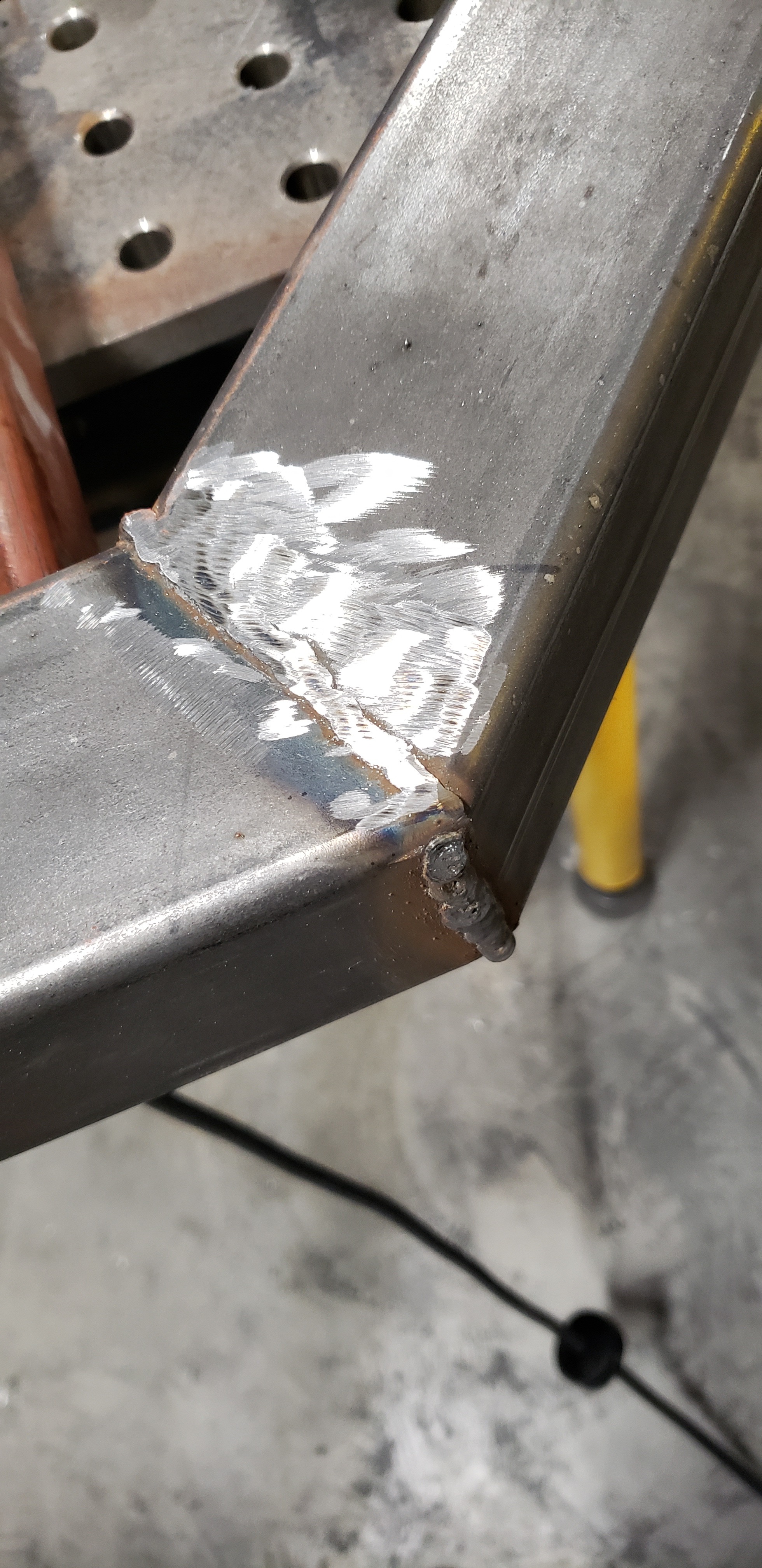
After the octagon is completely welded. Use an angle grinder to grind down all the welds making the top and bottom of the octagon completely flat and smooth.
Cutting the Cross Brace
Once the outer frame was constructed we need to keep the shape stiff. Cutting a 1/4" thick 1.5"x1.5" to a length the inner diameter of the octagon and another two pieces for the cross in the cross brace. Remove spurs and polish the ends in preparation for welding.
Positioning the Cross Brace
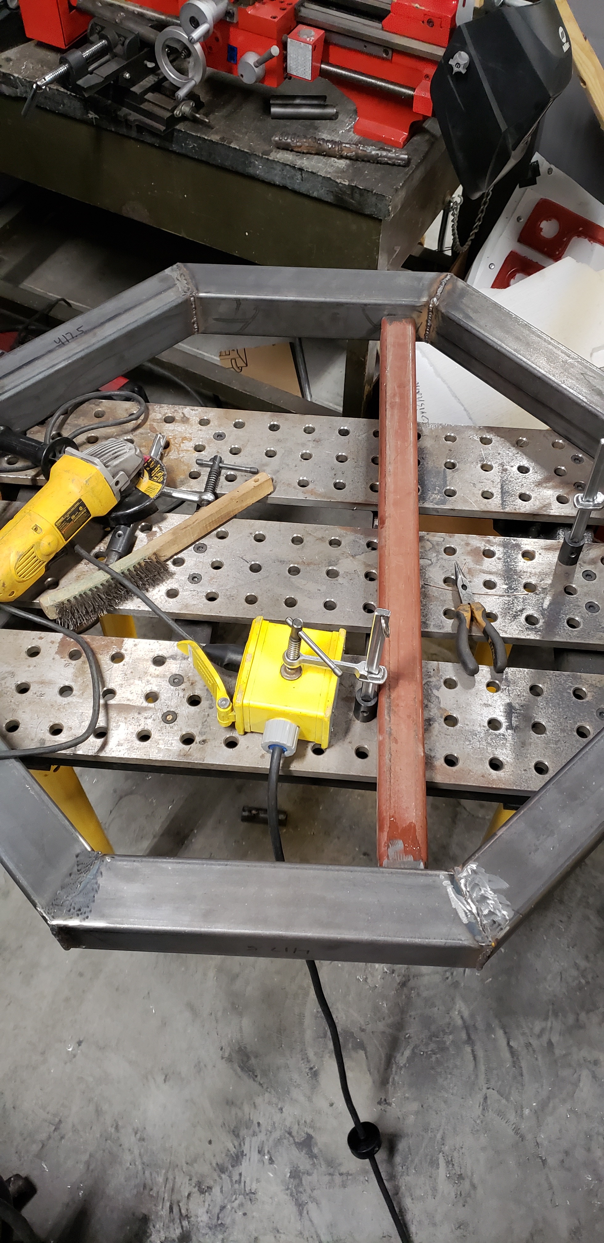
Centering the foundation of the cross brace is a large part of stable engineering design. Center the cleaned cross brace bars among the octagon shape.
Welding the Cross Brace
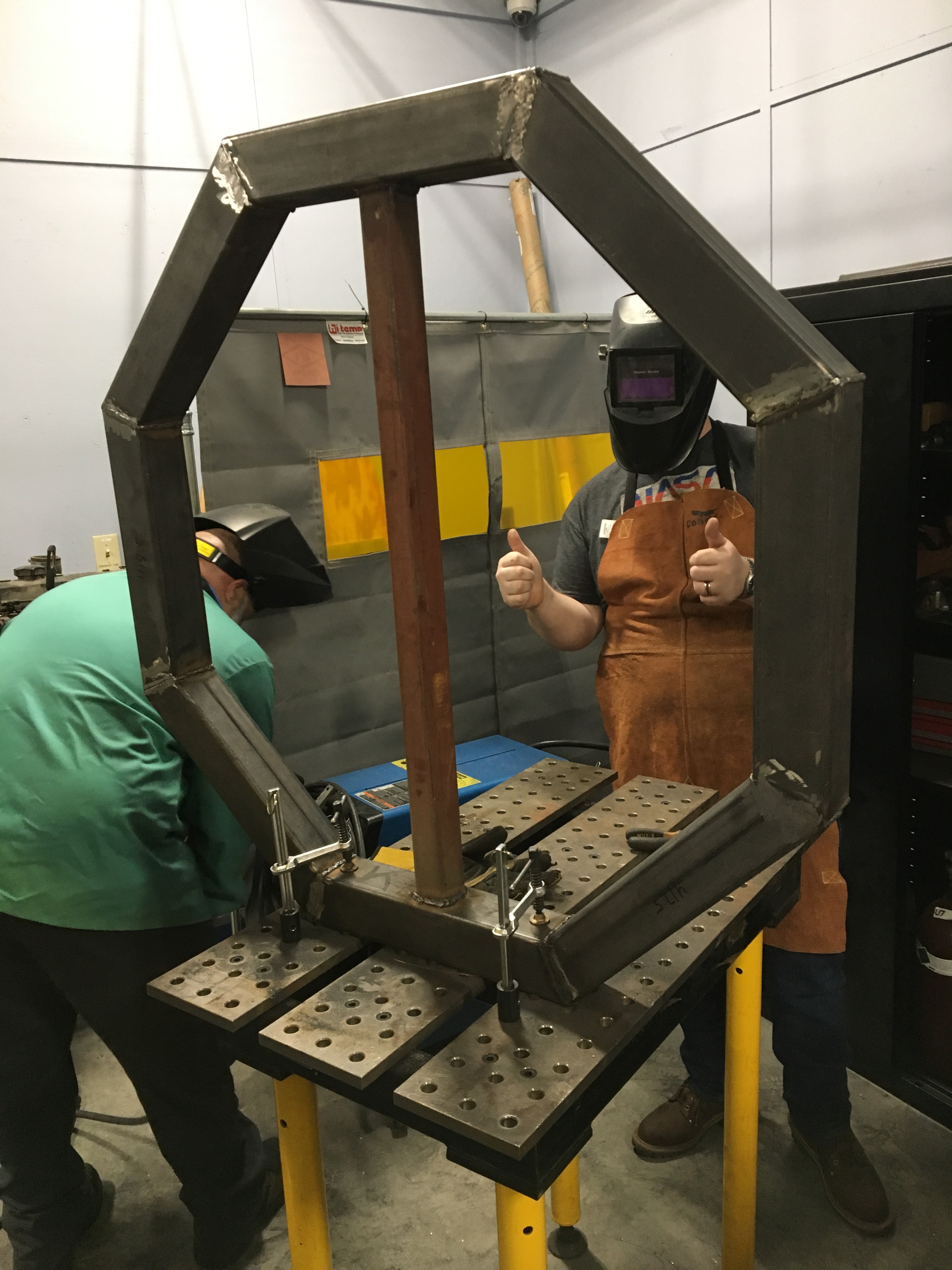
Once alignments are done and the cross brace is centered weld it in place covering all seams.
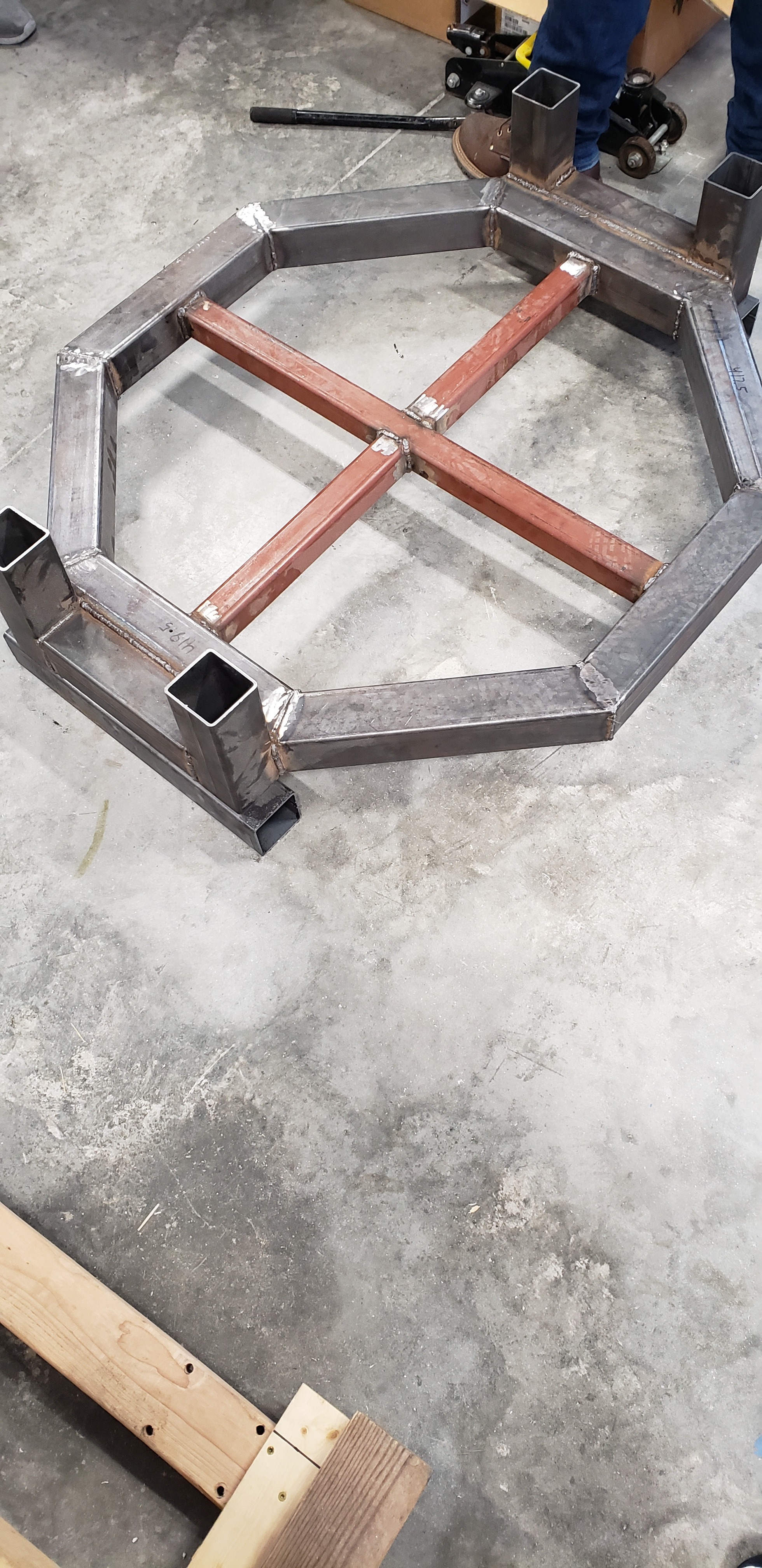
Cross Brace
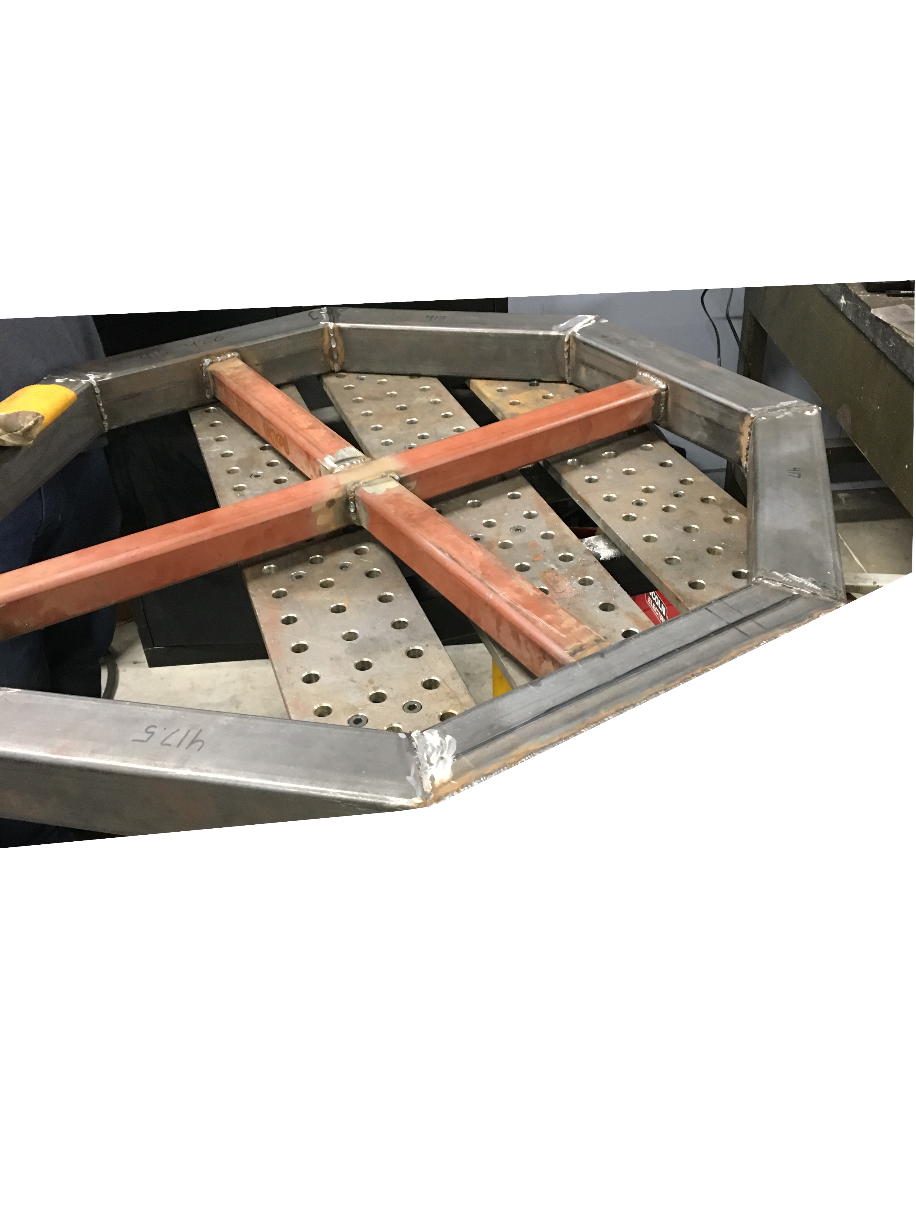
Weld on the the two other cut out pieces to form the cross brace foundation. Make sure to center this too.
Welding the Uprights to Platform
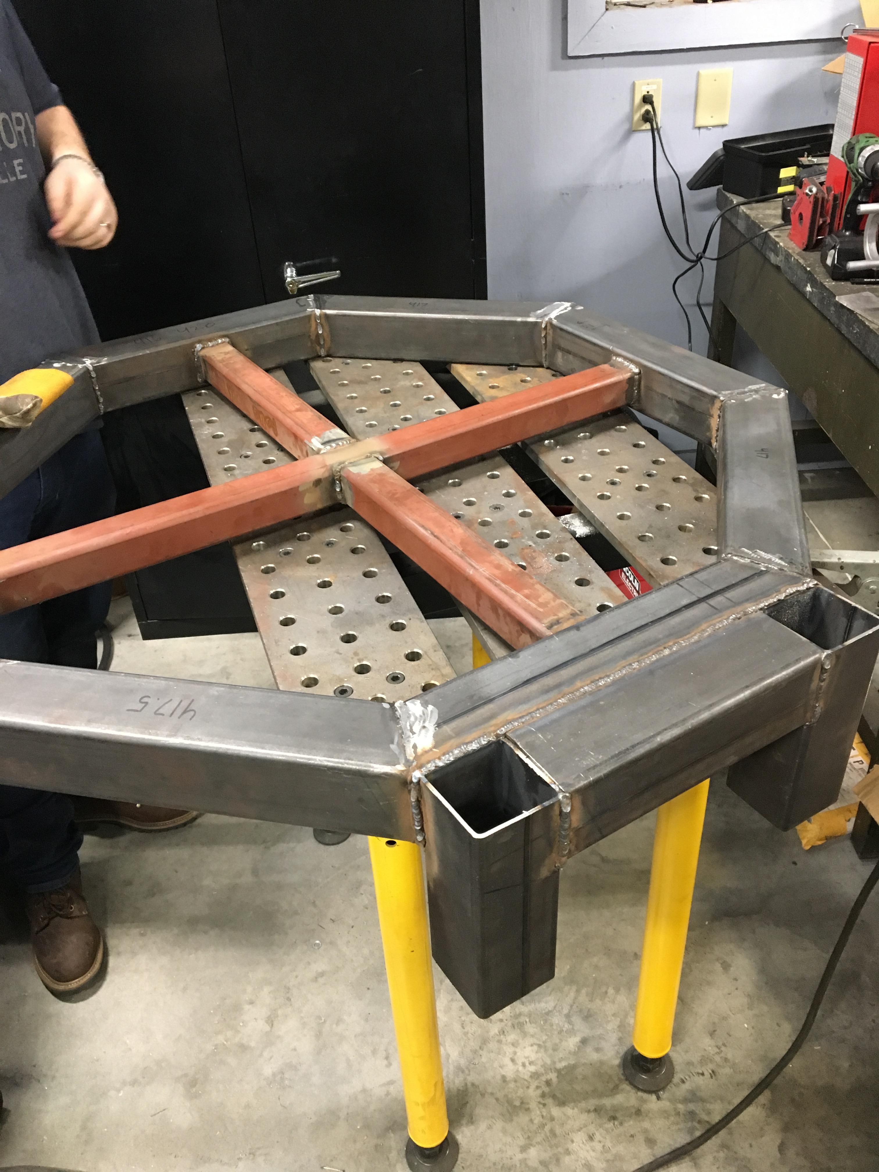
The two uprights and upright connectors will create a U shape. Weld the U shaped assembly onto one side of the octagon preferably on a cross leg. Keep surfaces that will touch the floor flush.
Platform With Welded Uprights
Weld the other upright on the opposite side of the first. Use the same procedure as the other upright.
Drilling Hole on Coupler Plate
Drill two 1 inch diameter hole down the center line and 1.5 inches away from each sides of the plate. Do this for 4 plates.
Coupler
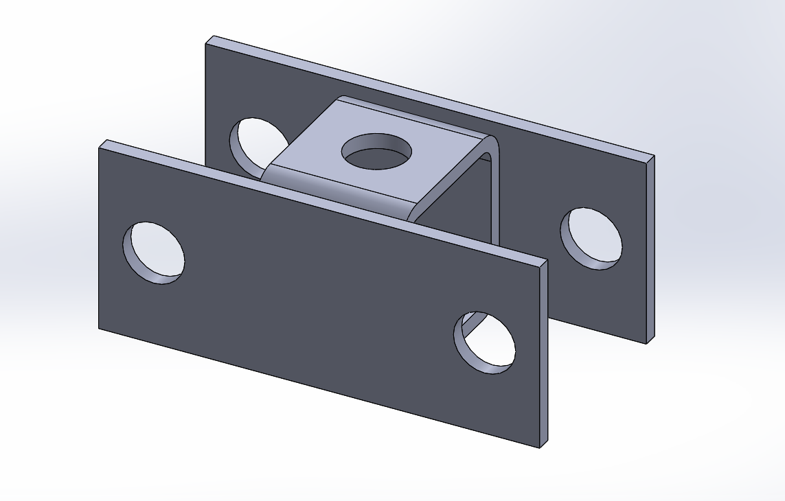
Weld the cleaned and deburred coupler plates and coupler body together. Center up the body of the coupler and face the open ends towards the holes in the coupler plates.
Welding Acme Nut to Coupler
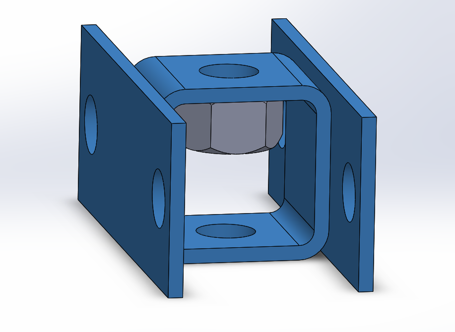
Weld the acme nut to the inside of the coupler body, centric to the hole drilled in the tube.
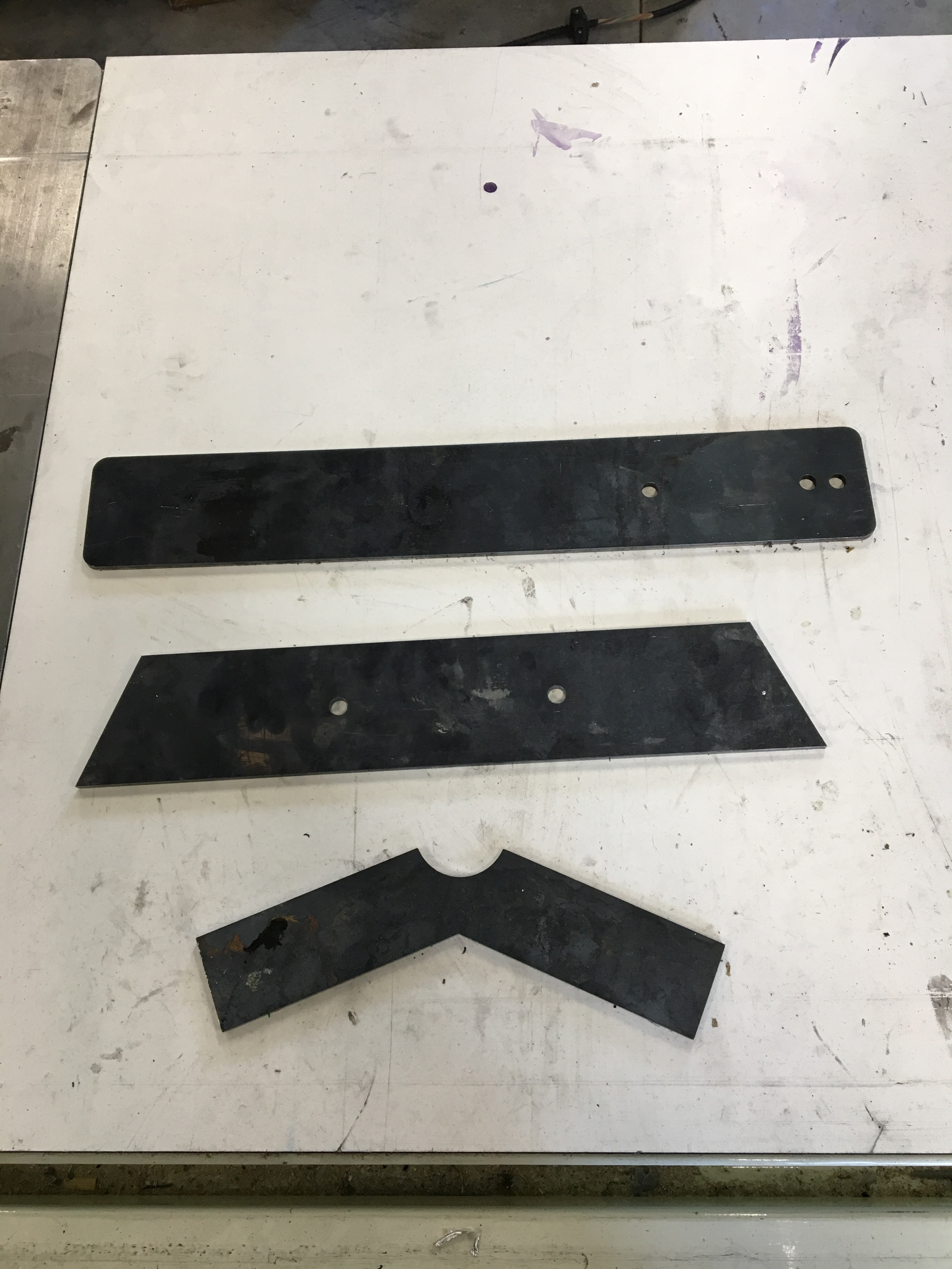
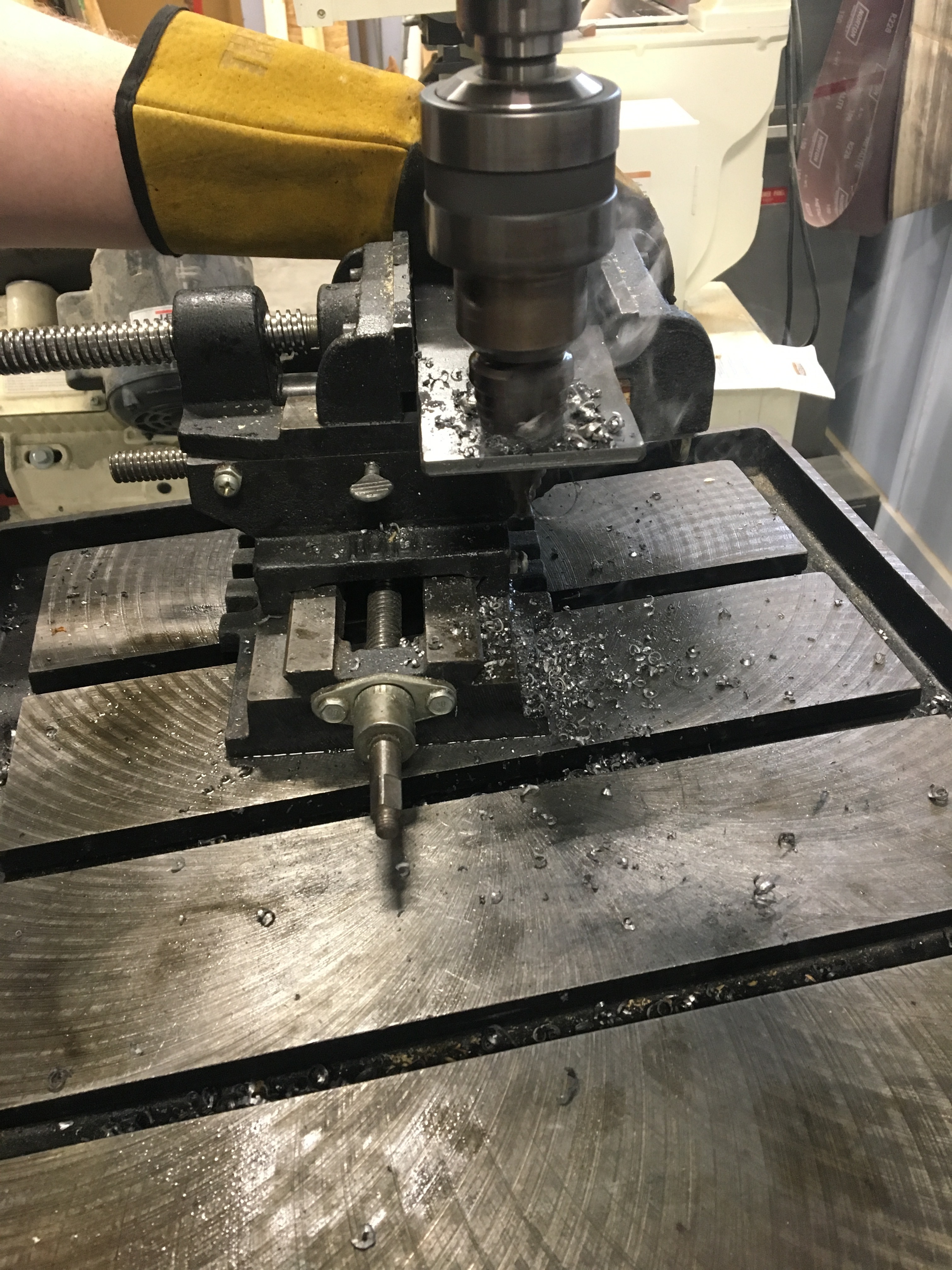
Milling Slot on Lifting Arm
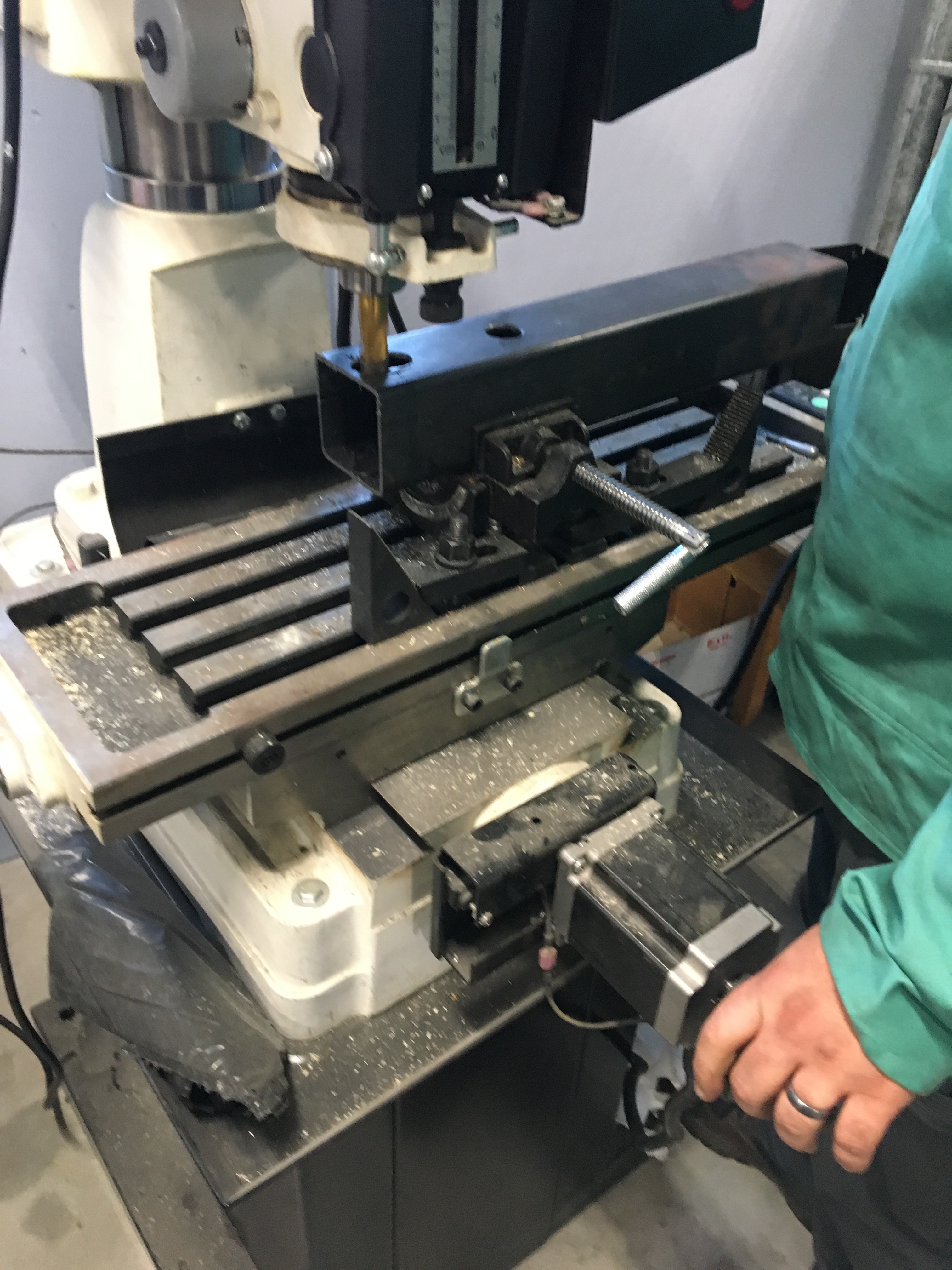
Drill two 1" holes 1.5" apart and use a manual milling machine to carve out the oval slots. You can use a CNC to do this process as well.
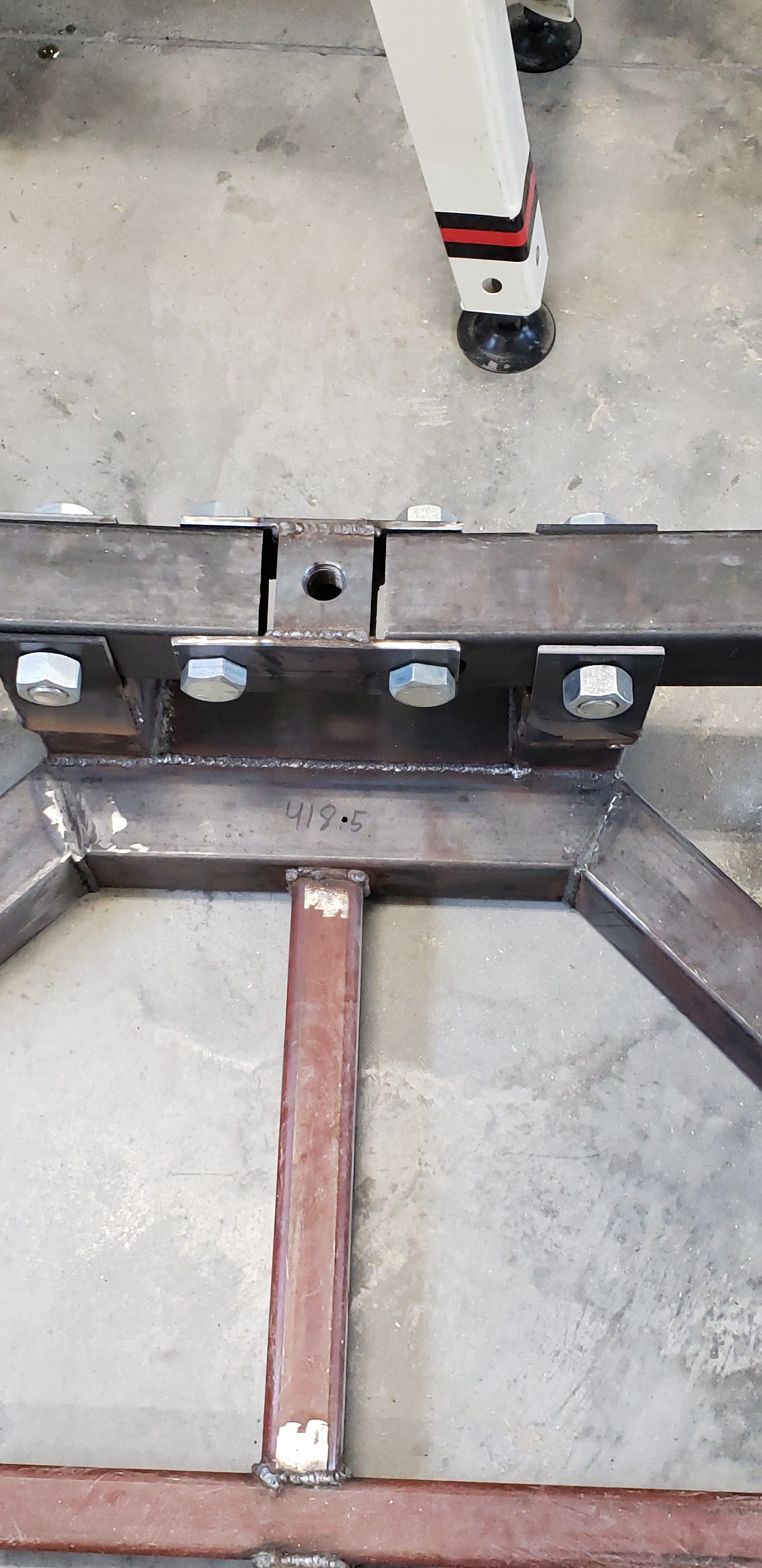
Welding Plates to Uprights
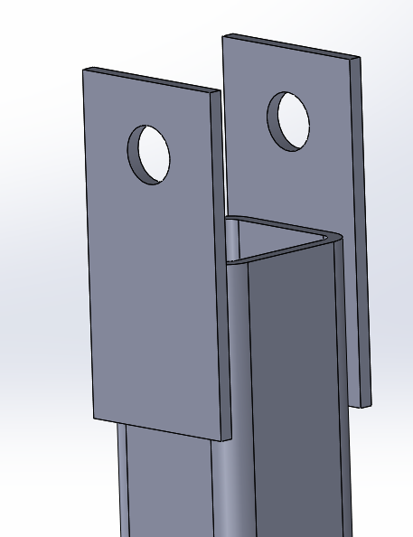
For the eight plates with 1 inch holes that are 1.5 inches away from the edge, weld two plates (hole side up) parallel to each other on either side of the tube and have the plates parallel to the octagon side the upright is welded to. Do this for 4 upright legs.
Mounting Lifting Arm to Platform
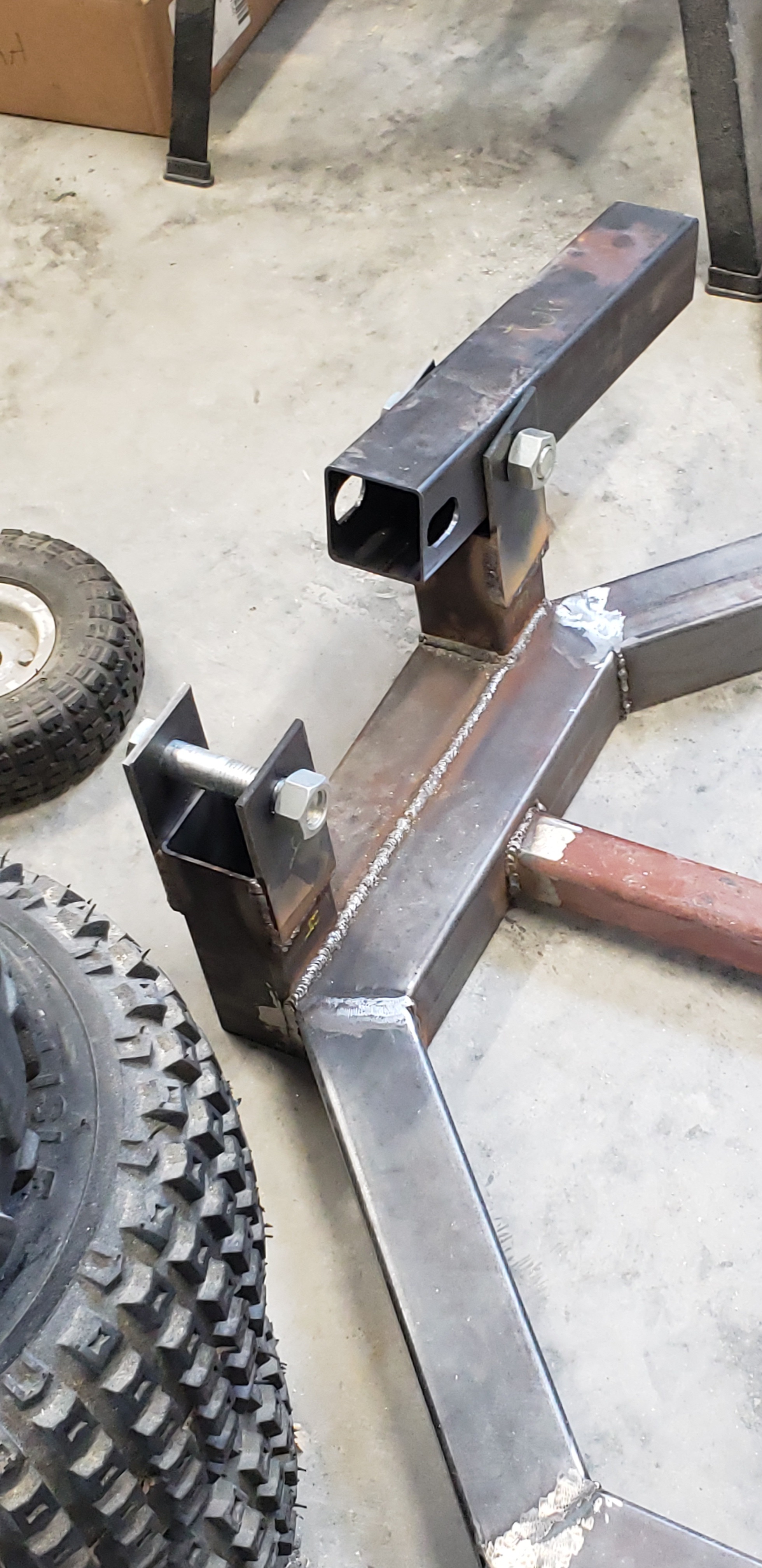
Attach the leg of the Kuka robot between the plates on the assembly to test fit and hole fit for the bolt.
Assembling Both Lifting Arms and Coupler to Platform
Assemble both legs symmetrical about the couple and place them between the plates on the upright to test the tolerances of each piece in the assembly using bolts to keep together.
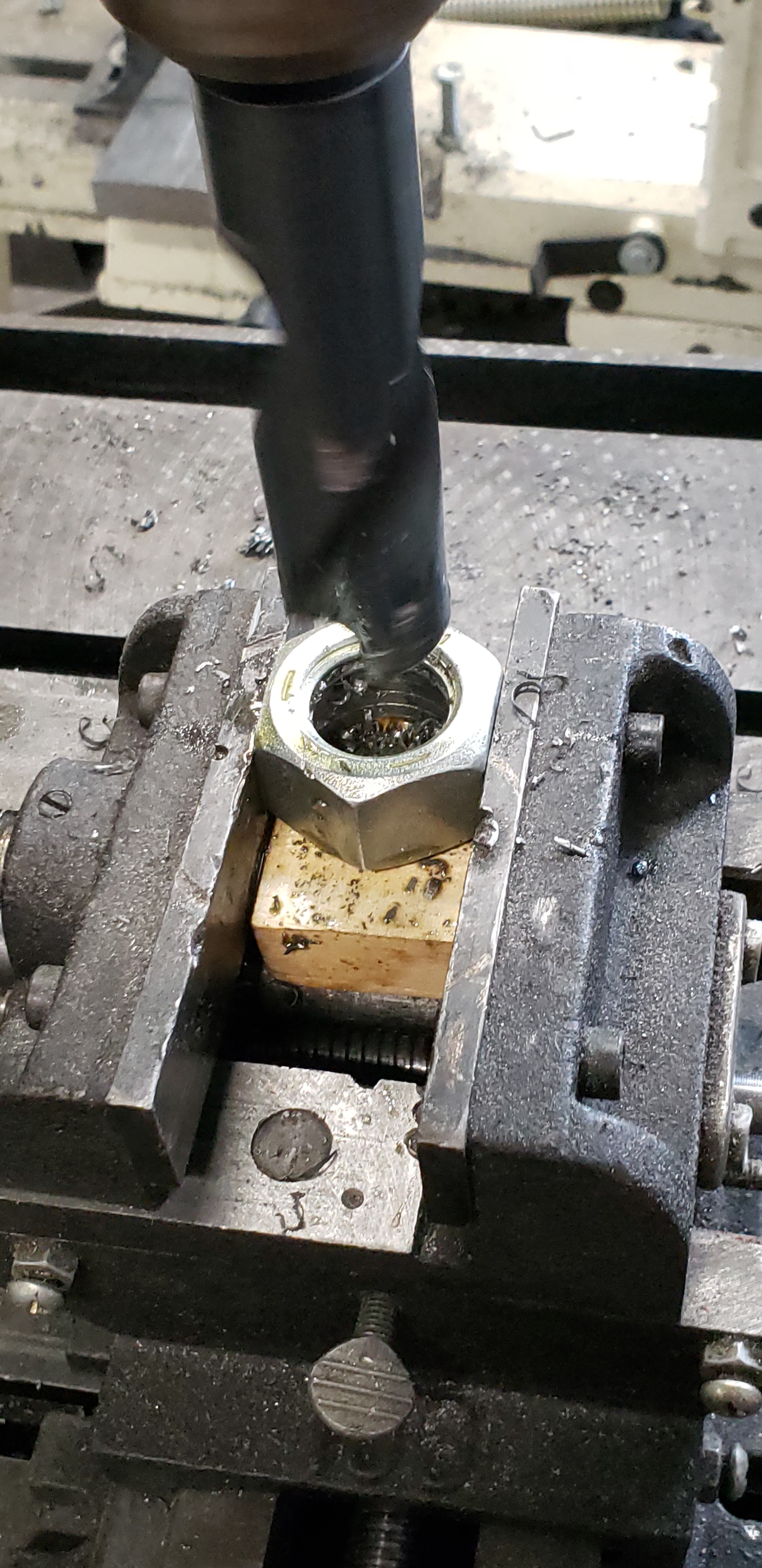
Checking the Nuts and Bolts
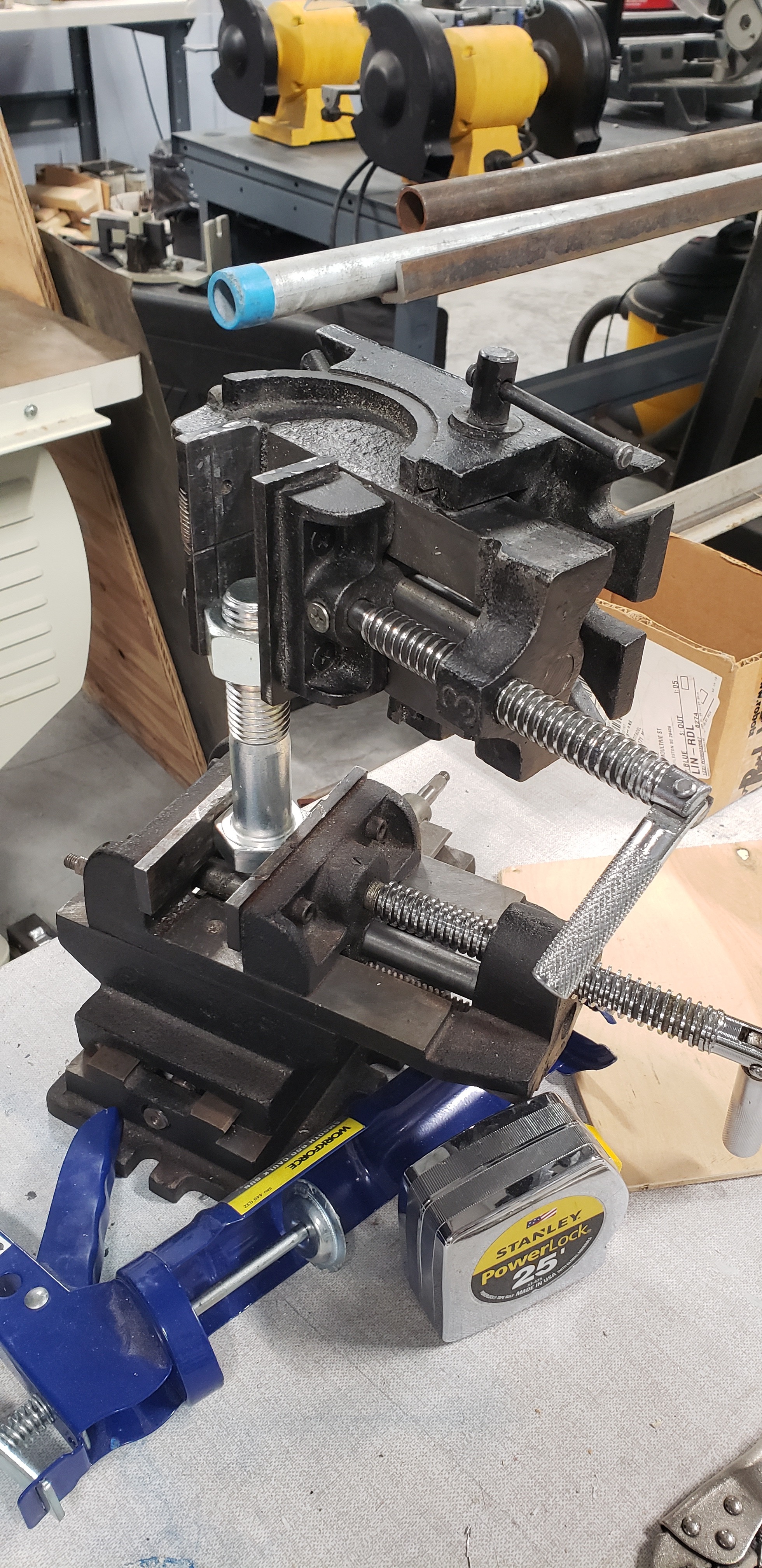
Some nuts and bolts did not come perfectly manufactured as we found in calibration so we were left to our devices to clean out and mate the nut to its bolt. Depending on how well equipped your shop is, the outcome would be much better or worse than what is shown.
Tapping the Bungs
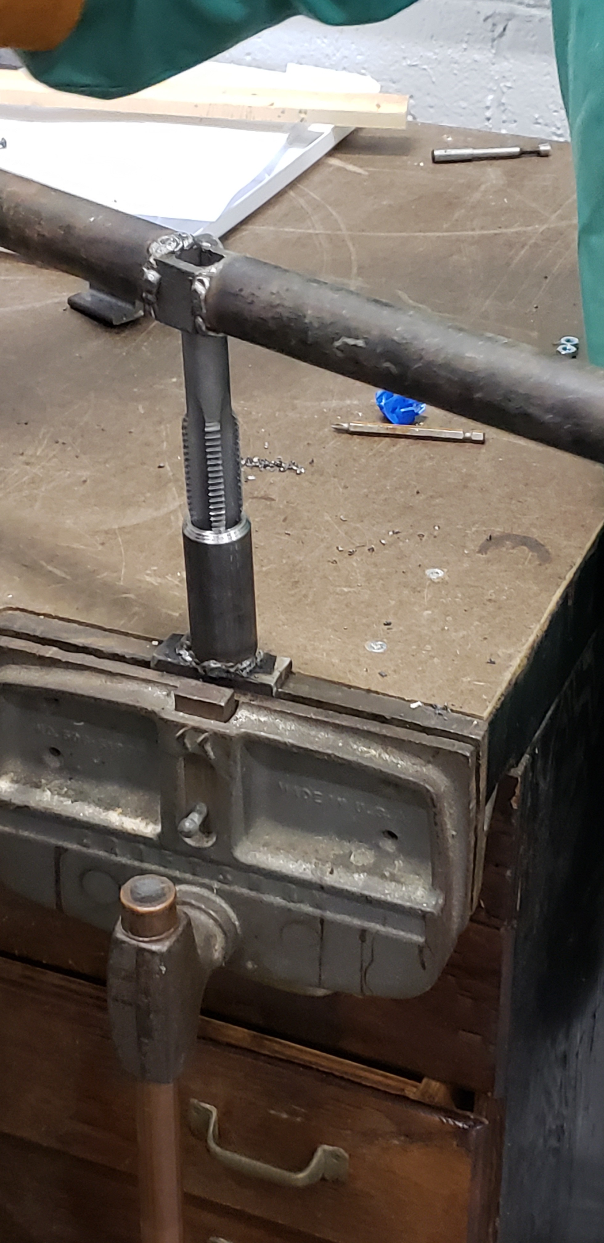
For the 8 bungs, tap them with the help of two people and a 6' diameter tapping rod. Check with other people while using scrap parts in the shop. You can tap them differently but this is what we had to do.
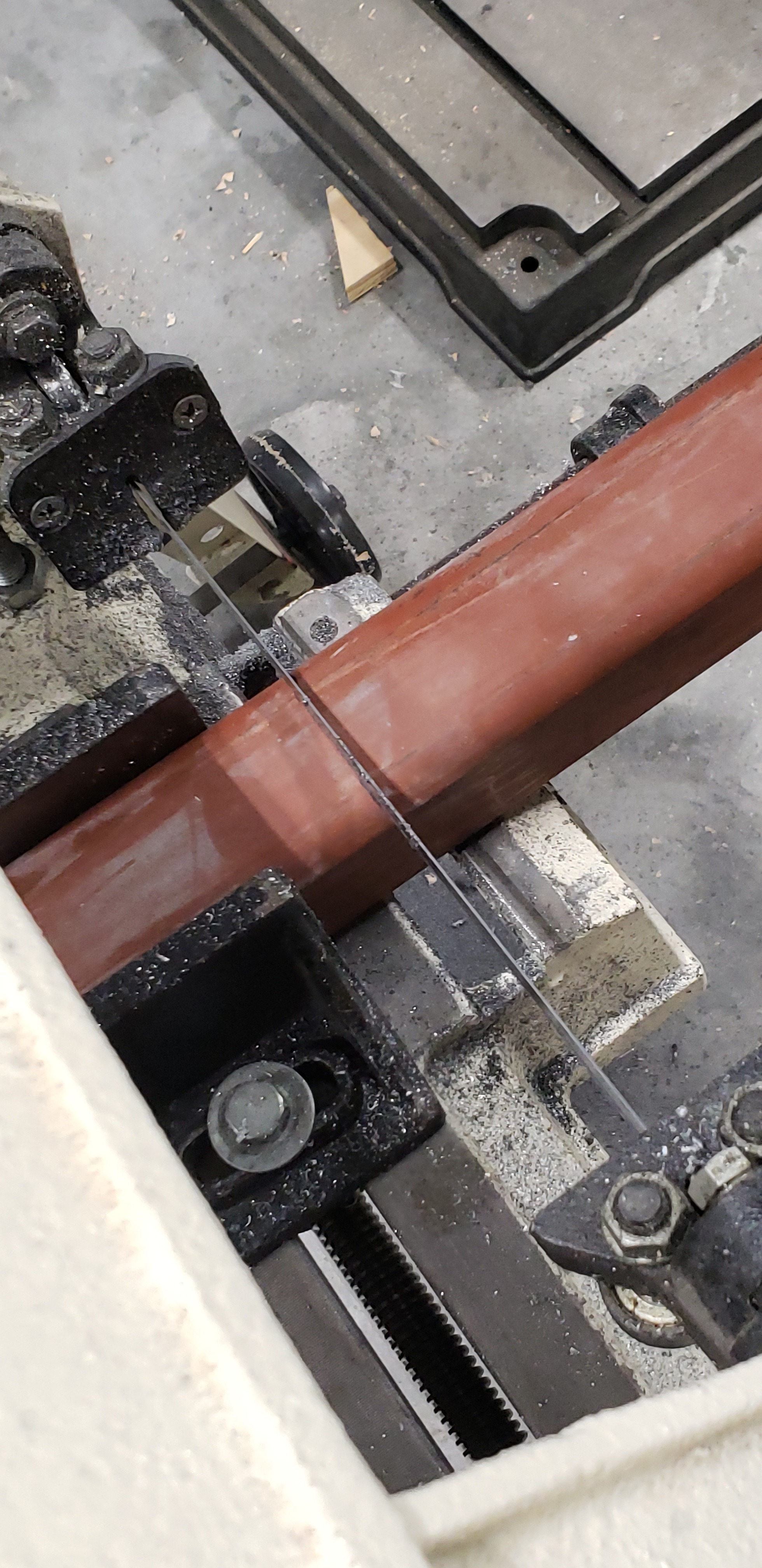
Cutting Acme Screw
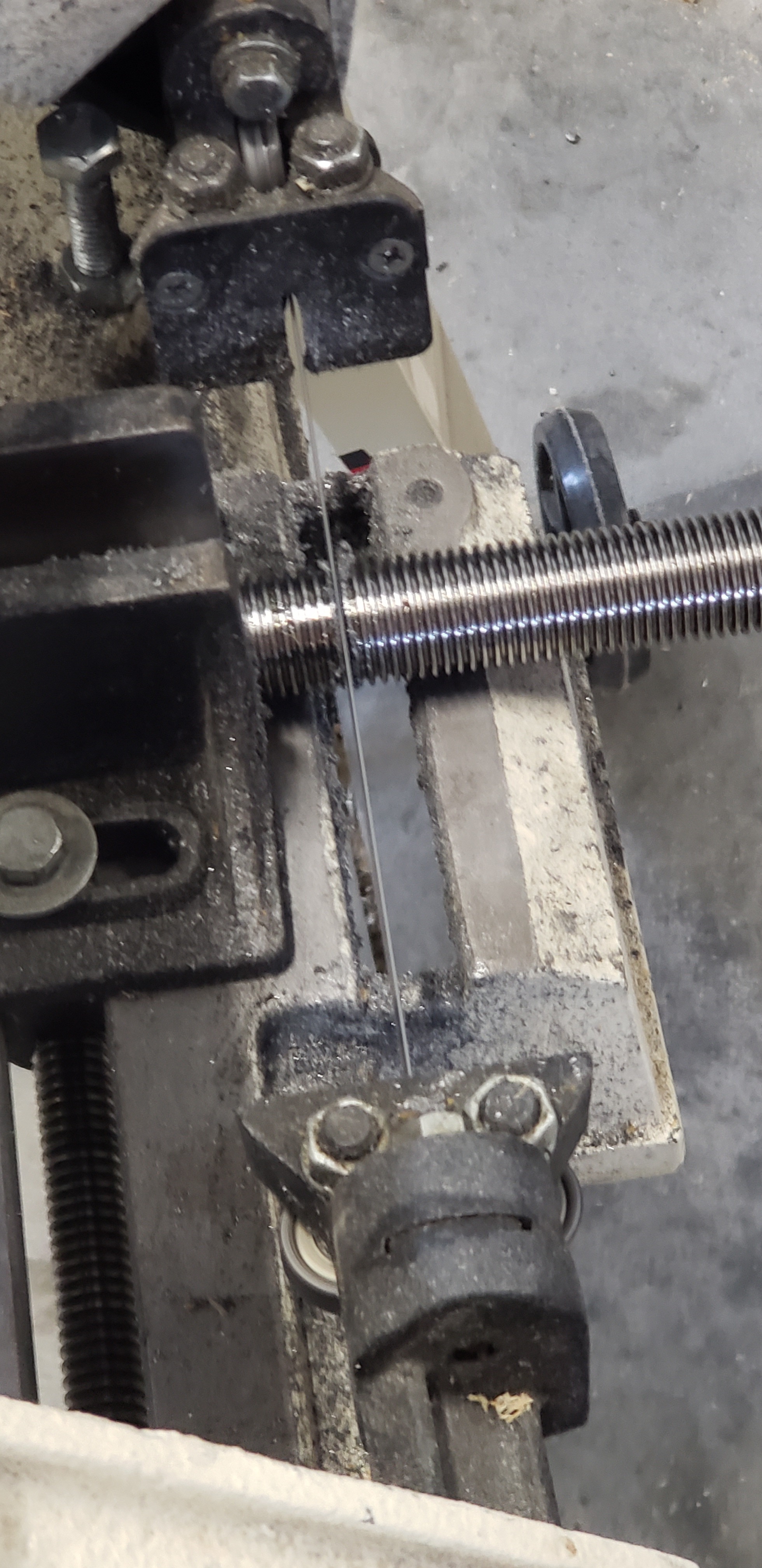
Cut a large section of acme screw into two 2.5" sticks for use as lift system power screw.
Machining Nut Threads
Take two nuts and drill the threads out of them and prepare them to be welded to the acme screw as a point for power transfer.
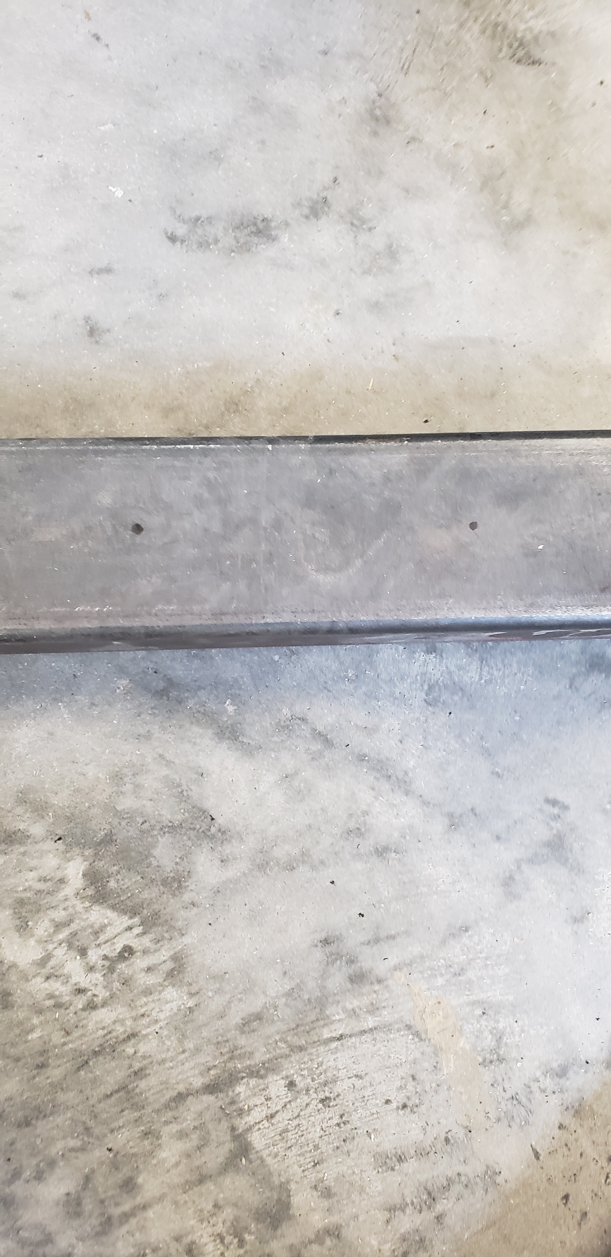
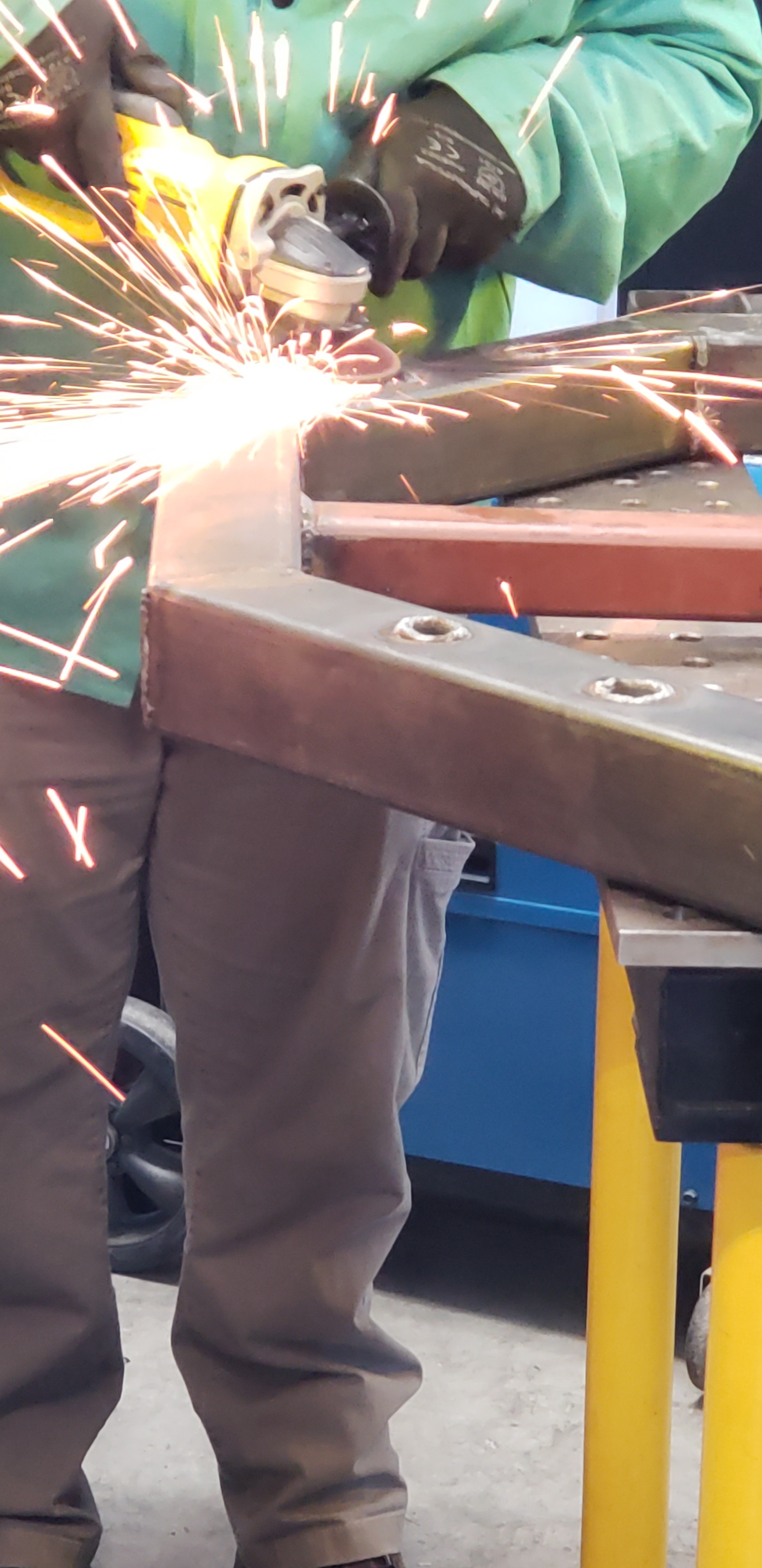
Grinding Plate for the Caster Wheels
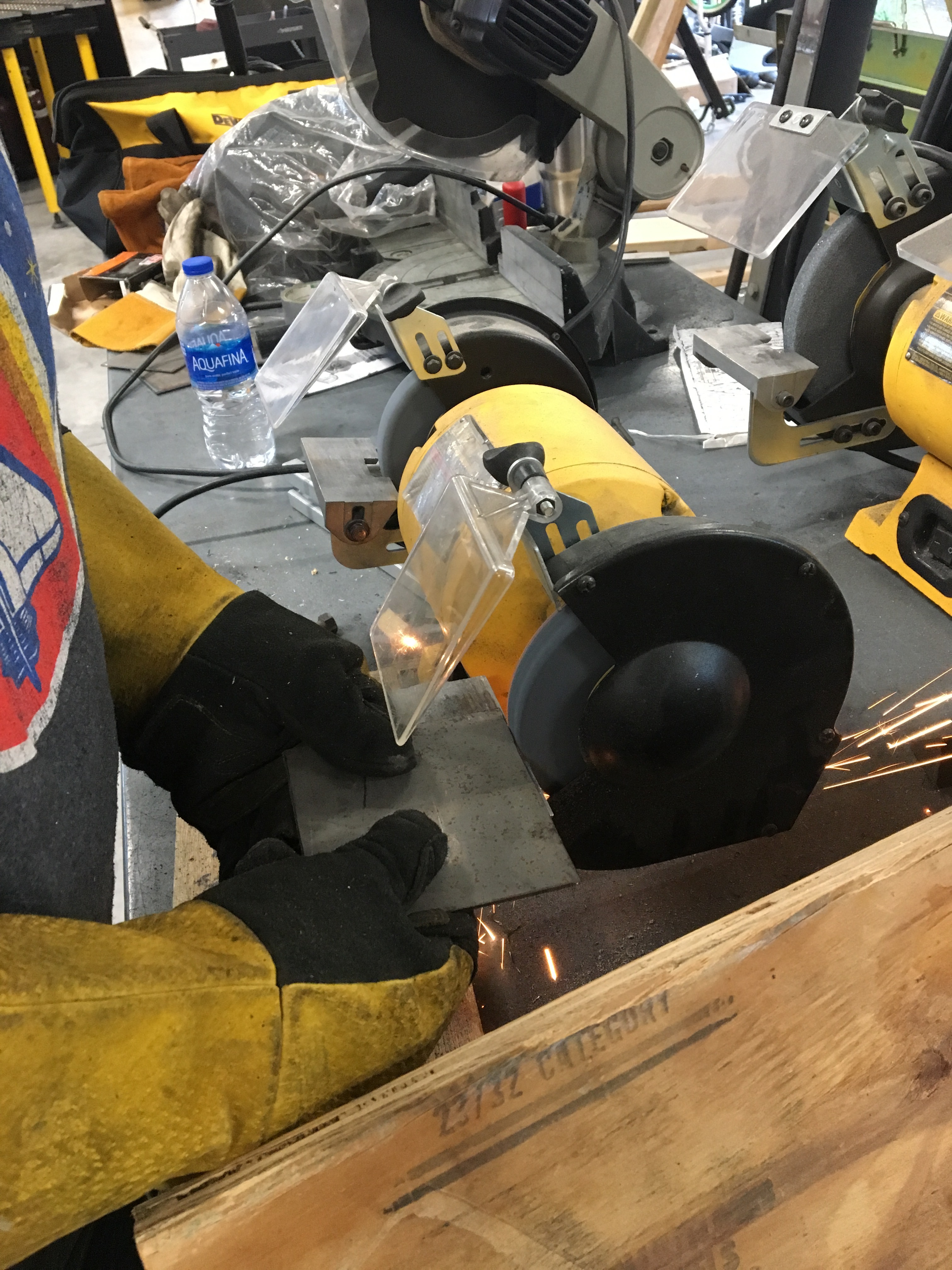
Cut sections of weldable square steel with the same dimensions as the castor wheels' base. Grind the edge with a bench grinder and prepare the edges to be welded to the leg of the Kuka stand.
Template to Mark Holes for the Bungs
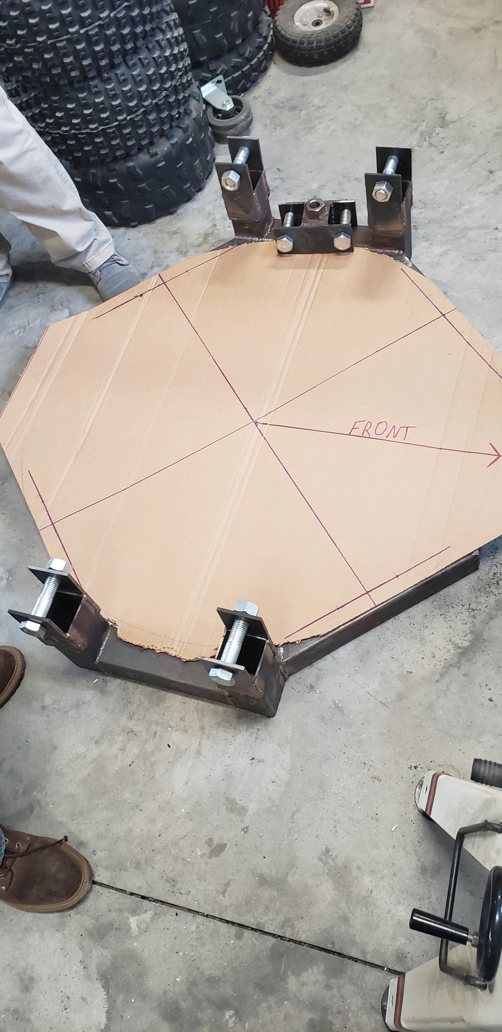
Make a cardboard templet of the Kuka robot to be able to measure where we will drill the holes that will be used to secure the Kuka robot on the stand.
Marking Holes Using Template
Mark the holes in a visible color to mark future drill sites.
Center Punching Marked Points
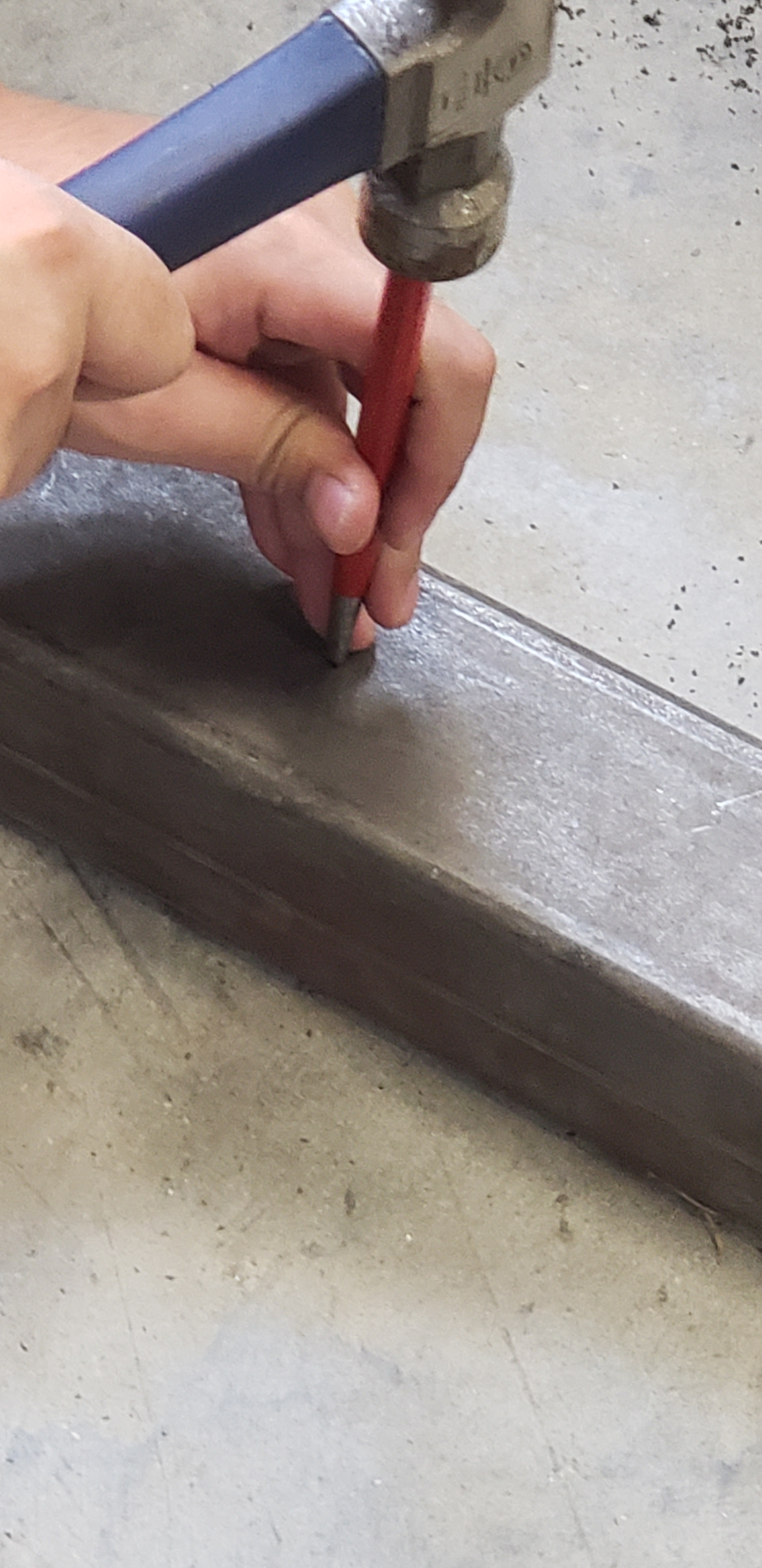
Center punch the 8 marked holes to make drilling the hole easier.
Drilling Holes on Octagon
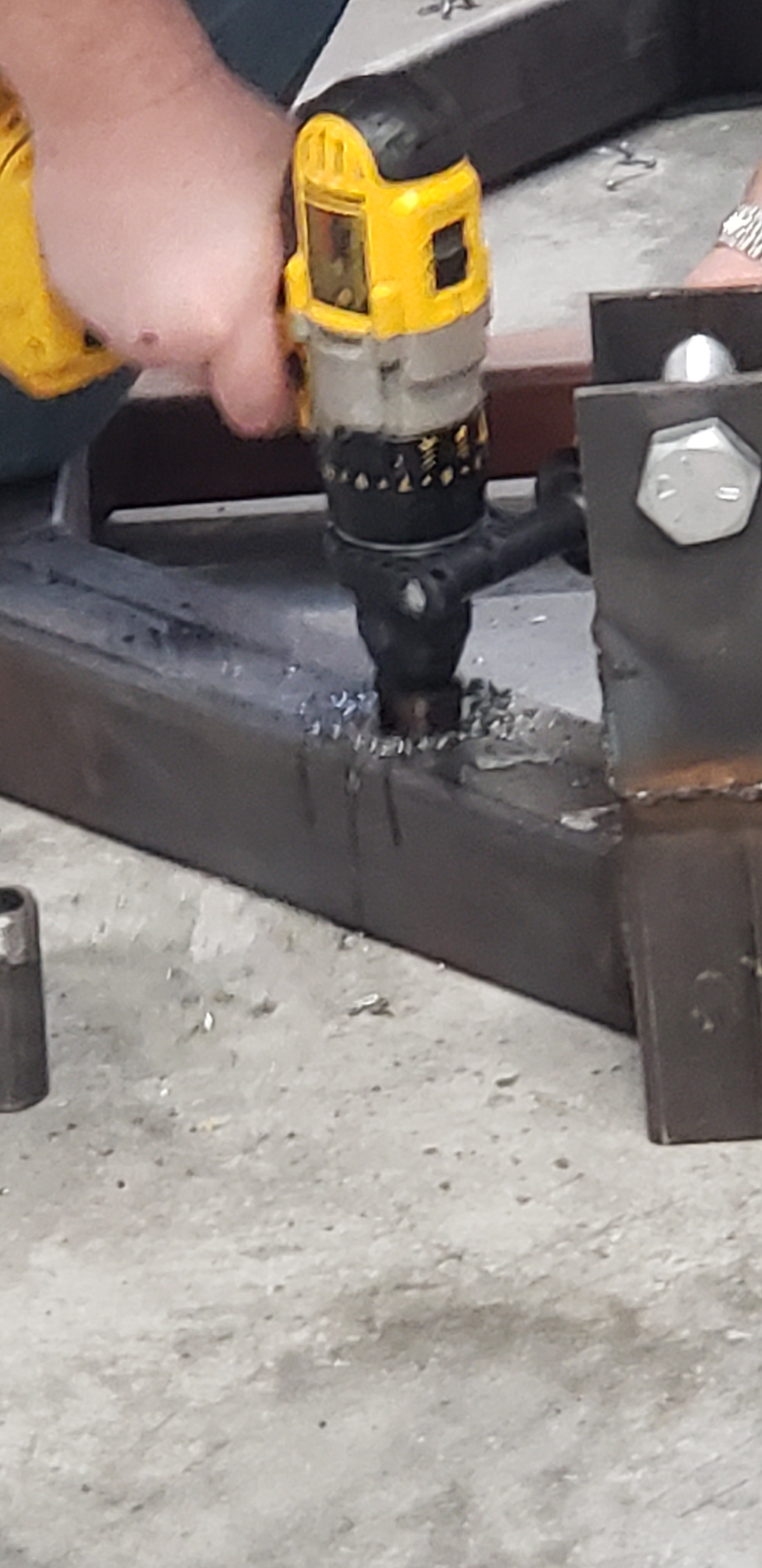
Drill out 1" diameter hole with loose tolerancing to be able to snuggly fit tapped bungs into and welded into place.
Fill in the Bung Placement Hole With Bung
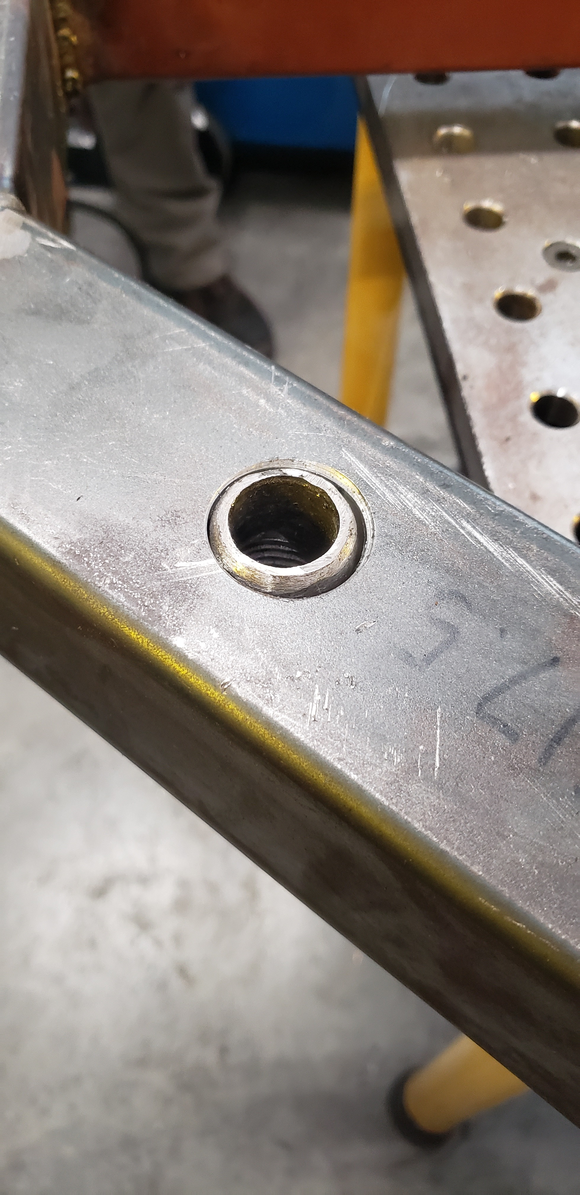
This step will align with the bungs in the same dimensions as the Kuka's mounting holes.
Weld Bungs in Place
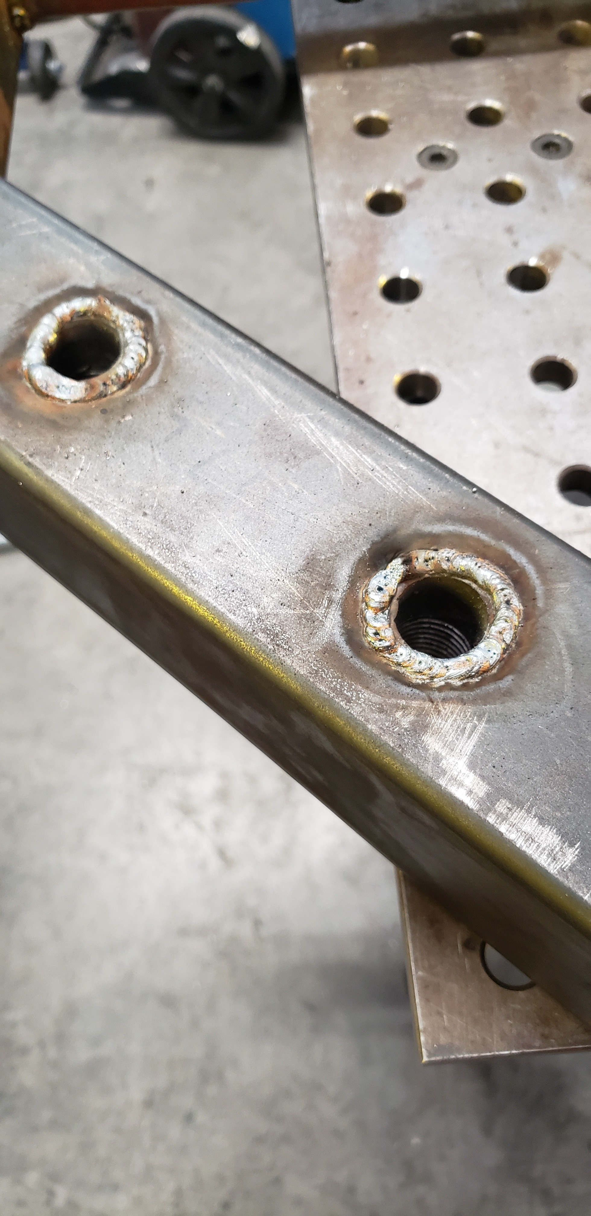
Secure the bungs in place and weld the bungs to the frame filling any gaps with welds.
Clean Up Your Bung Welds
Make the bung holes flush with the rest of the Kuka frame by grinding down any protrusions.
Assemble All Pieces to Test Fit.
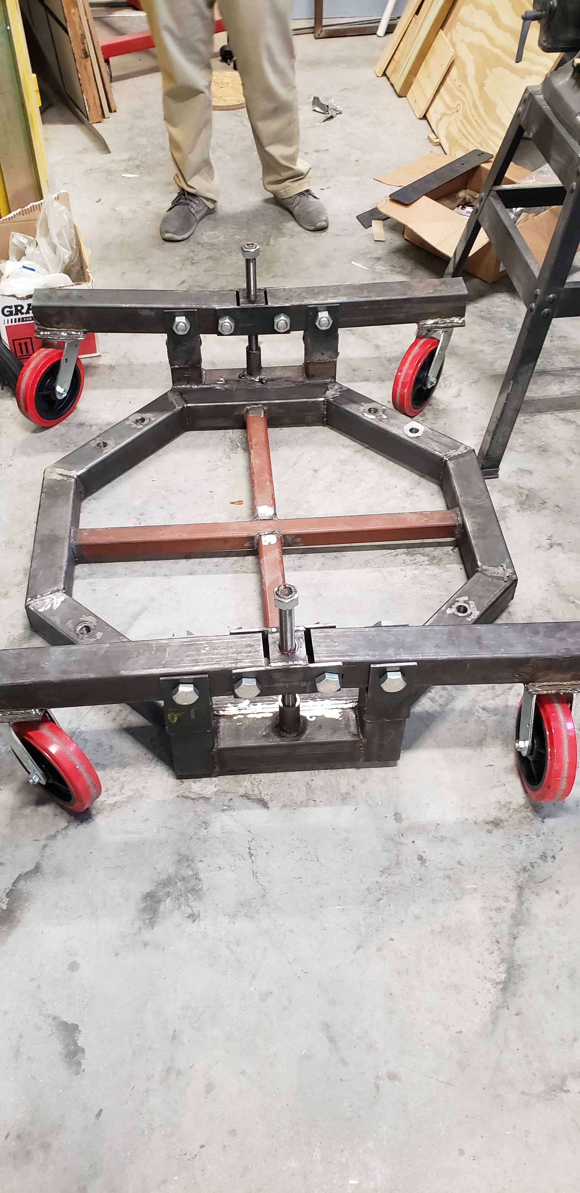
Make sure grease goes where grease needs to go so no coupling system is too tight. The majority of the grease should go into tube that holds the acme screw as well as the coupler. If needed, put the grease in the bearing of the caster wheels.
Test Load
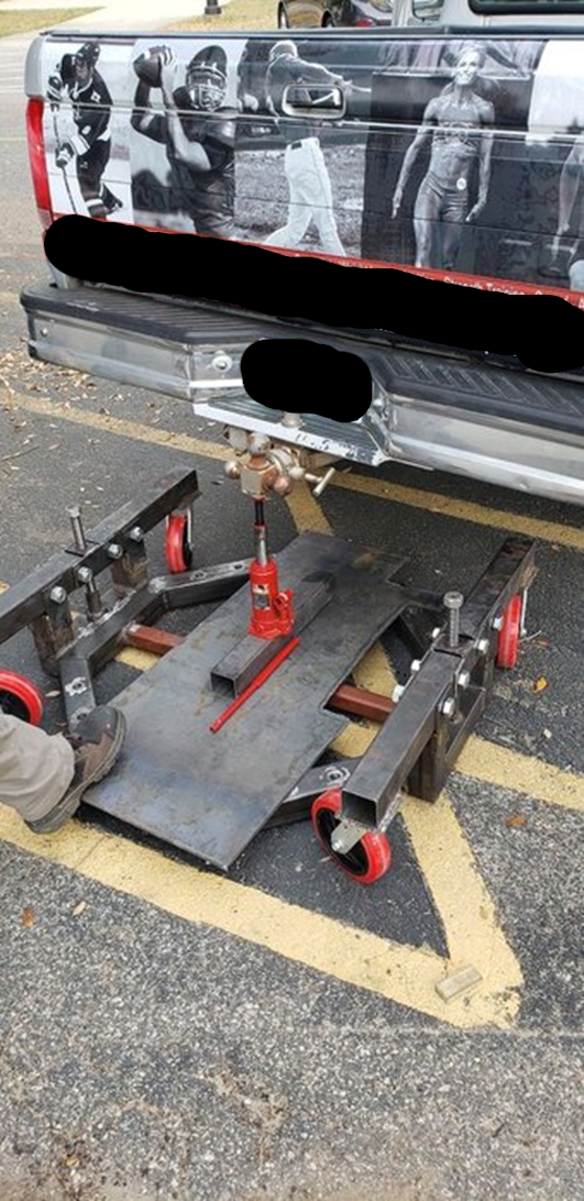
To ensure the quality of the build and connecting points the mobile stand was put to a rough estimated load test of around 2500 pounds.