How to Make a Mini Playhouse in SolidWorks.
by bmsoto in Design > Digital Graphics
143 Views, 0 Favorites, 0 Comments
How to Make a Mini Playhouse in SolidWorks.

Target Audience: High School/Beginner at SolidWorks
In this tutorial, you will create a mini playhouse. By creating the model, you will learn how to use tools such as:
- Sketch
- Smart Dimension
- Extrude Boss/Base
- Extrude Cut
- Mirror
- Offset
- Appearances
- and more!
This tutorial will help you achieve the following standards:
- Integration of Knowledge, Technologies, and Practices
- Design in Technology and Engineering Education
* This model can be created in a variety of different ways. This is just one way to complete this model. Feel free to use steps that make more sense to you if you already have experience with SolidWorks.
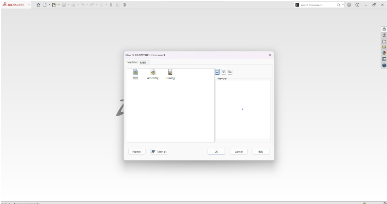
Open a part file in SolidWorks.
We will be working in IPS (inch, pound, and second). (If you are not in IPS, select the “Tools” tab from the drop-down menu, or go to the bottom right corner and click on the upward arrow to quickly switch units or select edit document units.)
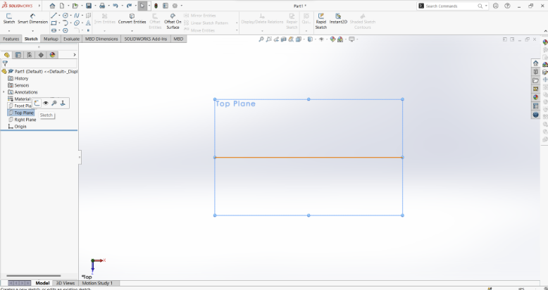
Start your sketch on the top plane.
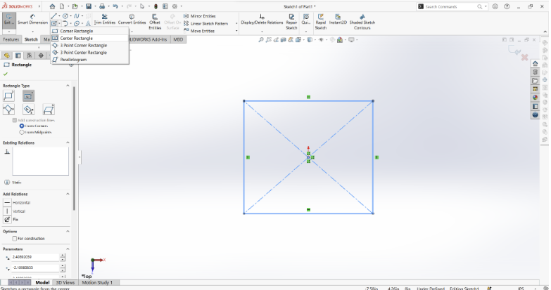
Draw a square from the origin using a center rectangle tool. There is no need to make a perfect square. We will fix that in the next step.
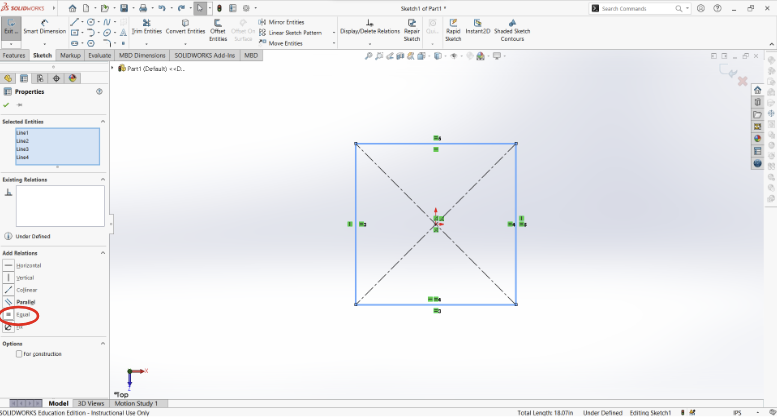
While holding down the shift key, click all four sides of the square and make them equal.
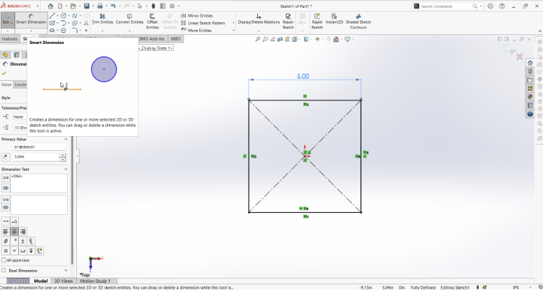
Add dimension:
- Click “Smart Dimension”.
- Click one side of the square and drag the dimension out.
- Change the value to 5 in.
You can also change the value by going to the side panel and changing the value under “Primary Value”.
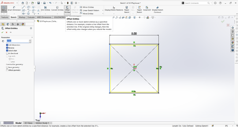
Offset entities:
- Click “Offset Entities”
- Make sure you enter the following under “Parameters”
- 0.10 in
- Check “Add dimensions”
- Check “Reverse”
- Check “Select chain”
- Click the check mark
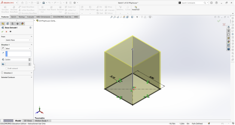
Extrude Boss/Base:
- Go to the “Features” tab
- Click “Extrude Boss/Base”.
- Set the extrusion to 6 in. (Make sure the direction is “Blind”)
- Click the check mark.
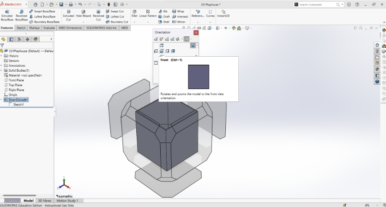
Go to the front view by clicking the space bar and choosing “Front” or use the Ctrl+1 shortcut.
Tip: If you accidentally change your view, click the space bar, and you can choose what view to go back to.
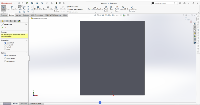
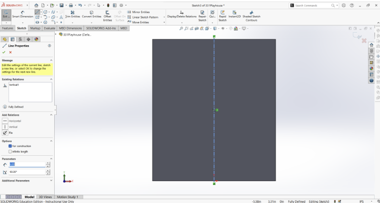
Sketch a construction line:
- Go back to the “Sketch” tab and click "Sketch".
- Click on the front face of the shape.
- Click the “Line” tool.
- Make sure “For construction” is checked.
- Click the origin and drag a straight line to the top of the shape by following a dotted blue line and clicking the point that will pop up.
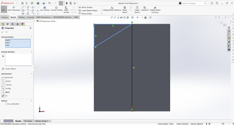
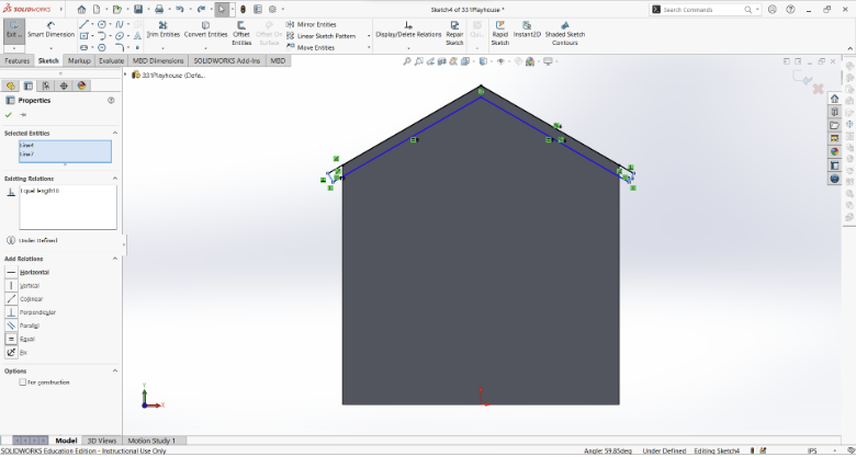
Using the “Line” tool, create a triangle in one of the top corners. Reference the photo below (Do not use construction lines).
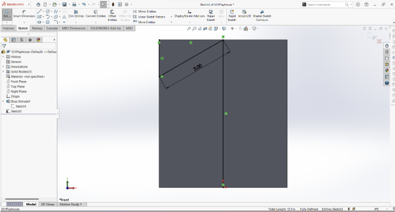
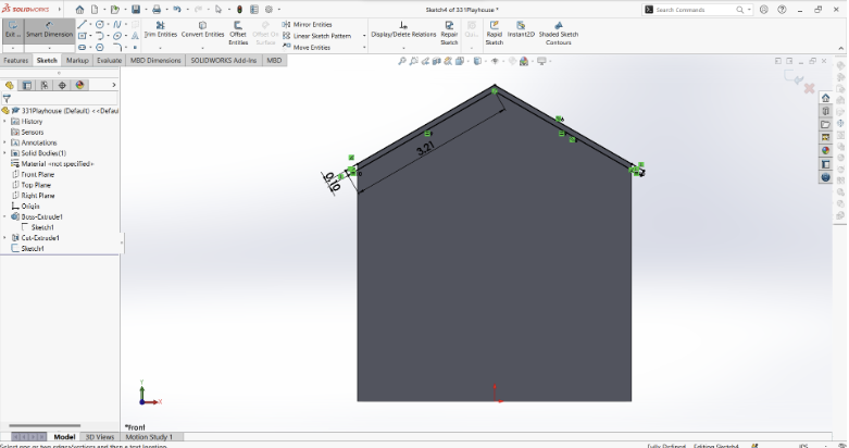
Dimension the hypotenuse of the triangle to be 3.
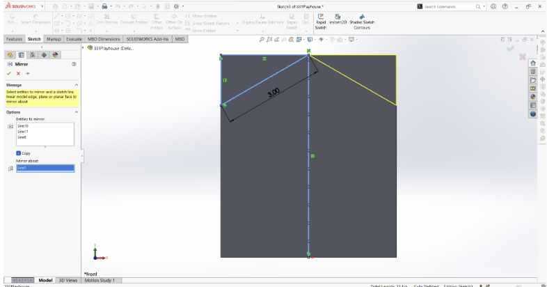
- Click “Mirror Identities”.
- Click the three sides of the triangle.
- Click the box under “Mirror About”.
- Click the center construction line.
- Click the check mark.
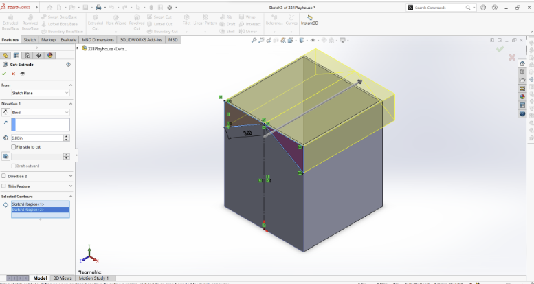
Extrude cut:
- Go to the “Features” tab
- Click “Extrude Cut”.
- Click the two triangle shapes.
- Make sure the cut is going all the way through.
- Click the check mark.
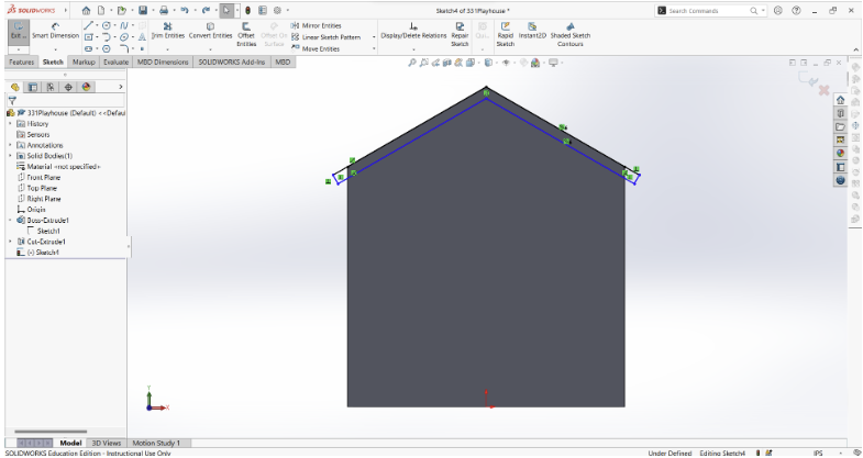
Make the roof:
- Make a sketch on the front of the shape.
- Make the shape with the guides that will show up when you are creating the sketch. You may need to make a sketch that matches the top of the house and add lines that extend outward a bit on each side.
- Using the “Line” tool, create the shape below on the top edge of the shape.
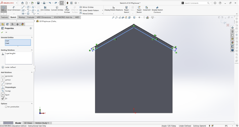
Add relations:
- While pressing shift, click the bottom two lines, and make them equal.
- While pressing shift, click the two lines on the side and make them equal.
Add dimensions:
- Make one of the lines on the side 0.1 in.
- Make one of the lines at the bottom the same as it is. Just extend the dimension line.
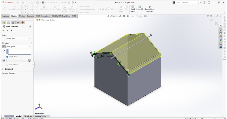
Extrude Boss/Base:
- Go to the “Features” tab
- Click “Extrude Boss/Base”.
- Make sure Direction is “Through All”
- If the extrusion is facing the wrong direction, click the box with the arrows beside “Through All”.
- Click the check mark.
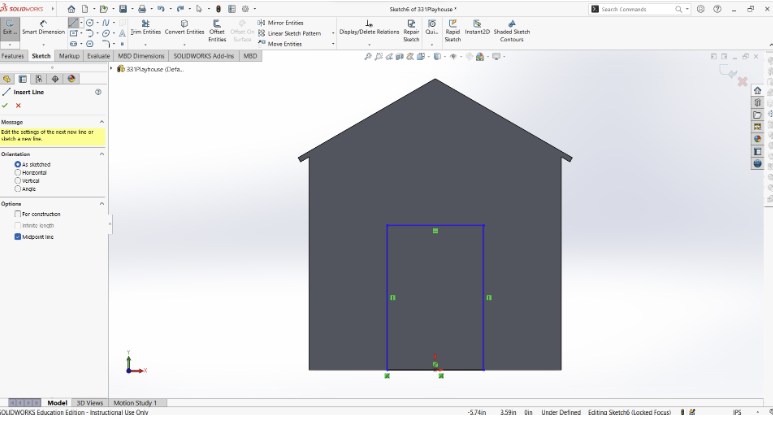
Sketch a door:
- Create a sketch on the front of the house.
- Click the “Line” tool and choose “Midpoint”.
- Click the origin and move to one side. (This should go to both sides)
- Create the rest of the rectangle.
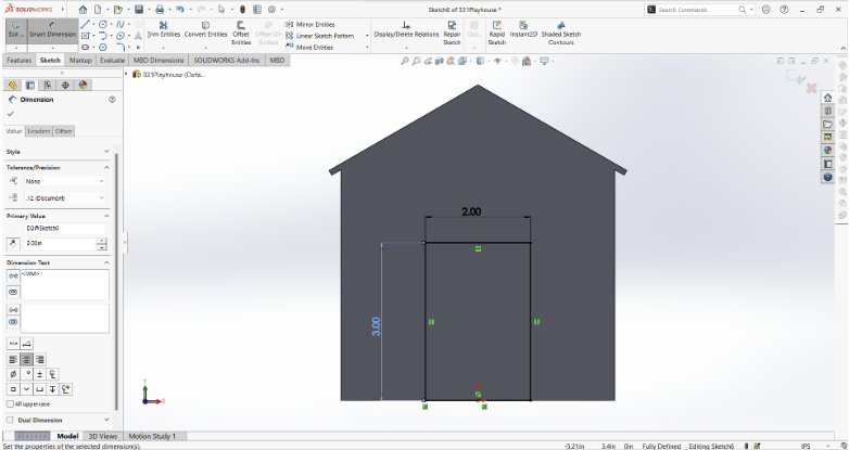
Define door dimensions:
- Make the top 2 in.
- Make the side 3 in.
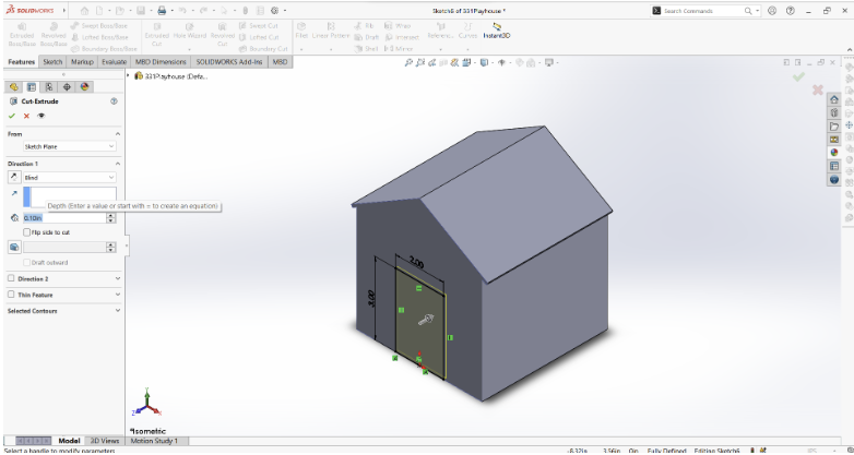
Extrude Cut door:
- Go to the “Features” tab
- Click “Extrude Cut”.
- Set the direction to “Blind”
- Set the cut depth to 0.1 in.
- Click the check mark.
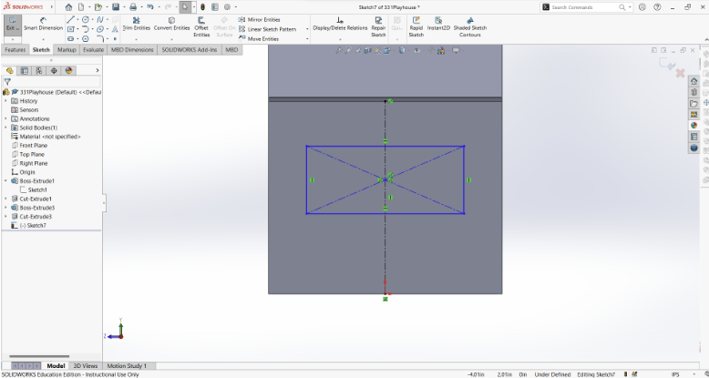
Sketch windows:
- Create a sketch on the side of the house.
- Create a vertical “Center Line”.
- Using the “Center Rectangle” tool, add a rectangle onto the center line.
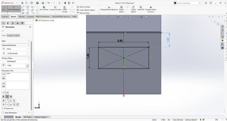
Define door dimensions:
- Make the rectangle 3.5 in wide and 1.5 in tall.
- Click the bottom of the roof overhang and the top of the rectangle. Drag the dimension to the side and make it 1 in.
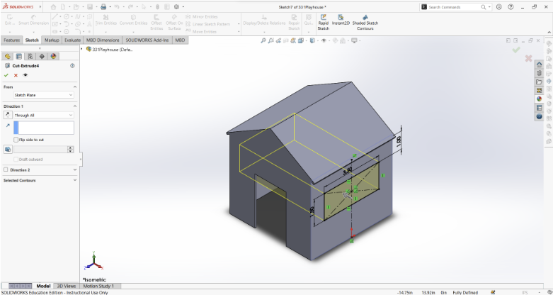
Extrude Cut windows:
- Go to the “Features” tab
- Click “Extrude Cut”.
- Set the direction to “Through All”
- Click the check mark.
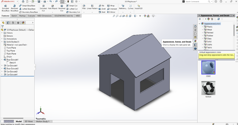
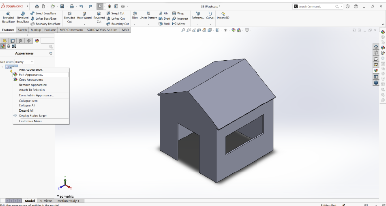
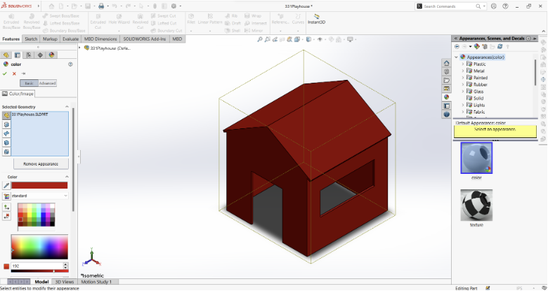
Change the color:
- Go to the “Appearances, Scenes, and Decals” tab on the right of the screen.
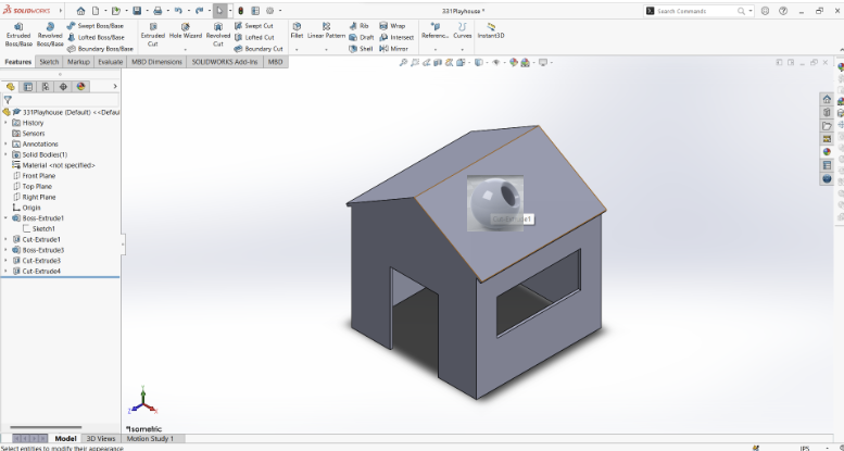
- Drag and drop “color” onto the playhouse.
- Click on the part.
- Go to the display manager on the left of the screen, right-click “color”, and click “Edit Appearances”.
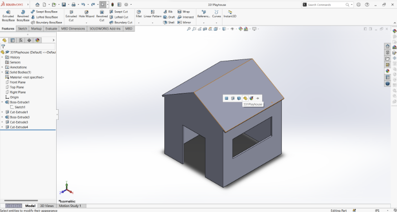
- Pick the color of your choosing.
- Click the check mark.
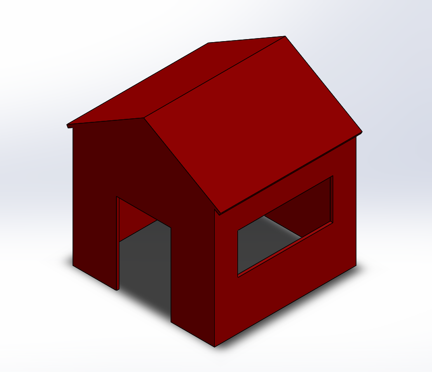
You have completed your mini playhouse!