How to Make a Mini Compressed Air Turbine
by fozzy13 in Workshop > Science
270102 Views, 764 Favorites, 0 Comments
How to Make a Mini Compressed Air Turbine
In case you didn't know this yet, compressed air is pretty awesome. With simple mechanical systems - pumps - energy can be stored and used for an infinite amount of applications. What I like about compressed air is how simple and accessible it is. Anyone with a bike pump can start moving air to greater pressures. Soda-pop bottles can be turned into air tanks, and by looking a little online and on Instructables, you'll find people who've used compressed air to do everything from shooting water balloons to powering a bicycle.
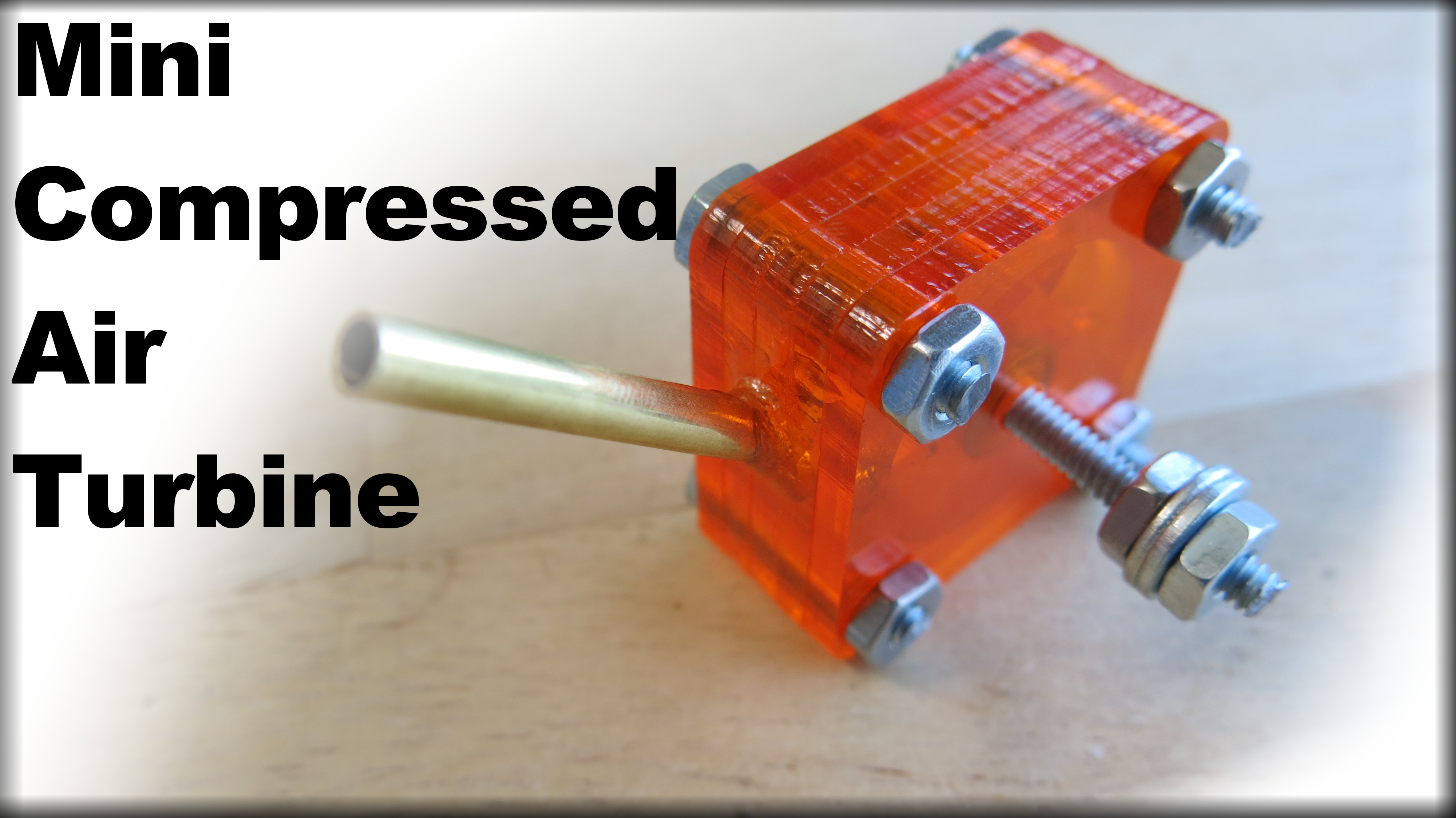
In this Instructable, I will show how I made a miniature compressed air turbine.
-
8/16/13: Thank you for the feature!
8/16/13: I'm just shy of 9000 views in barely 12 hours! Thanks everyone!
In this Instructable, I will show how I made a miniature compressed air turbine.
-
8/16/13: Thank you for the feature!
8/16/13: I'm just shy of 9000 views in barely 12 hours! Thanks everyone!
Video!
"A Compressed What-!?": Theory of Operation
Let's start from the very beginning, shall we?
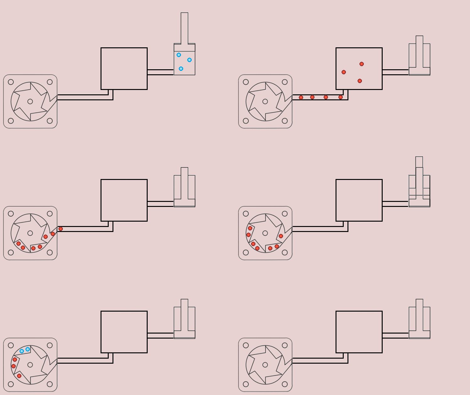
All matter is composed of atoms. In solids, these atoms are packed very tightly together, which is why they are -erm, solid. The atoms are forced together and don't flow around much. In a gas however, the atoms are able to move around freely. So freely in fact, that gases don't have a "form", and instead take the form of whatever container they are in. Gases can be held at different pressures. The pressure of a gas is a reflection of how many atoms are forced into a given space. By using a pump, one can force more gas atoms into a space, increasing the pressure. If you have a container filled with a gas that has had extra atoms pumped into it, and you open the container, the high pressure atoms will move to the area with the low pressure atoms until the overall pressure is equal. The concept that a high pressure gas will move to an area of lower pressure is the concept that will drive our compressed air turbine.
The compressed gas will move through the turbine to the area outside the turbine. As it moves through it, the air will push the fins, and cause the turbine to rotate. The gases will move toward the center of the turbine, where they exit the exhaust hole.
I made a really fun .gif showing the air molecules being compressed, and then moving the turbine! I hope it helps!
Tools/Materials
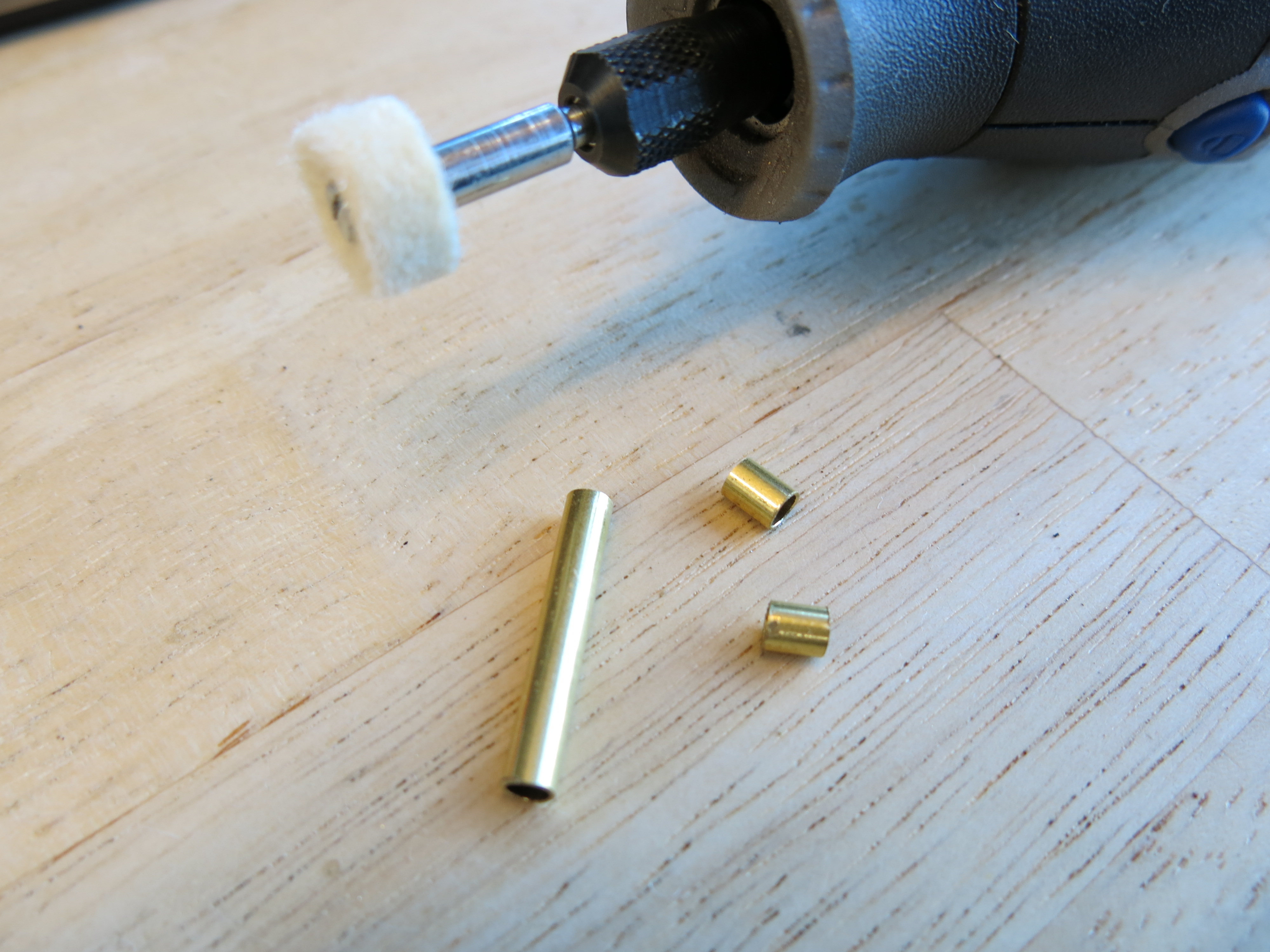
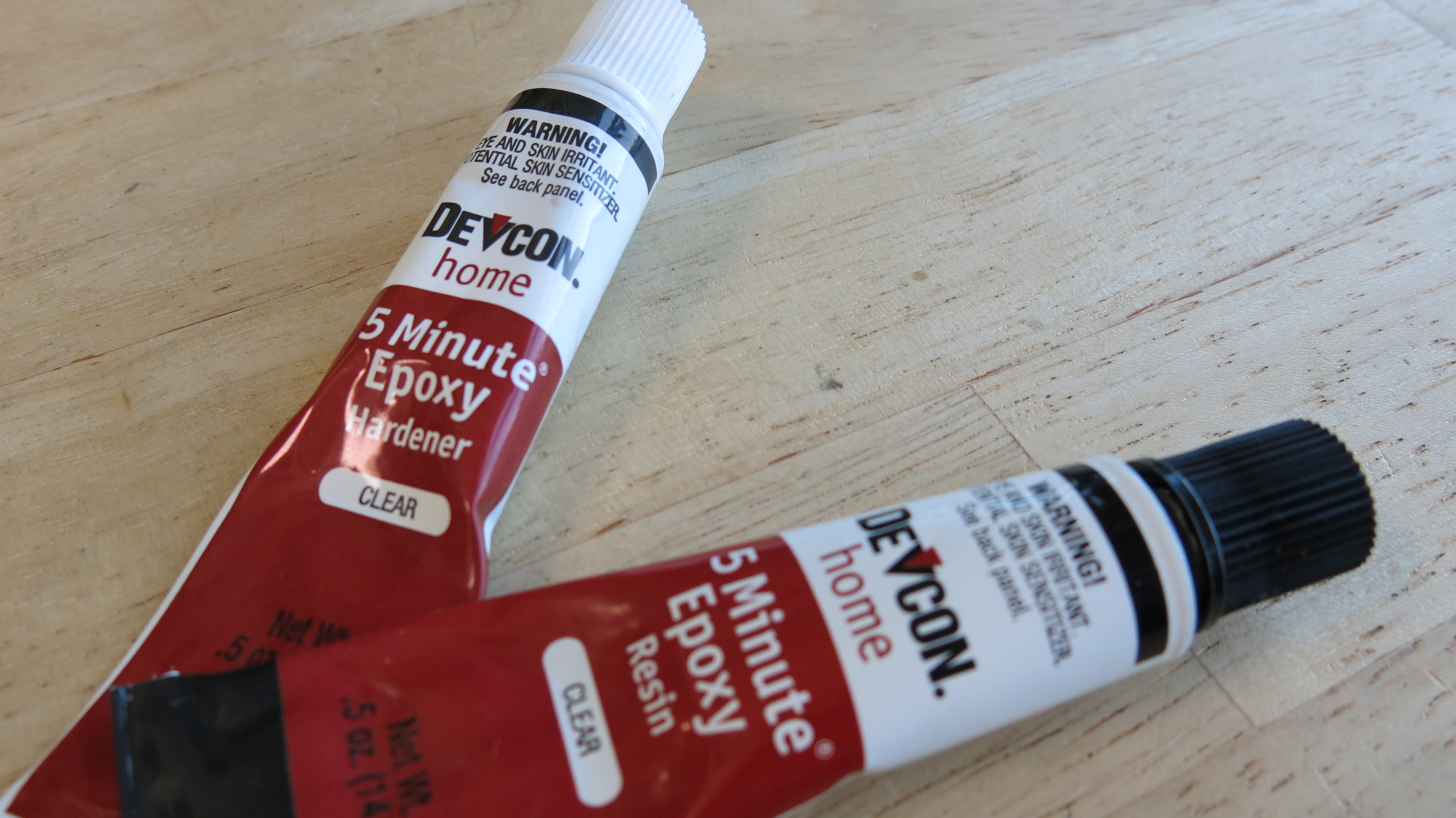
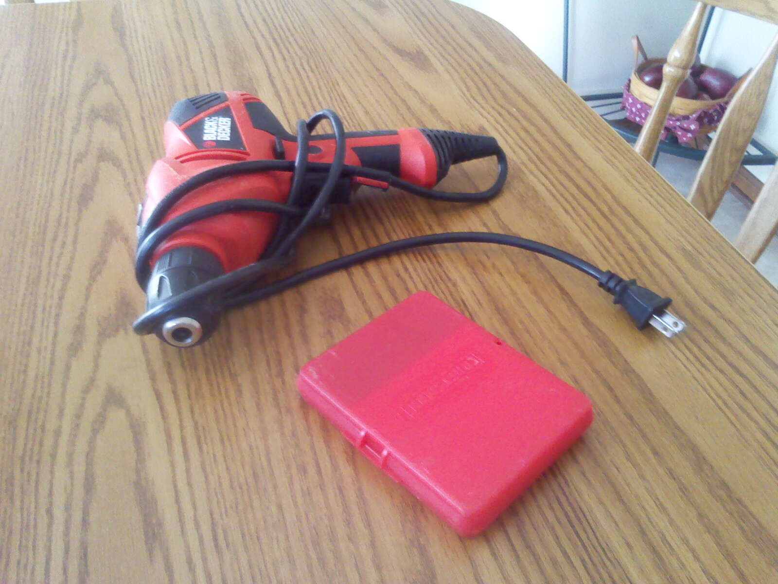
Very few tools and materials were used to make this turbine. Here they are!
Tools:
1. Inkscape is an open-source vector graphics creator. If you've heard of Adobe Illustrator, this is like a free version of that program. I'm using it because it's free and available, but feel free to use your vector-graphics editor of choice. Or you can get Inkscape for free here.
Tools:
- Epilog laser cutter
- Inkscape1
- Dremel rotary tool
- Hand drill
- 1/8" Acrylic sheet - I used a cool orange one I found in the shop.
- 6-32 threaded rod. It's roughly 1/16" diameter.
- 6-32 washers and nuts.
- 1/8" diameter brass tube - this is from K&S metals and I got it at the local hardware store. Awesome tubes to work with.
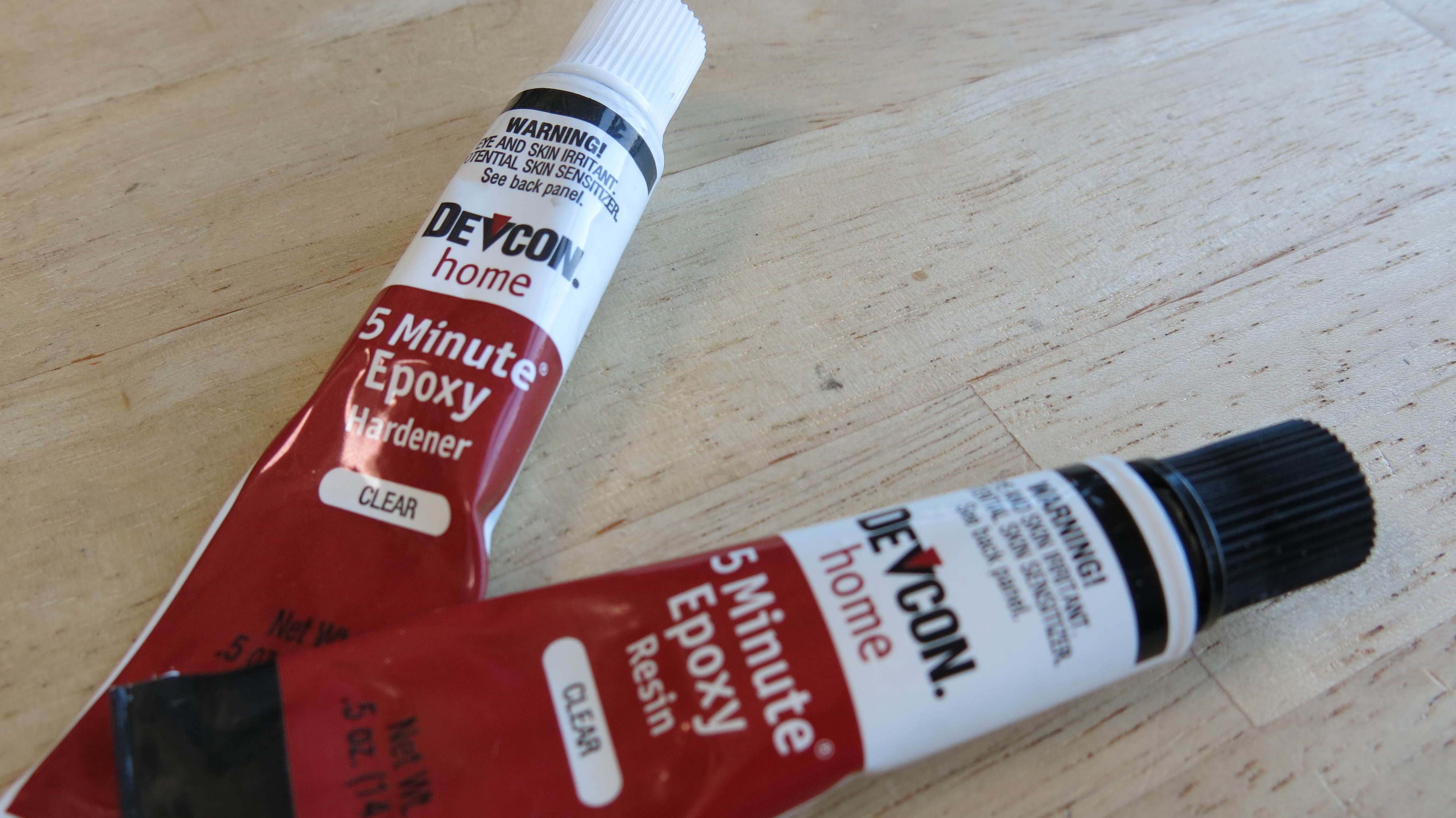
- 5 minute clear epoxy
1. Inkscape is an open-source vector graphics creator. If you've heard of Adobe Illustrator, this is like a free version of that program. I'm using it because it's free and available, but feel free to use your vector-graphics editor of choice. Or you can get Inkscape for free here.
Design - Turbine
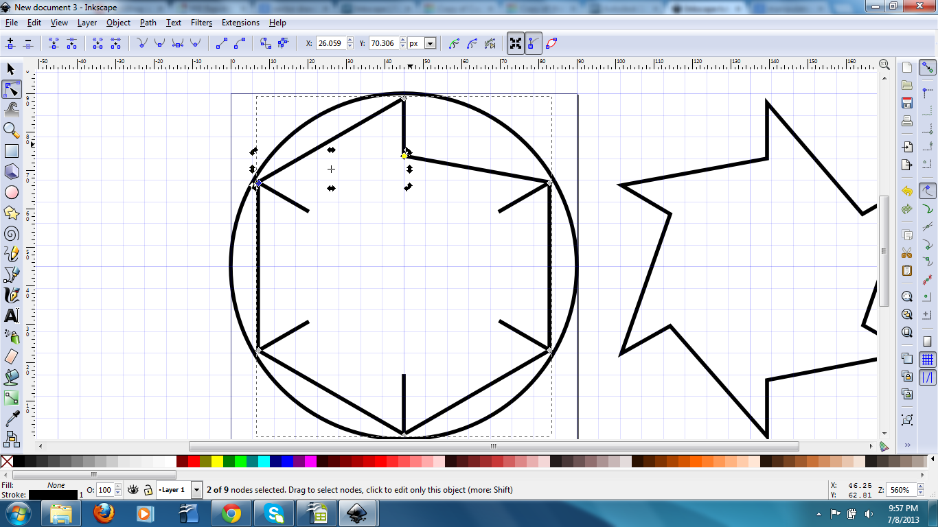
I designed my compressed air turbine in Inkscape. Everything was kind of made up as I went along since I'd never used the program, and had no purpose in mind for the final product.
Not familiar with Inkscape? I highly recommend reading through this first. IT helped me find my way around and will help you follow the instructions below better.
To draw the center turbine, I did the following in Inkscape:
Not familiar with Inkscape? I highly recommend reading through this first. IT helped me find my way around and will help you follow the instructions below better.
To draw the center turbine, I did the following in Inkscape:
- Make a new image. Click "FIle>Document Properties". Set default unit to "inches"; "width" and "height" to 1; and grid to 1/16" or .0625.
- Draw a circle. Click the center of the grid, and hold down "Shift" and "Ctrl". Drag the cursor to a corner, where it will snap to the grid to form your perfect, 1" diameter circle.
- Draw a hexagon. I wanted my turbine to have six fins. Use the same technique as that used for the circle in the previous step, but stop when the corners of the hexagon contact the edge of the circle. It may help to go into the Document Properties and turn off grid-snapping for this.
- Convert to "nodes". Select the hexagon and press "Shift+Ctrl+C". This will change the object to a path, which will let us manipulate it more easily.
- On the right hand side, there is a toolbar, with a button to allow "snap to cusp nodes". I had this feature turned on for the majority of my node-manipulation work.
- Draw guidelines. I draw a line segment from the top node of my hexagon down. This segment was copied, pasted, and rotated 60-degrees multiple times, and placed on all the corners of the hexagon.
- Node-manipulation. Select the hexagon, and a node. Use the "break-path" function to break the path at that node. Select a node at the broken point and drag it to the bottom of the line segment. This is where it should "snap to cusp node". Repeat this for each corner. Select each corner, and "join selected nodes" to make one solid path.
Design - Housing
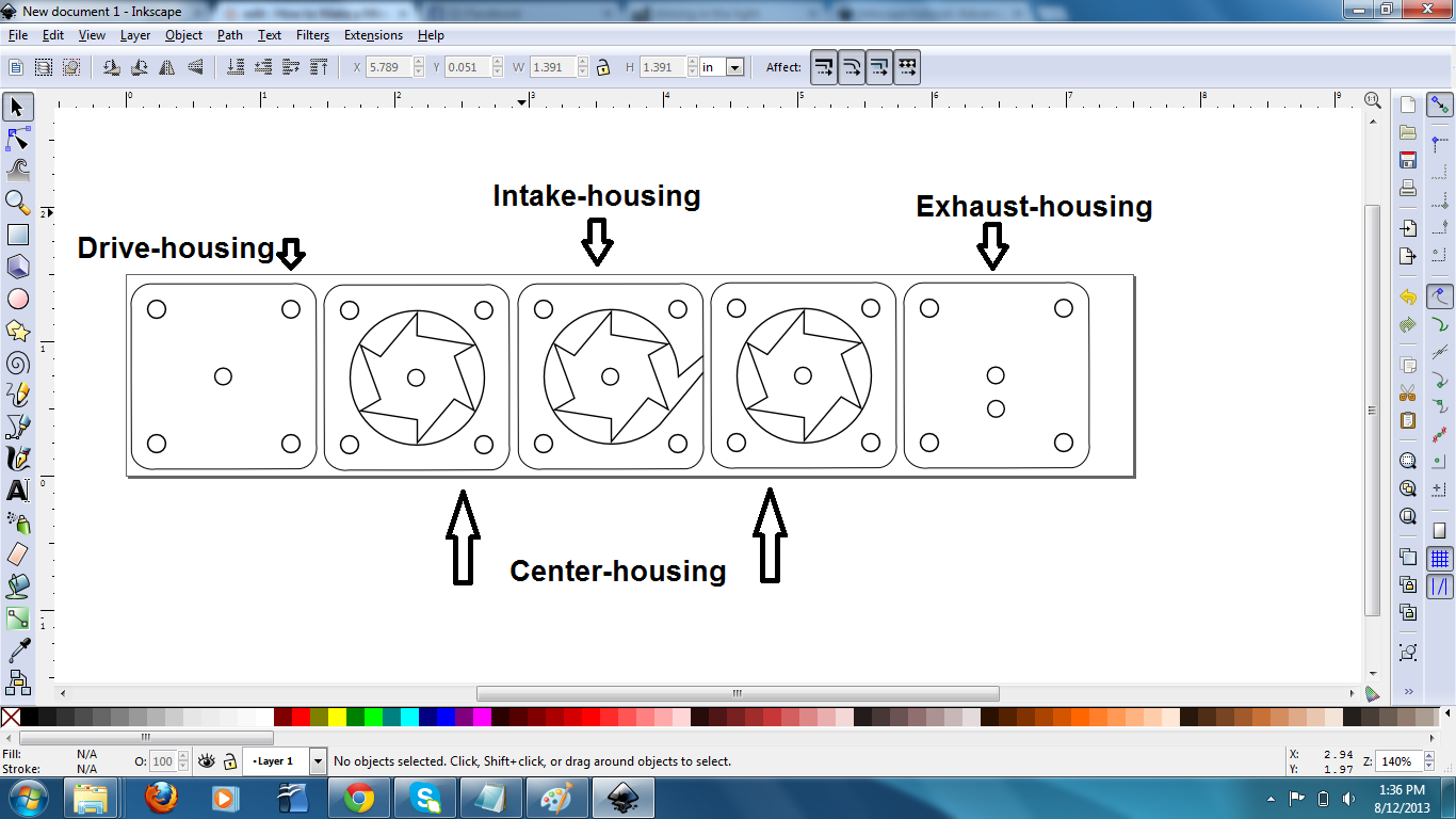
Now that the center, and only moving part is designed, we'll need a housing to make everything work!
The housing itself is composed of layers. These layers bolt together to make the housing one piece. I attached .pdf's of each layer! The .svg's were unhappy when I tried to upload them..
Center-housing:
- where the turbine will spin inside of.
- where the air will flow into the turbine.
- where the shaft will leave the housing, and be able to do work.
- where air will exit the turbine, and the shaft will be supported.
The housing itself is composed of layers. These layers bolt together to make the housing one piece. I attached .pdf's of each layer! The .svg's were unhappy when I tried to upload them..
Center-housing:
- where the turbine will spin inside of.
- Make a new document. Set default units to "inches"; "width" to 1.44; "height" to 1.44; grid to 1/16", or 0.0625. This turbine is tiny!
- Copy-paste the turbine we drew in the last step into the center of the new document.
- Draw holes. These will be used for assembly later. I used the same technique (Shift+Ctrl+drag) as in the last step to draw perfect, 1/16" circles, and positioned them with the help of the grid around the turbine. These ended up being too small and had to be drilled slightly for ease of use, so keep in mind that you may want to make them larger.
- where the air will flow into the turbine.
- Begin with the Center-housing we drew above.
- Select the circle in the center of the turbine. Convert to path. Break path at selected nodes. I selected the one on the right-hand side of the circle.
- Use the "Draw Bezier curves and straight lines" tool, along with the "snap to nodes" function to draw lines from the broken circle to the side of the housing.
- Remember to save this as a different file, so you don't overwrite and lose the Center-housing.
- where the shaft will leave the housing, and be able to do work.
- Start with the Center-housing we drew above.
- Select and delete the turbine and circle, leaving just the center circle in place.
- Save as a different file.
- where air will exit the turbine, and the shaft will be supported.
- Start with the Drive-housing from above.
- Copy-paste the center hole, and move it down slightly.
Assembly!
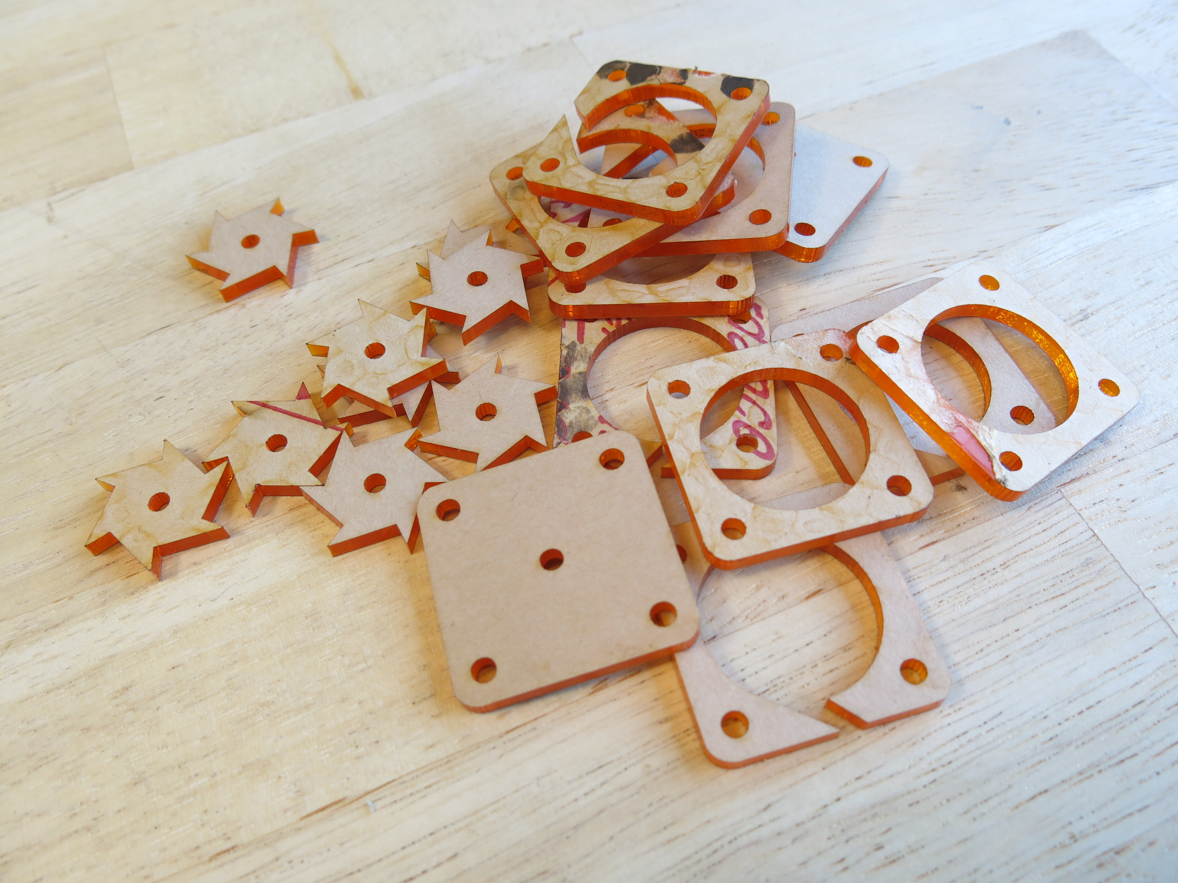
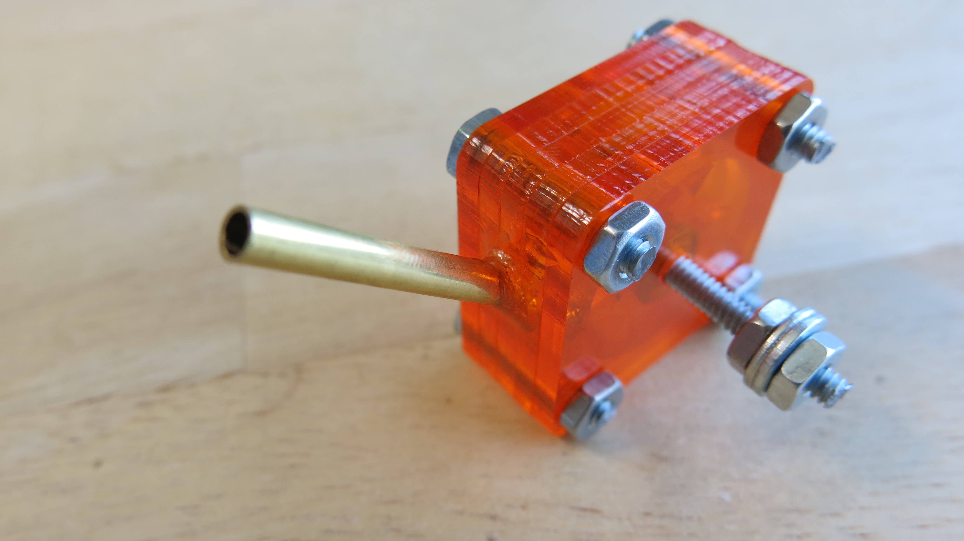
Designs have been made, and you've used a laser cutter to cut them out. Setup will depend on what type of laser cutter you have available. For my project each file was exported as a .pdf, and then imported and arranged into CorelDraw, because it's a program that plays nicely with the laser cutters. The pieces were cut out of transparent orange acrylic. The protective paper over the parts needs to be peeled off.
Approximately 1.5" segments of 6-32 threaded rod were cut using a Dremel rotary tool with a cutoff wheel. These were put into the holes on the corners, and held in place with equivalent nuts. The holes on the corners were made slightly wider with a hand drill for ease of assembly.
The shaft was made using a 2" section of the same 6-32 threaded rod, and two of the turbine pieces were threaded on to the center. Two small washers were used to close the space in between the turbine pieces and the sides of the housing. The center holes were both made slightly wider with a hand drill to allow for the threaded rod to move more smoothly.
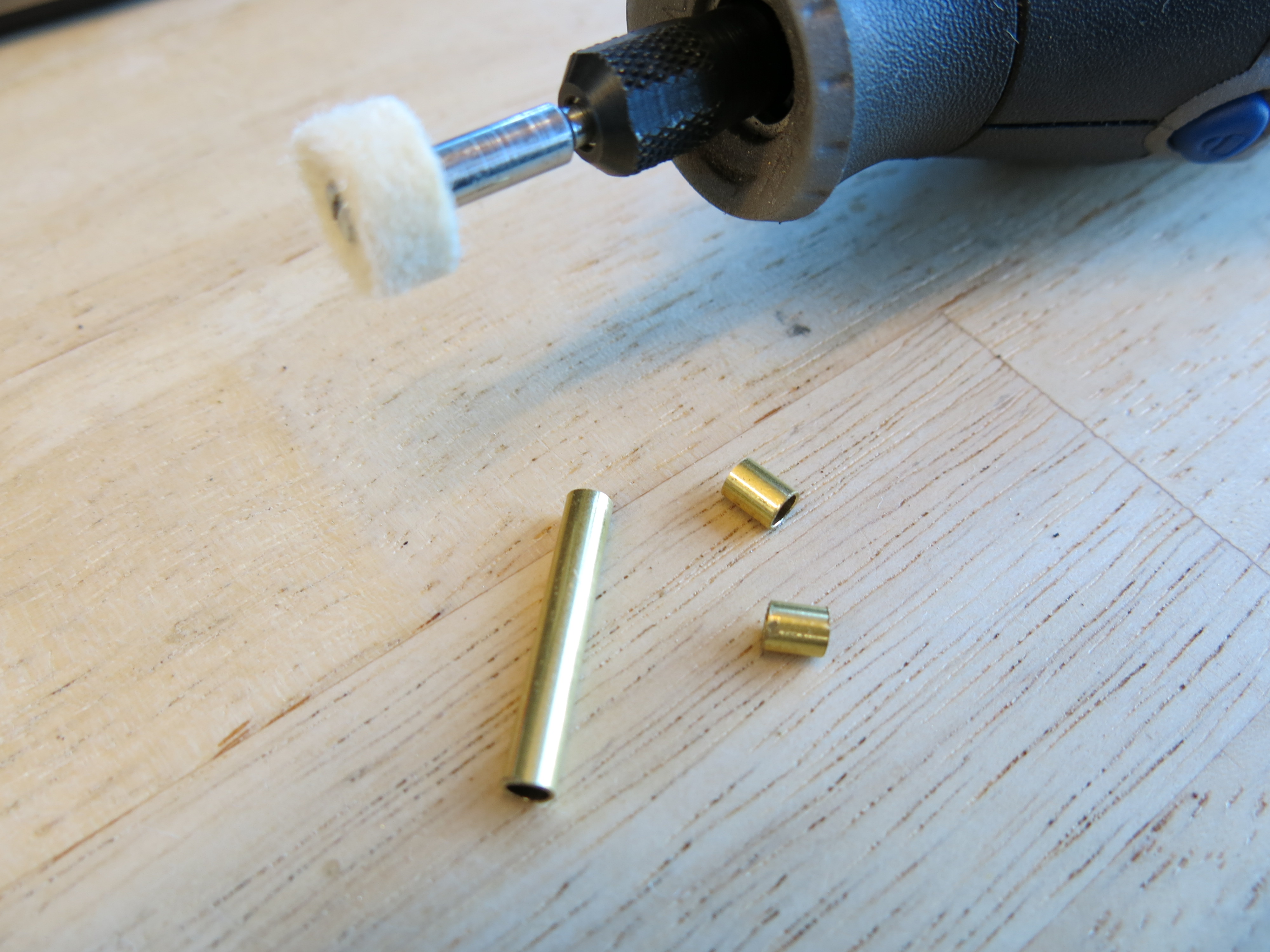
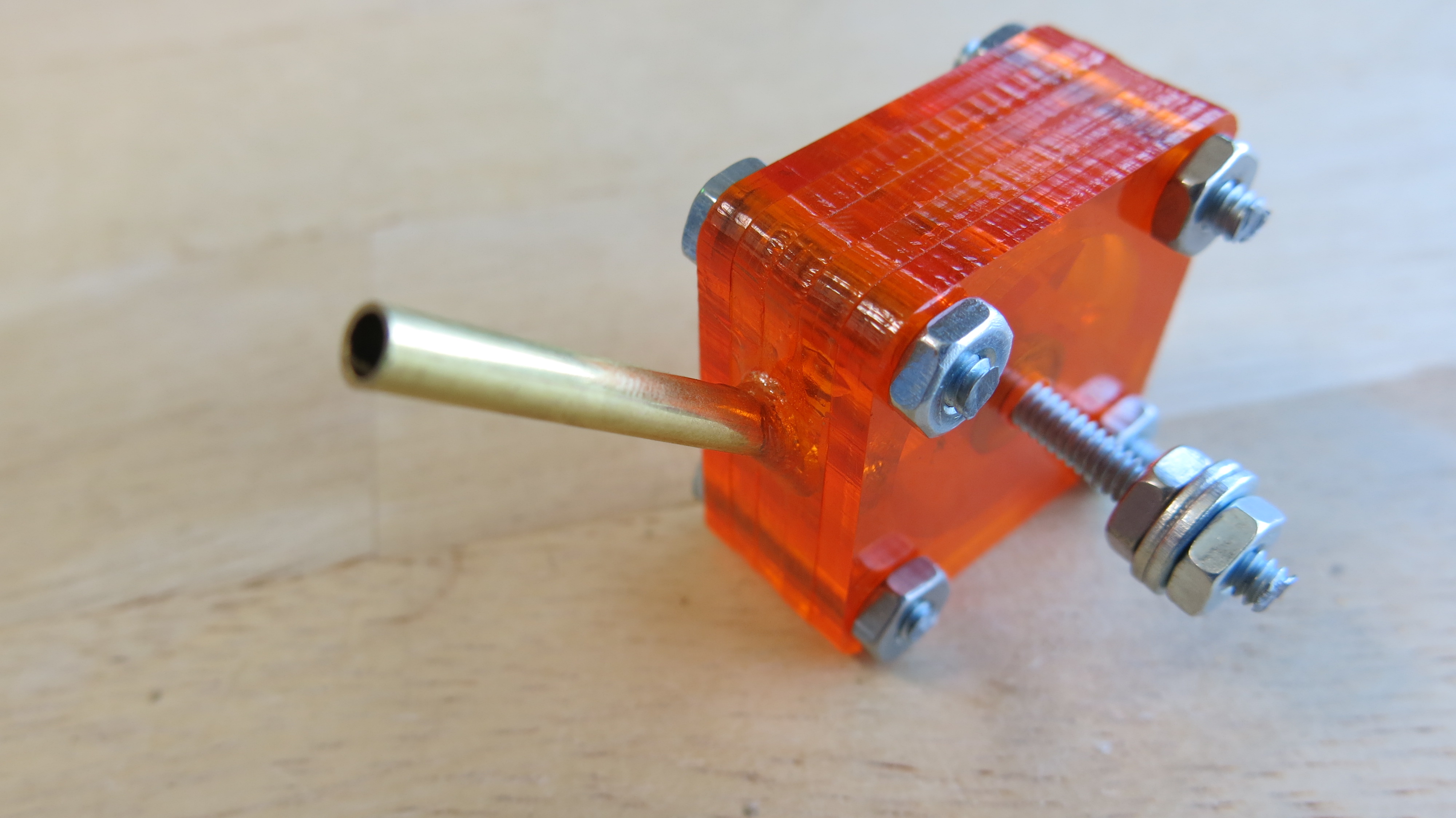
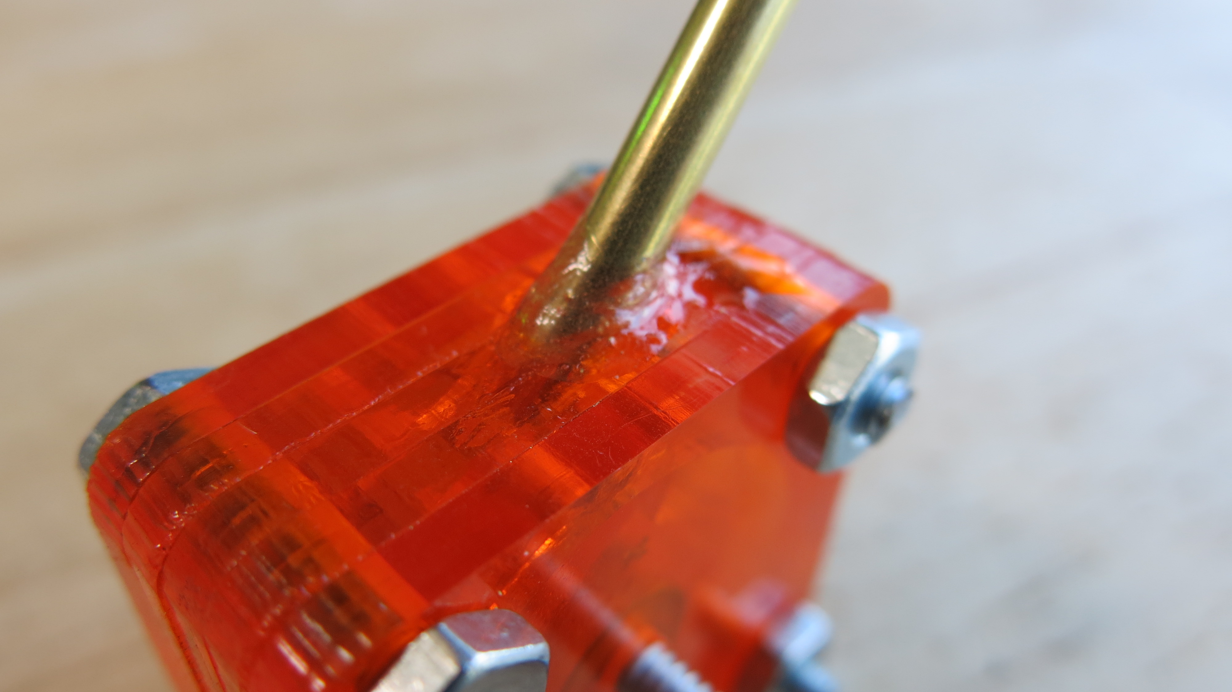
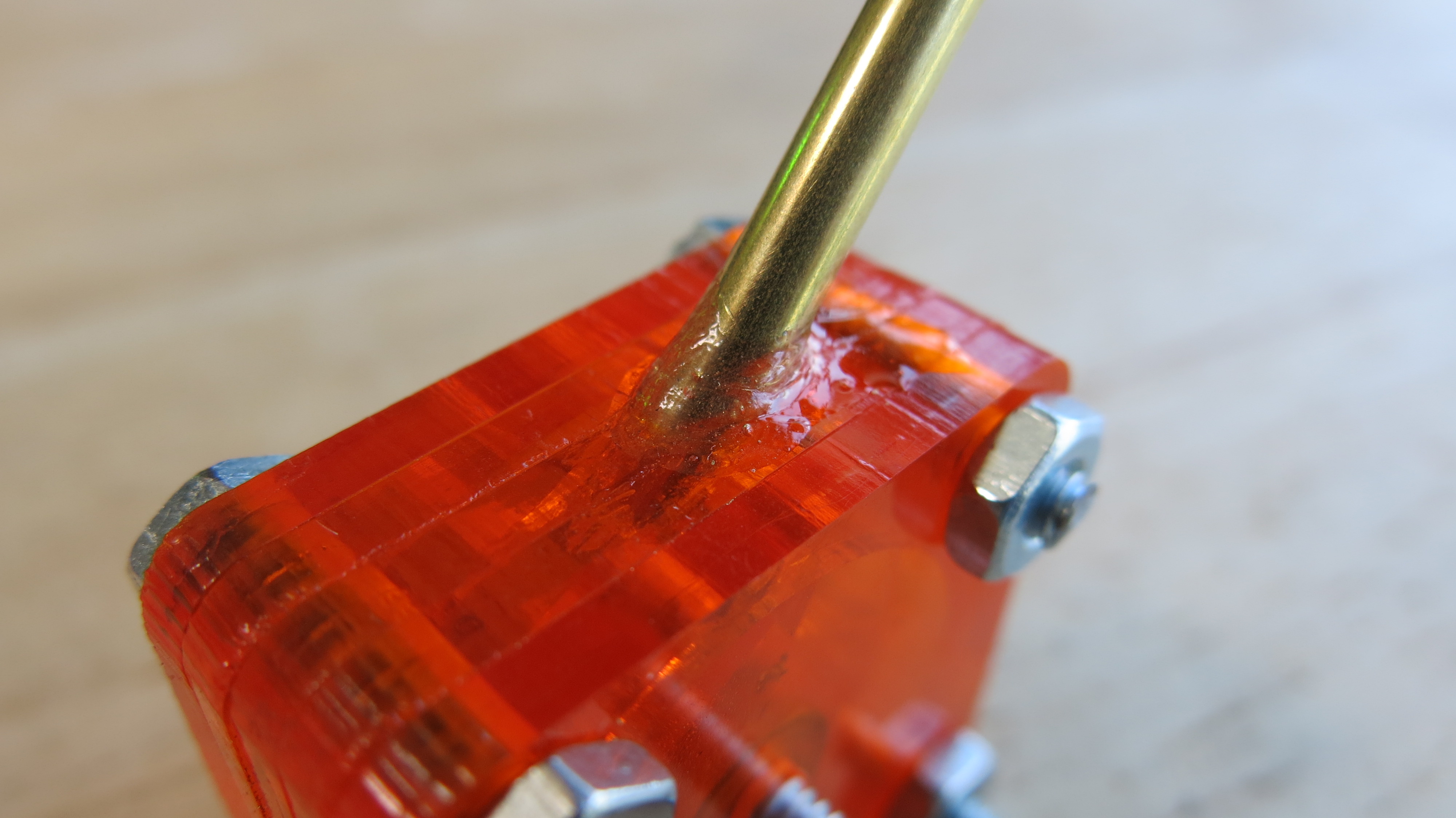
A small section of 1/8" brass tube was cut using a Dremel rotary tool, and the air intake was widened to allow it to be epoxied into place inside the turbine after it was bolted together.
Conclusion!
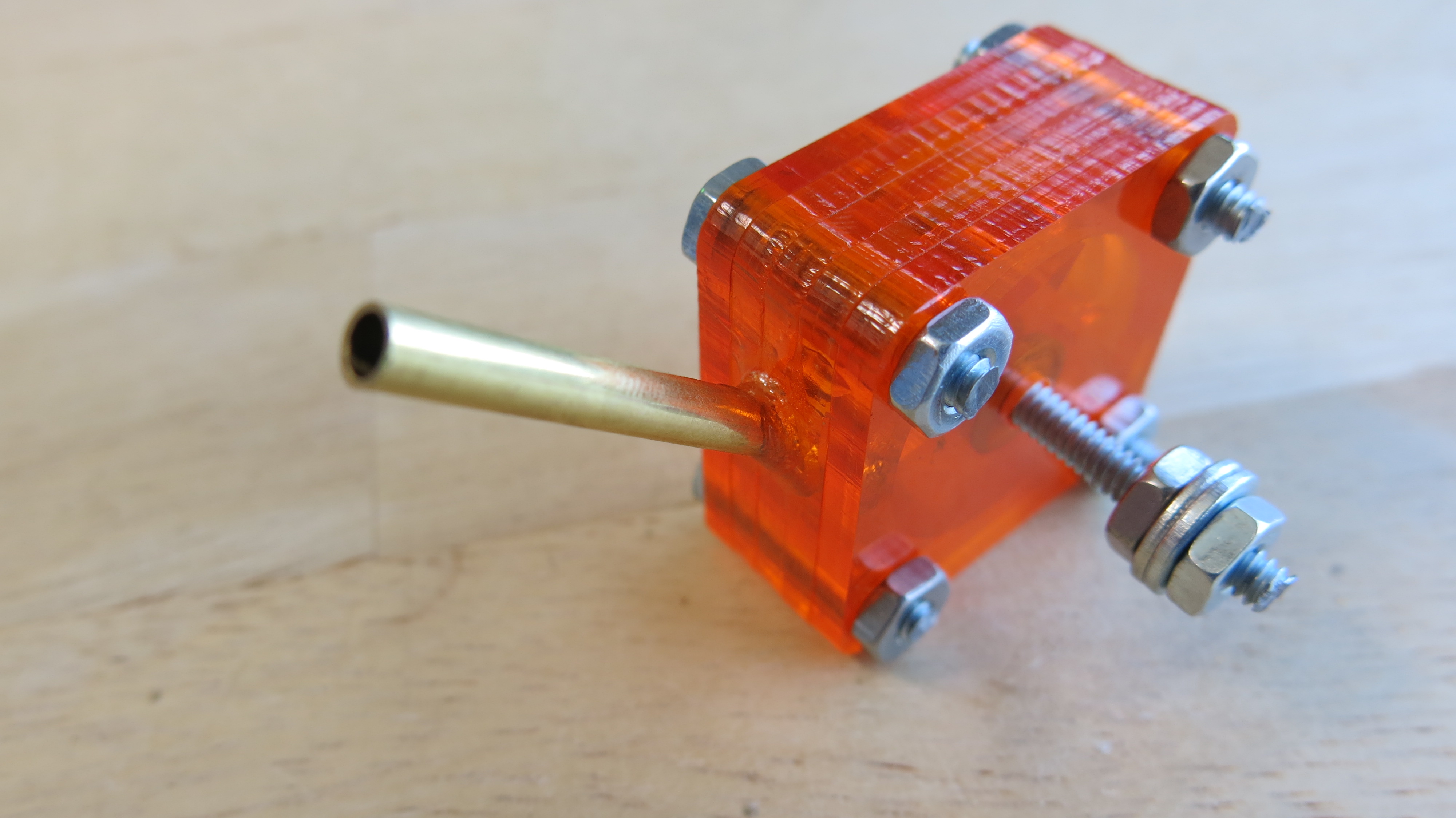
There you have it! A miniature compressed air turbine!
I'm not sure if I will ever use this for a project, but I may some day! More than anything, I've always found turbines fascinating, and love the sound they make when they get going. The possibilities for this little turbine are quite wide.
This design makes a small turbine, roughly 1.5"x1.5"x0.625" in dimensions. What I think is really awesome is that it can be made larger and theoretically more powerful by simply cutting and bolting in more layers for air input, more turbine pieces, and making more exhaust holes in the Exhaust-housing.
-
You should leave me a comment! I like those! They help keep me motivated to publish articles instead of letting the pictures I took rot on my hard drive! : )