How to Make a MIDI Theremin
by Bare Conductive in Circuits > Audio
13510 Views, 115 Favorites, 0 Comments
How to Make a MIDI Theremin
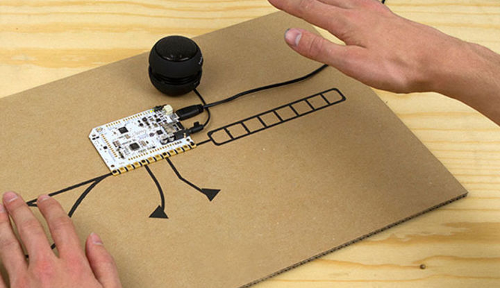
Use the Touch Board to re-imagine the Theremin!
For those of you who have not heard of a theremin, it is an early electronic musical instrument that is controlled or played without physical touch. The original theremin was designed by inventor Leon Theremin and patented in 1928. In a traditional theremin, the instrument is controlled via two metal antennae that sense the relative position of the player’s hands. One of the antennae is for controlling the frequency and the other for volume. The results is a wonderfully erie sound coming out of an instrument you don’t even need to touch! Although the metal pieces are called antennae, they are not broadcasting radio waves, but are working as plates of a capacitor. Enter the Touch Board…
For more project ideas visit www.bareconductive.com
Materials
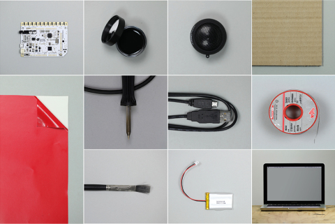
To begin you will need:
1x Touch Board
1x USB cable
—
1 x speaker or headphones
1 x computer
1x soldering iron and solder *
paper/cardboard
vinyl stencil
paint brush
* or use Electric Paint
Real Time MIDI Mode - Recap
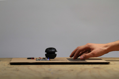
This tutorial is actually a follow-on from the On Board MIDI Mode tutorial where we set up the Touch Board to be a MIDI instrument – except in this case we will create a MIDI theremin. The previous tutorial explains how the Touch Board can be placed in “Real Time MIDI Mode” by bridging two sets of contacts and loading a particular Arduino sketch. We will go over a similar process too, but do check it out as it is a useful point of reference.
Connecting the MIDI Solder Bridges
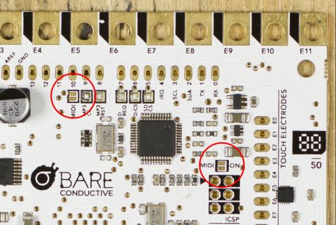
In the On Board MIDI Mode tutorial we placed the Touch Board into Real Time MIDI mode by using a soldering iron. For variation’s sake we will go with the alternative method of using Electric Paint to connect the solder contacts. The image along side shows the two sets of pads that need to be connected electrically on the Touch Board. The first link allows the MIDI chip to talk to the Touch Board’s microcontroller via digital pin 10, while the second link turns on the MIDI function on the chip.
Apply Electric Paint
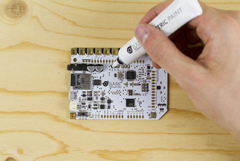
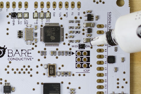
To connect these two sets of contacts, take your Electric Paint tube and carefully squeeze a small bead of paint directly over both pads. First experiment on a piece of paper to get a feel for the paint’s consistency and how fast it comes out.
Once it is applied take a close look to make sure it has stayed within the black bounding square graphic. Finally, leave it to dry for 10 minutes. If you need to remove the dry connection you easily pick it off with your nail, or wipe it off with a baby wipe.
Upload the MIDI Theremin Code
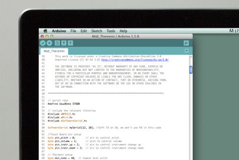
We now need to upload the MIDI theremin code to the Touch Board. We have Nathan Tomlin to thank for the code – he sent it over to us and gave us permission to share it with you!
Firstly, if you haven’t already completed our Setting up Arduino with your Touch Board tutorial, please do that before continuing.
Once this is done, plug the Touch Board into the computer via the USB cable. Make sure that the power switch on the board is set to ON. Open the Arduino IDE and then select the midi_theremin example under
File→Sketchbook→Touch Board Examples→midi_theremin
Ensure that Bare Conductive Touch Board is selected under
Tools→Board
and that the correct serial (CU) port is selected under
Tools→Port
With all of the correct settings selected, click
File→Upload
to push the code to the Touch Board. The RX and TX LEDs will flash on the Touch Board and the Arduino IDE should say “Done uploading”.
With your Touch Board still connected to the computer test the program by opening the Arduino serial monitor in the top left hand corner of the programming environment. Next touch electrode E0 (Pitch), then wait a second before touching E11 (Volume). This is to calibrate the sensors. Now if you touch E0 and E11 you should see text in the serial monitor about the volume level and the notes being played. Touching E4 and E7 changes the instrument selected forwards and backwards respectively.
If there are any issues check that the solder connections are properly bridging the two pads mentioned in Step 3 above.
Paint Your Interface - Screen Printing
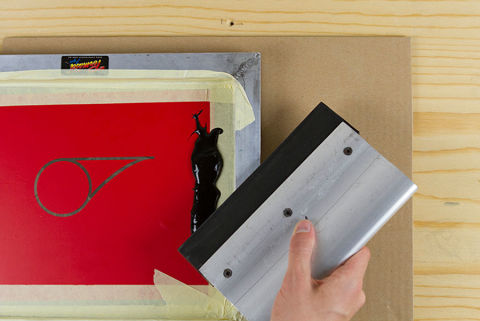
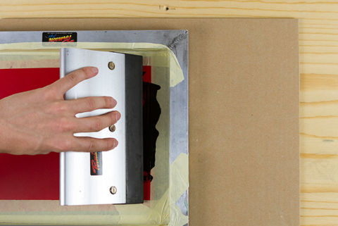
Now let’s break out the electrodes used in the MIDI theremin code onto a material of your choice and make it interactive with Electric Paint! There are many ways to do this, but we have chosen to illustrate three different methods for comparison.
For the volume control sensor (E11) we decided to use screen printing, which gives a nice precise graphic. Normally you expose a light-sensitive substance to generate the stencil on the screen mesh, however, we have used a vinyl cutout as its much quicker for quick prototypes.
Paint Your Interface - Vinyl Cutout
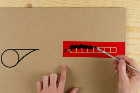
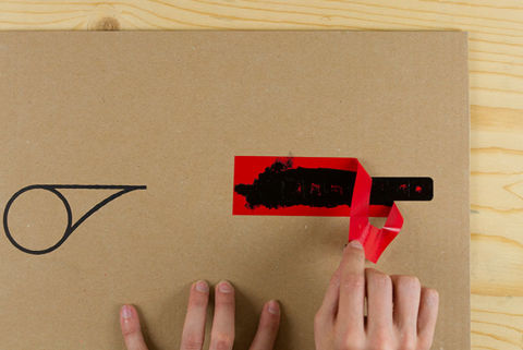
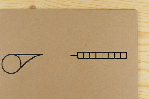
If you don’t have any screen printing kit, do not fear. A vinyl stencil can be used without the screen mesh and squeegee. For the pitch control sensor we used a vinyl stencil transferred directly to the cardboard where we then use a paintbrush to apply the paint.
Paint Your Interface - Touch Board Stencil
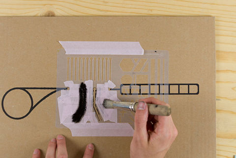
Finally, to create the buttons that cycle between instruments (E4 + E7) we used the Touch Board stencil. When using the Touch Board stencil make sure to use a sponge or stencil brush to get the best results.
Cold Solder the Electrodes
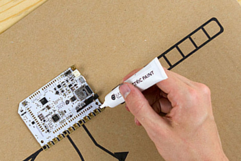
Once your painted or printer graphics are dry, you can position your Touch Board carefully on top. Use Electric Paint to cold solder the electrodes to the graphic. Check out our tutorial on how to do this using the link below.
Plug and Wave
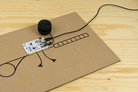
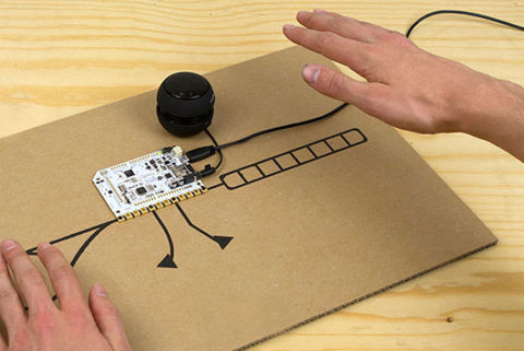
Power up the Touch Board by plugging in a battery or USB cable, making sure that the board is switched on. Connect a speaker or headphones for sound. Calibrate the pitch and volume sensors by touching each of them briefly. Now start conducting some music without touch. Cycle through the instrument library using electrodes E2 and E3 and see which one most resembles the original theremin’s unique erie sound.
If you liked this tutorial visit www.bareconductive.com for more!