How to Make a Light Detector With Analog-to-Digital & Comparator Module
by mybotic in Circuits > Electronics
2468 Views, 5 Favorites, 0 Comments
How to Make a Light Detector With Analog-to-Digital & Comparator Module
.png)
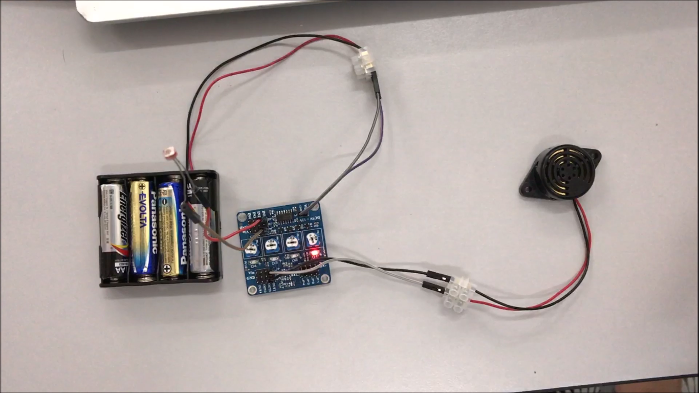
This tutorial is give some basics on how to create a light detector using a Light Dependent Resistor (LDR), a buzzer and an Analog to Digital & Comparator Module. This Instructable will also show a video demonstration when light is detected, the buzzer will ring.
Introduction
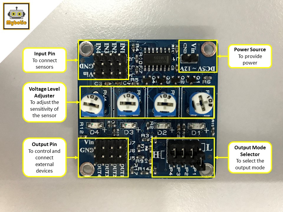
The Analog to Digital & Comparator Module is a module that converts the analog signal to digital signal. It is using the LM339 as a comparator to compare the incoming voltage and the preset voltage. Thus, it is called comparator module. After comparing the incoming voltage and the preset voltage, it will give an output either active high or active low depending on the user’s setting. Analog to Digital & Comparator Module consists of 4 channels for the inputs and outputs. The on boards’ presets are used to set the compare voltage level.
Specifications
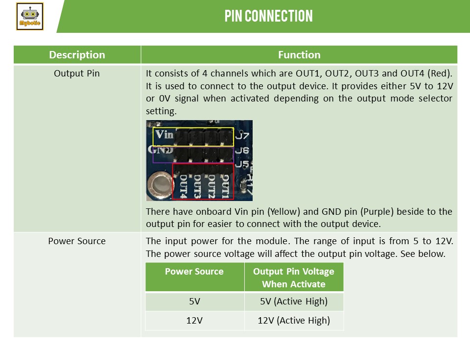
- Operating Voltage : 5-12 VDC
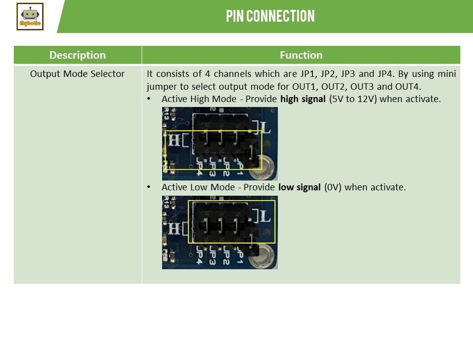
- Output Signal : Selectable either Active High or Active Low Digital Signal
- Board Size : 45mm x 45mm
- Channels : 4 Inputs Channel, 4 Outputs Channel
Material Preparation
For this tutorial, you need to have the following items:
- Analog to Digital & Comparator Module
- Light Dependent Resistor (LDR)
- Female-to-Female and Male-to-Female Jumper Wires
- Buzzer
- 4 x AA Batteries
Pin Definition
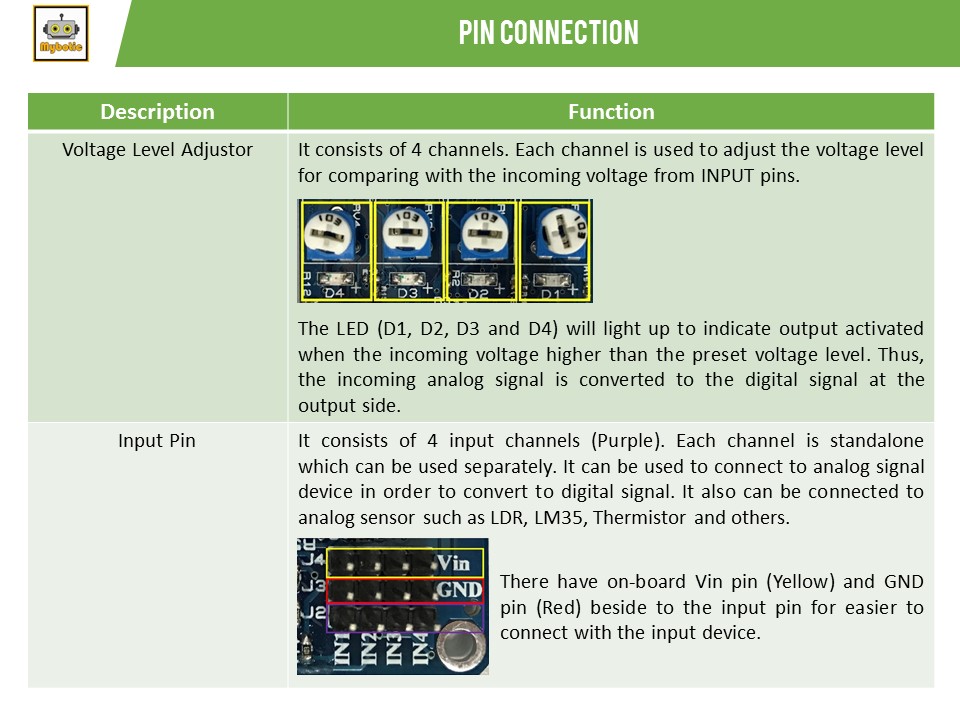
Circuit Assembly
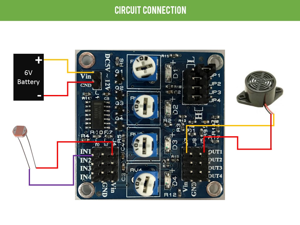
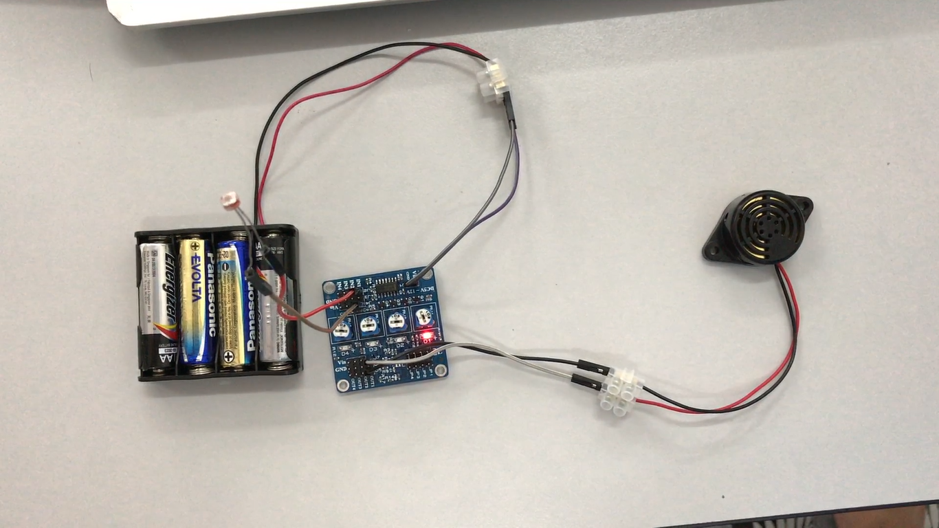
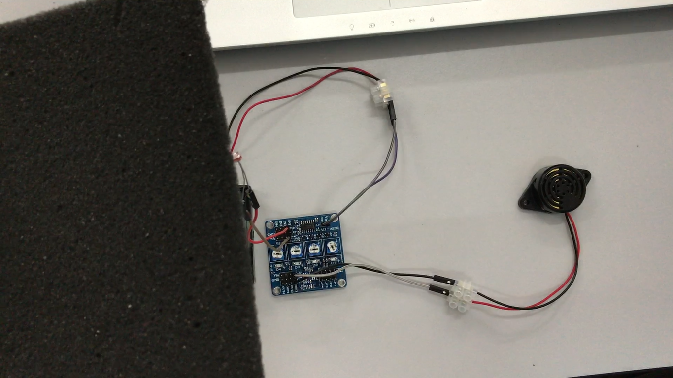
The Analog to Digital & Comparator Module can be used as a light detector by connecting the LDR which is an analog type. The module converts the analog signal from LDR to digital signal and activates the output. In this example, the buzzer act as an output.
Change Output Mode
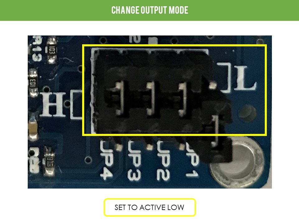
After completing the connection, change the output mode to Active Low by removing and placing back the mini jumper.
Setting Up the Preset Compare Voltage
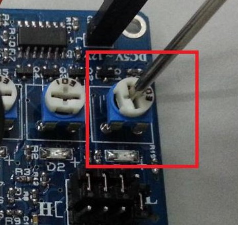
To adjust the preset compare voltage and the LDR sensitivity, tune the Voltage Level Adjustor (Potentiometer) for the desired threshold for the LDR to detect light and turn on the buzzer.
Results
.png)
.png)
Based on the results, the LED (D1) and the buzzer is on when the light is present. This indicates that the voltage from the LDR is increased due to the temperature increase. When the voltage from LDR increases until higher than the preset compare voltage, a high signal (6V) is giving to the output pin 1 (OUT1) which will then activate the buzzer.
Video
