How to Make a Gear in Fusion 360
by Maxim_glu in Design > 3D Design
806 Views, 4 Favorites, 0 Comments
How to Make a Gear in Fusion 360

Welcome to your step-by-step guide on how to make a gear in Fusion 360. If you are into design and engineering this is for you. Below, you will find a clear, step-by-step tutorial that will guide you in creating from scratch, in Fusion 360, a functional gear. Learn the essentials in CAD design for a total beginner or strengthen your skills. Now, let's enter into custom precision design and bring your custom gear to life!
Here is the video where you can watch how to make the gear - https://www.canva.com/design/DAGQ-FTia90/wkgv5R2l929jlqds3sqpwA/edit?utm_content=DAGQ-FTia90&utm_campaign=designshare&utm_medium=link2&utm_source=sharebutton
Supplies

For this project you will only need Fusion 360, I also attached a file with my previous gear if you want to take a look at it.
Downloads
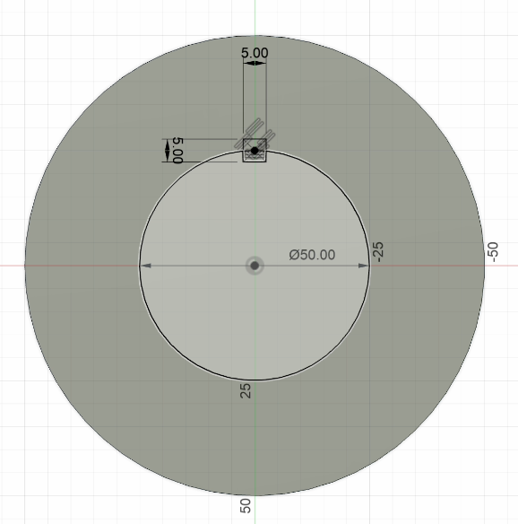
Creating the Base Circle
Open fusion 360. At the top left corner you click at the button to "create sketch" then click "create" button and choose a circle, make sure it is “Center Diameter Circle” , place it directly in the middle and make it any diameter you want. After that you click “finish sketch” and click “extrude” at the top left corner choose “direction” and make it “symmetric” then click on your circle and make it as thick as you want.
Adding the Inner Circle and Keyway
After you are done extruding your gear we will start doing an inner circle. Click “create sketch” and choose the circle you just made. Choose “Centre Diameter Circle” , place it directly in the middle and make the second circle which should be smaller than the first one. Then click at "create" button again and choose “Center Diameter Rectangle” and place it on the outer line of inner circle(check the photo), it will be our keyway*. When you've placed it choose the dimensions for it, when you are done with choosing the dimensions of one side click tab and choose the dimensions of the other side.
*Keyway - The main purpose of said keyways is to prevent components from slipping on and rotating independently from the shaft they're mounted on, which adds torque capacity in driven systems.
Hollowing the Gear
Click on the "extrude" button and select the inner circle with the rectangle that we drew and then push it through our gear to make it empty inside.
Creating Additional Circles
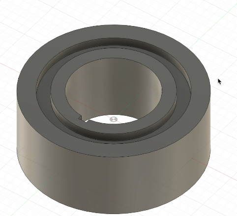
Click “create sketch” and choose “Centre Diameter Circle” and draw two more circles around the inner circle which are smaller than the outer circle. When you are done drawing you click “extrude” and push it inside our gear a little bit depending on how thick your gear is.
Mirroring the Feature
Now we need to mirror the side and click the “Create” button. Be careful it is not the “Create Sketch” button we scroll down to the end and choose “Mirror”. In the pop up we instead of “bodies” we choose "features” after that we select the last circle that we did, which we extruded . Then we click on the "mirror plane" and choose the yellow side inside(watch video carefully at 1:04 to understand). Now that we are done with the body it is time to do the teeth.
Designing the Gear Teeth
Click on “create sketch” and depending on what you want your teeth to be like choose either "line" or “conic curve” . Start drawing on the outer circle and make sure that all your lines connect making some kind of a figure because without that it wont work. Watch the video to understand.
Finishing Up
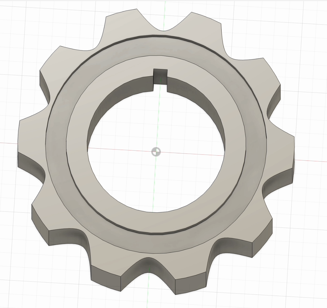
After you are done with drawing one tooth of your gear you click "extrude" and pull it back to make it empty. Now you click “create” find “pattern” and there you choose “circular pattern” make sure that the object type is “features” you click on the part which you just emptied out and after that you click “axis” and choose the lateral side of the gear and put as many teeth as you want. Done.