How to Make a Basic Drawing With Onshape
by dagan-trnka in Teachers > University+
1874 Views, 0 Favorites, 0 Comments
How to Make a Basic Drawing With Onshape

Technical drawings are an important aspect of engineering communication. They are one of the best ways to accurately and unambiguously capture all the geometric features of a product or a component. When using CAD software to design parts, creating technical drawings is relatively straightforward.
Create a Drawing From a Part/adding Views

To begin drawing, create a drawing from your part in Onshape. While in your part workspace, go to the bottom left of the window and click on the plus button. Select "Create Drawing..." from the menu that pops up. Select a template for your drawing. Go to the Onshape filter and select either ANSI_A or ANSI_B. You can choose either metric or inches to work with. If using ANSI_A, you may need to use a 1:2 scale to fit your part on the drawing.
After selecting your template, you will be brought to a new tab with a blank drawing displayed. Select your part from the menu that pops up.
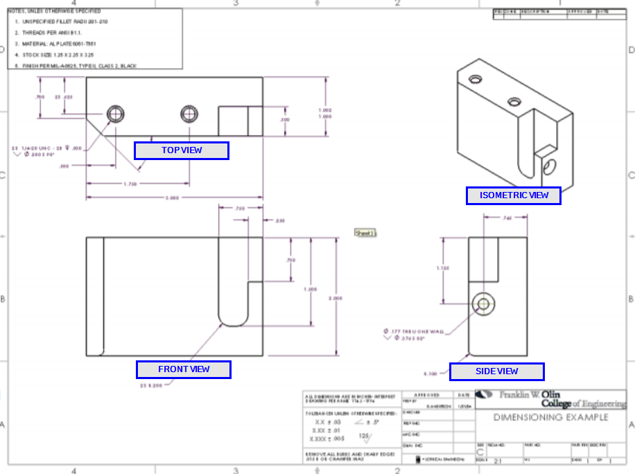
If you move your mouse around the drawing, you'll find that you're already dragging around a view of your part. If the view takes up more than a 1/4th of the page, change the view scale in the top left corner. To place this view, click somewhere on the drawing; conventionally, you'll place the first view around the bottom left. After you've added the first view, you can add additional views by clicking on the base view, and moving your mouse to the sides of the base view. Go ahead and place a front, top, side, and isometric view. See the image at the top of this Instructable to see what those are.
To add a cross-sectional view, click "Section View", then click on a view from which to take a cross-section. Select two points to form a line -- a new view will pop up where your mouse pointer is. The new view will display your part as seen when cut along the line you defined.
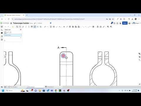
To add a detail view, click "Detail View", then choose a view from which to show details. Click to choose the center of the detailed circle, then click again to choose the radius. The part of the view inside the circle you create will be used to create an enlarged, detailed view.
Technical drawings are intended to communicate all features of a part, often so that the part can be replicated accurately. Include as many views as necessary to achieve this goal and accurately communicate all of the part's features.
Dimensioning a Drawing

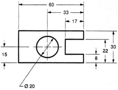
Once you've added enough views to capture the part, you can start adding dimensions. Dimensions communicate the size and shape of your part. To add a dimension, press D or click on the dimension icon along the top toolbar. This tool will select the appropriate kind of dimension for any measurement on your part. The tool works in exactly the same way as the dimension tool for modeling. However, unlike the modeling tool, this dimension tool does not set dimensions. Rather, it displays existing dimensions from the part.
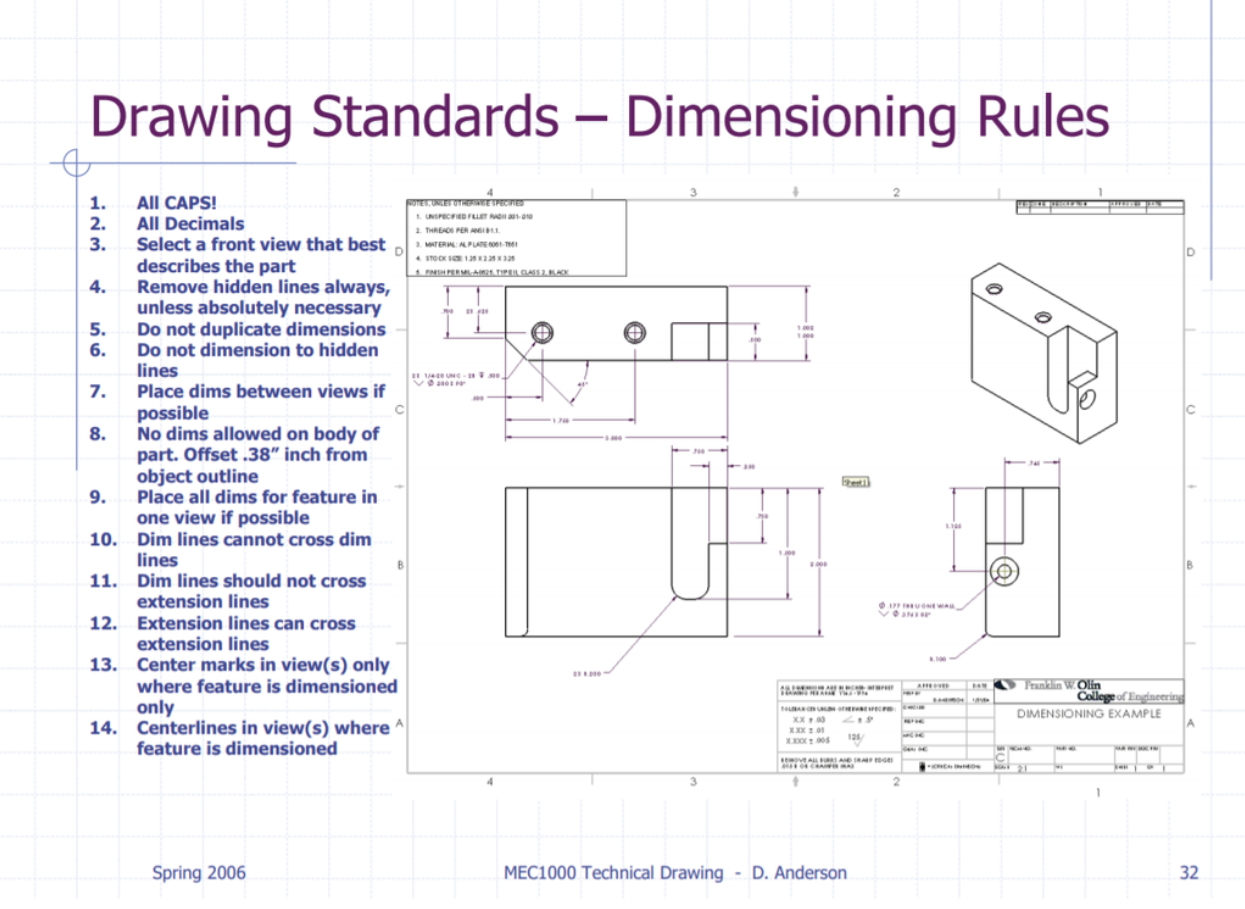
Drawing Standards

In general, follow the drawing standards and dimensioning guidelines given in the image above. By following these guidelines, you can create professional-looking, clean, and easily understandable drawings.