How to Make a 3D Printed Miter Guide With Fusion 360
by Great Lakes Makes in Workshop > 3D Printing
7838 Views, 93 Favorites, 0 Comments
How to Make a 3D Printed Miter Guide With Fusion 360
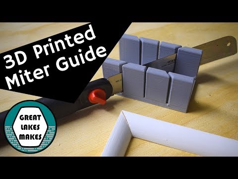
I’ve got a lot of trim work to finish up in the house, and
it doesn’t make sense to haul the miter saw from room to room just to cut quarter-round. I needed a small miter guide for the smaller bits, so I designed and 3D printed this small guide and it’s been the perfect solution. Read on, and I’ll show you how I did it.
You can watch the video to see how I designed the part in Fusion 360, using the mirror and combine functions. The final part was printed on the Monoprice Select Mini 3D printer in PLA.
STL File is posted here
Start With a Sketch
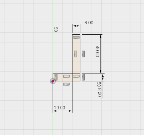
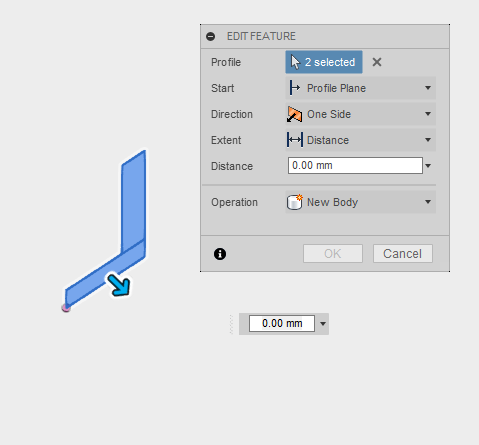
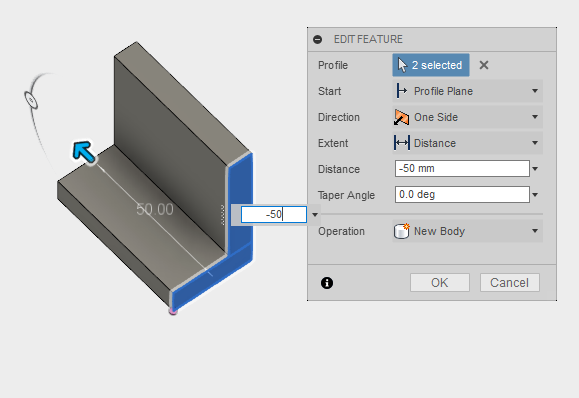
Starting in Fusion 360, create a new component and start a sketch on one of the vertical planes. You can save some time by using two simple rectangles in a backward L-shape; make the bottom leg start at the origin. You could go back and trim away the overlapping lines, but it’s not necessary.
Add dimensions to the sketch:
- Make both legs 8mm thick; this gives enough guide for the sawblade as well as thick enough to be stiff.
- Set the vertical leg 20mm from the origin; when the part gets mirrored, that will leave a 40mm opening.
- Make the vertical leg 40mm tall; these dimensions will leave just enough space to cut a standard 1x2.
Stop the sketch and use the Extrude tool to pull both rectangles out to 50mm; once the part is mirrored the total length will be 100mm. This will fit easily on the Monoprice Select Mini build plate.
Cutting the First Slot
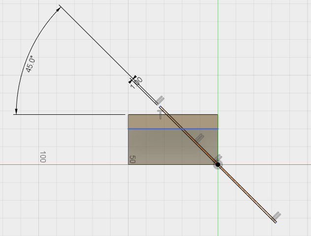
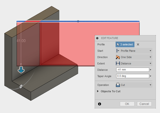
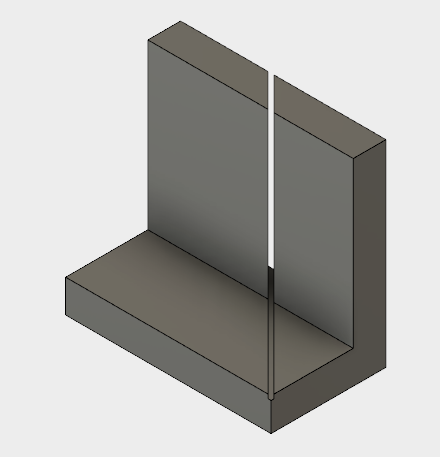
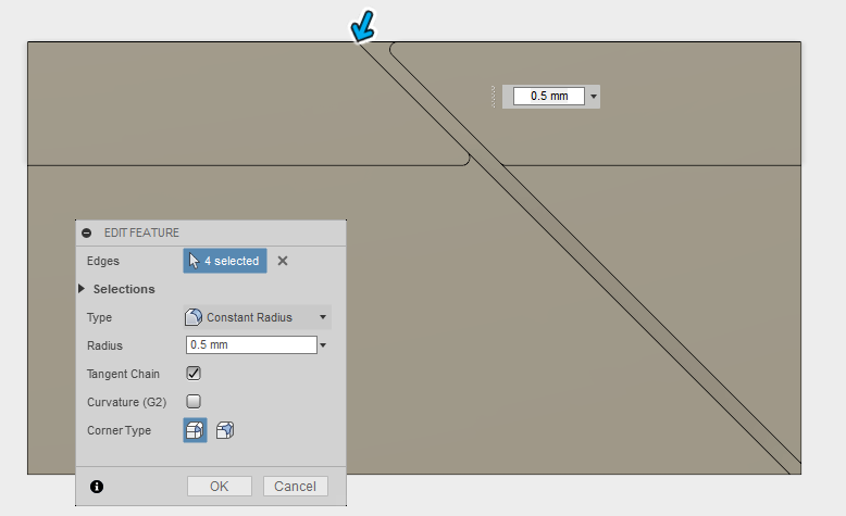
To create the cutout slots for the sawblade, start a new sketch on the top surface of the vertical leg. Using the ‘Center Rectangle’ sketch too, draw a narrow rectangle centered at the origin. This tool automatically creates several constraints, and you’ll need to find the ‘Horizontal’ constraint and delete it. This will let you grab one of the corners of the rectangle and rotate it up into position.
Next, add a dimension to hold the rectangle at 45 degrees from the edge of the guide and set the width to 1mm; then exit the sketch.
Use the Extrude tool to pull the slot down into the body by 41mm, cutting a slight sawblade relief into the bottom surface. Make sure to grab both pieces of the rectangle when you cut both the leg and the bottom panel.
Now is also a good time to add some fillets to the slot, it saves time to mirror as close to a finished body as you’ll have to select only four edges instead of 16.
The First Mirror and Combine
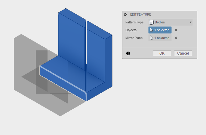

With the slot cut into the leg, we can start to build out the finished part using the Mirror and Combine tools. Under the ‘Create’ menu, find the ‘Mirror’ tool. Make sure the Pattern Type is set to Bodies in the Edit Feature window that pops up. Select the solid as the Object and use the vertical face of the bottom surface as the mirror plane to create a U-shaped body and hit OK.
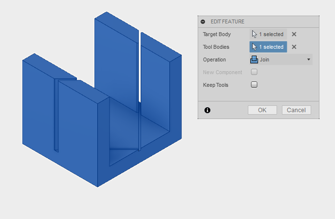
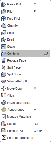
When the part mirrors, you should see a line down the center of the body. This is an indication that you have two solids instead of one. Under the ‘Modify’ menu, select the ‘Combine’ tool. Select one side as the Target Body and one as the Tool Body and click OK. The line down the center will be gone and you’ll have a single solid body.
Add a Hole to the Bottom
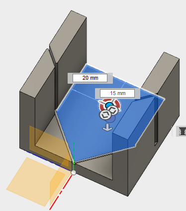
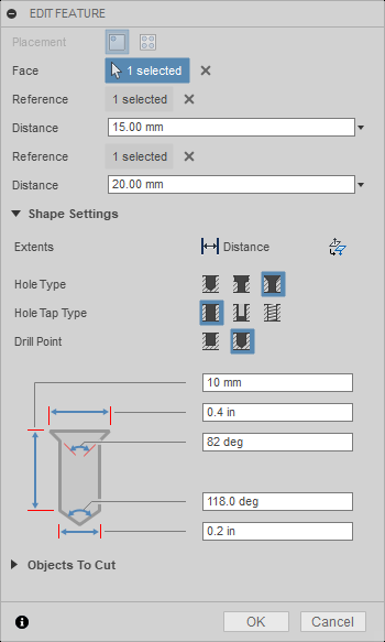
Next, I’d like to add some holes to the bottom of the guide so that I can screw it down to a workbench if I want to. It’s best to think about these added features now than to try and come back and modify the printed part later.
Under the ‘Create’ menu, select the ‘Hole’ tool and click the bottom surface of the guide. In the Edit Feature window, select the Countersink shape as the Hole Type.
I used the following dimensions to fit a No.8 wood screw:
- 10mm for the depth
- 0.4in as the head diameter
- 82 deg for the head angle
- 118 deg for the tip angle (but this really doesn’t matter)
- 0.2in for the hole diameter
At the top of the Edit Feature window pick the first Reference as the open end of the U-channel and enter 15mm. Then select one of the edges of the inside of the U-channel and enter 20mm. This will locate the hole in the center of the U and out of the way of the saw blade.
The Second Mirror and Combine
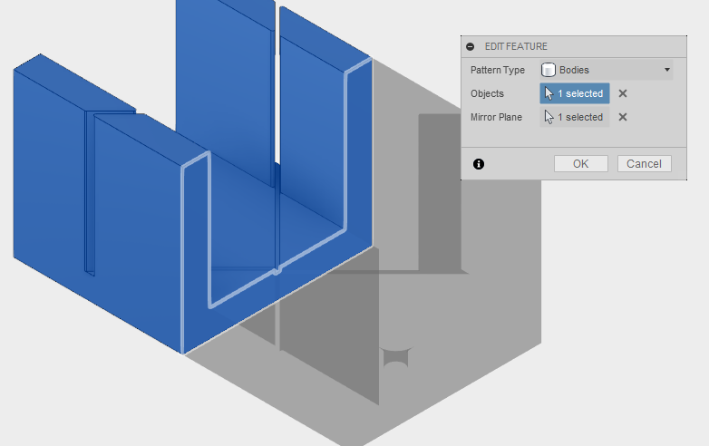
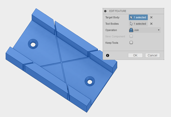
Again, use the Mirror and Combine tools to double the solid body across the origin to finish out the saw blade slots to form an X-shape. Under the ‘Create’ menu, find the ‘Mirror’ tool. Make sure the Pattern Type is set to Bodies in the Edit Feature window that pops up. Select the solid as the Object and use the vertical face of the U-channel, at the origin, as the mirror plane and hit OK.
When the part mirrors, you’ll still see a line down the center of the body. Under the ‘Modify’ menu, select the ‘Combine’ tool to again combine the bodies into a single solid. Select one side as the Target Body and one as the Tool Body and click OK. The line down the center will be gone and you’ll have a single solid body.
Cutting the Straight Slot
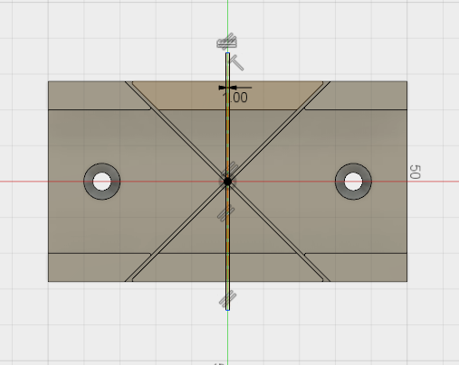
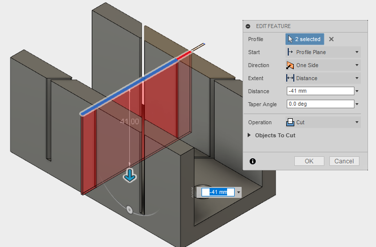
The last feature to add to the miter guide is a straight slot for making 90 degree cuts. We’ll add this right in the center of the guide. Create another sketch on the top surface of the legs and use the ‘Center Rectangle’ tool under the Sketch menu to draw a vertical shape with the center at the origin. Dimension the slot at 1mm in width and make sure it extends across the entire body. Exit the sketch and use the Extrude tool to pull the cut through the guide to a depth of 41mm; providing for a small relief at the bottom for the sawblade.
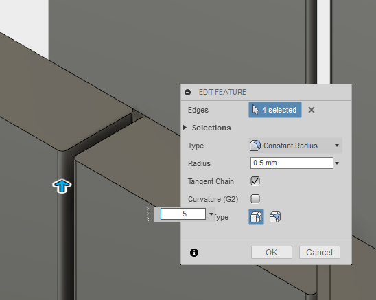
Once the slot is cut, come back with the fillet tool under the ‘Modify’ menu and add 0.5mm fillets at all the edges of the slot. These small round-overs will improve the overall quality of the print because the nozzle will struggle to make a perfectly sharp corner, and you will often end up with small bulges. Adding a rounded corner generally alleviates this problem.
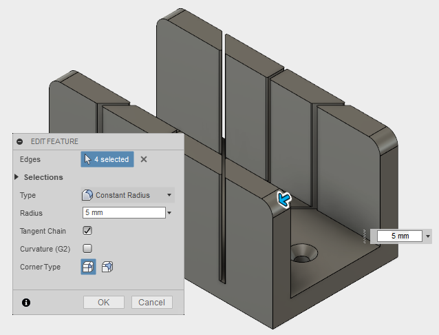
Finally, I added a 5mm radius on the top corners of the legs, just to make the part look a little more finished.
Let's Print It!
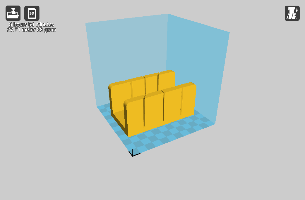
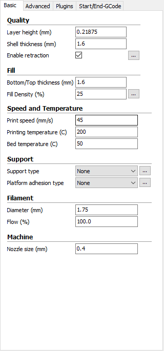
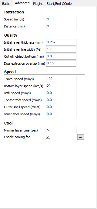
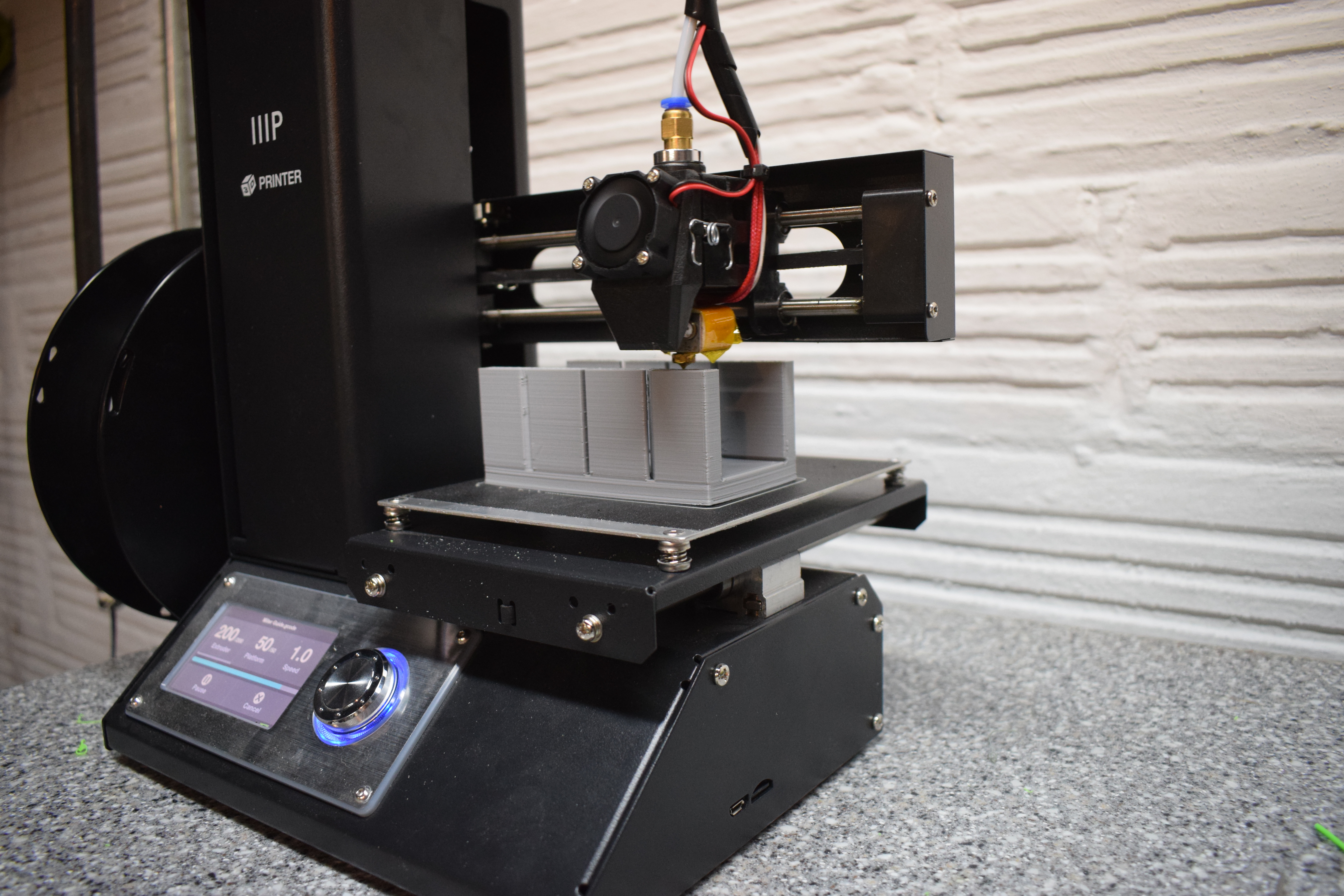
Export the models out to Cura, or the slicing software of your choice, and adjust the parameters to suit the parts. I wanted this to be a very durable print, so increased the shell thicknesses and infill percentage higher than I usually use.
Slicing Parameters:
- Layer Height: 0.21875mm
- Shell Thickness: 1.6mm
- Top and Bottom Thickness: 1.6mm
- Infill: 25%
Put It to Use
.jpg)
.jpg)
.jpg)
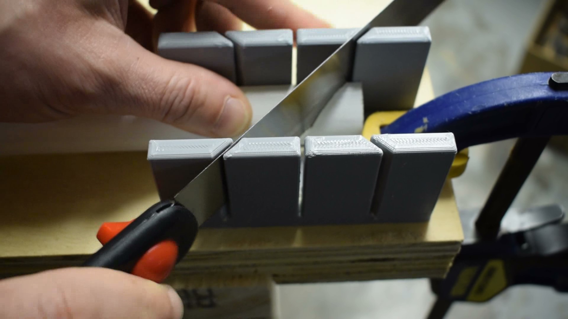
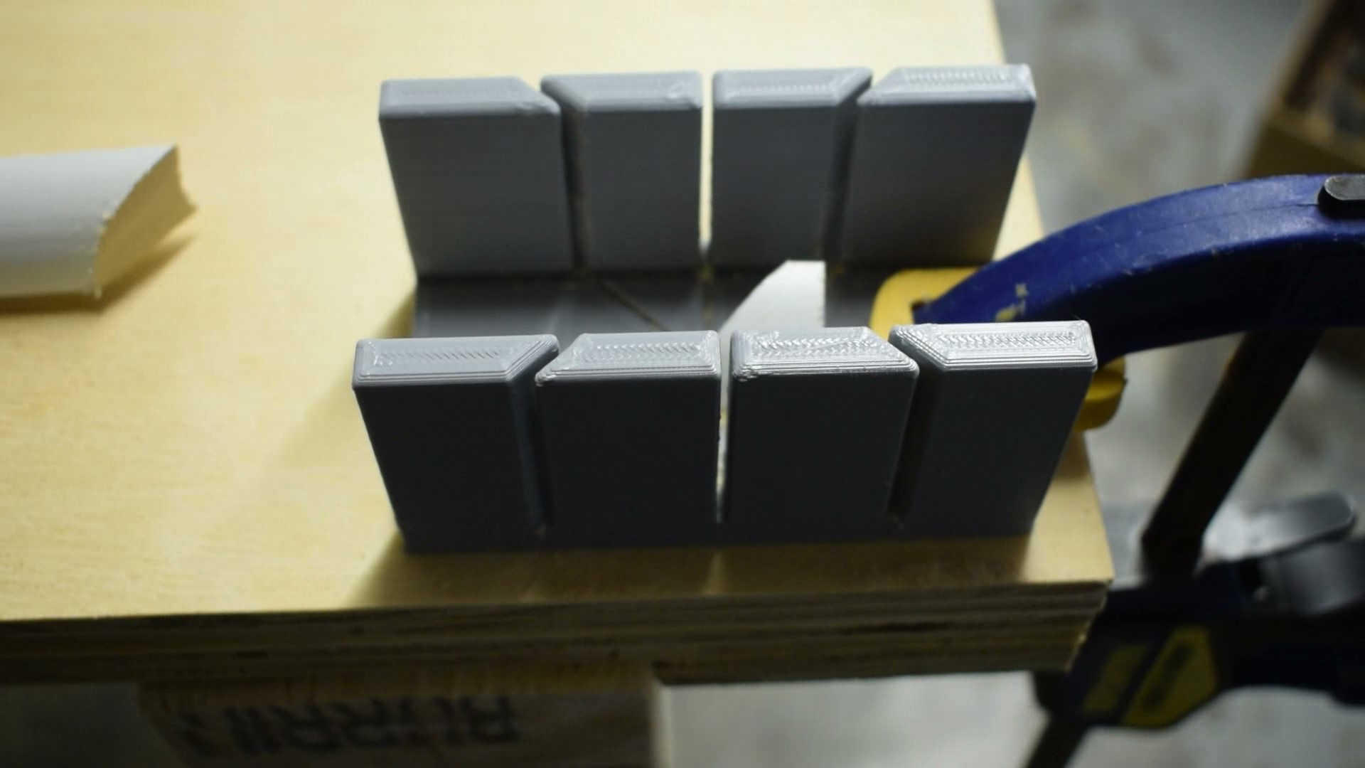
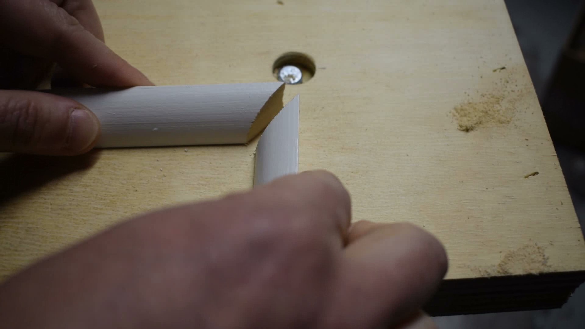
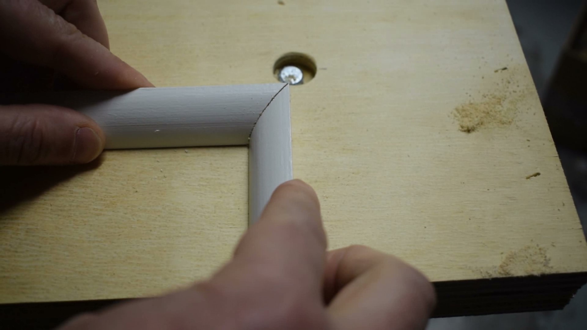
Right off the printer you can put this part to use. This miter guide is small and protable and makes quick work of quarter-round. With slots in both directions, it’s easy to cut miters for both inside and outside corners.
The Finished Product
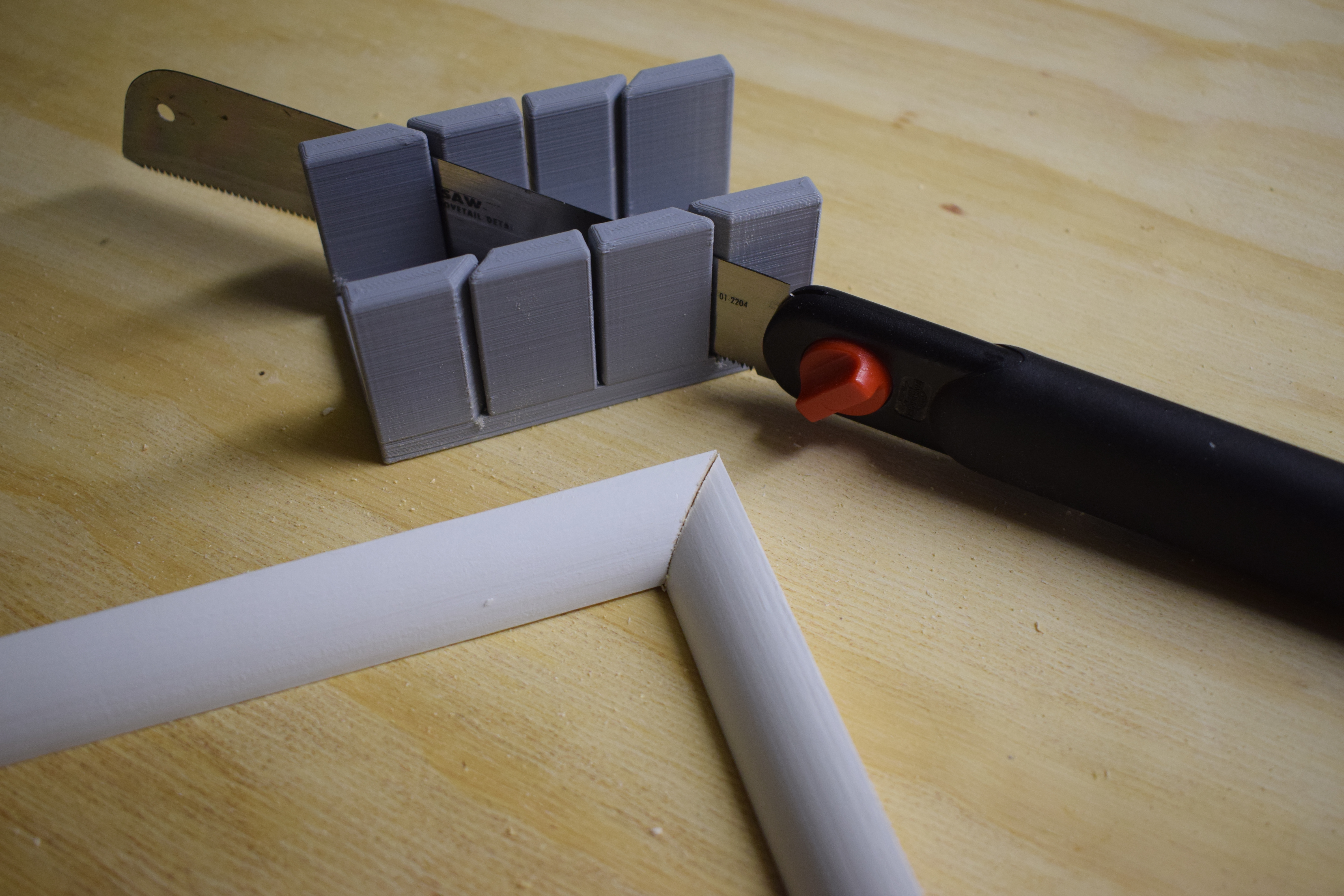
Thanks for reading, I hope you enjoyed this tutorial on Fusion 360 and how to design functional tools for 3D printing. If you want to see more of what I’m working on, check out the links below.
See you next time!
-------------------------------------
You can also find me at:
YouTube (all my DIY videos)
Instagram (What I'm working on @greatlakesmakes)
My Website (Geek out on some engineering know-how)
Facebook (be my friend?)
My Mini Factory (download the STL files)
-------------------------------------