How to Make Radio AM, Assembly & RUN
by inventor KR in Circuits > Wireless
1407 Views, 2 Favorites, 0 Comments
How to Make Radio AM, Assembly & RUN
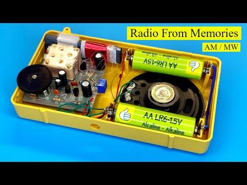
To make a simple AM radio using the TA7642 integrated circuit, also known as the MK484, you'll need a few components and basic soldering skills. Here's a basic schematic and a step-by-step guide:
Supplies
### Components Needed:
1. TA7642 IC (or MK484)
2. Variable capacitor (tuning capacitor)
3. Ferrite rod antenna
4. Inductor coil (optional, for better performance)
5. Capacitors (electrolytic and ceramic)
6. Resistors
7. Potentiometer (optional, for volume control)
8. Headphones or a small speaker
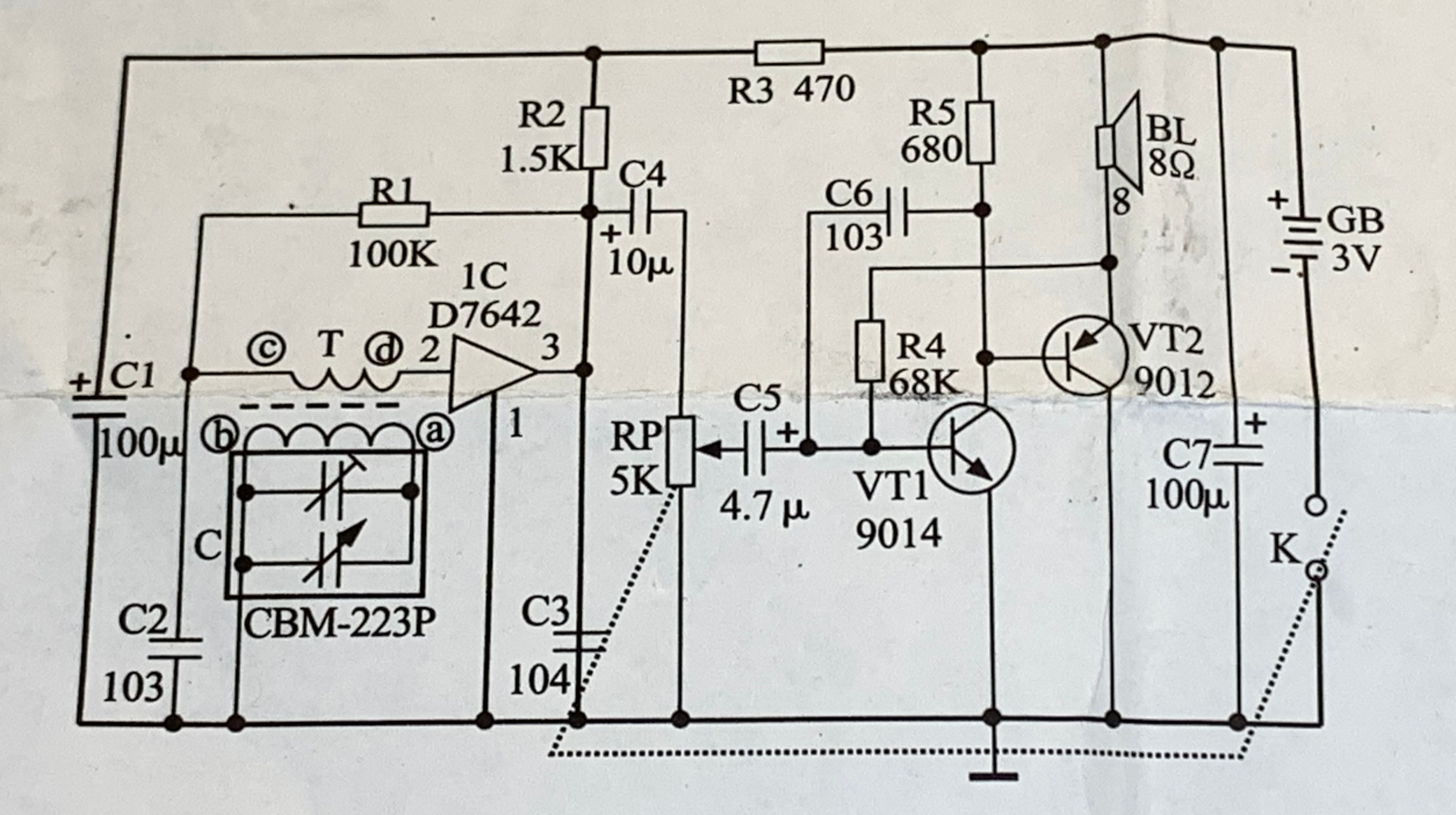
### Circuit Diagram:
Steps to Build
.png)
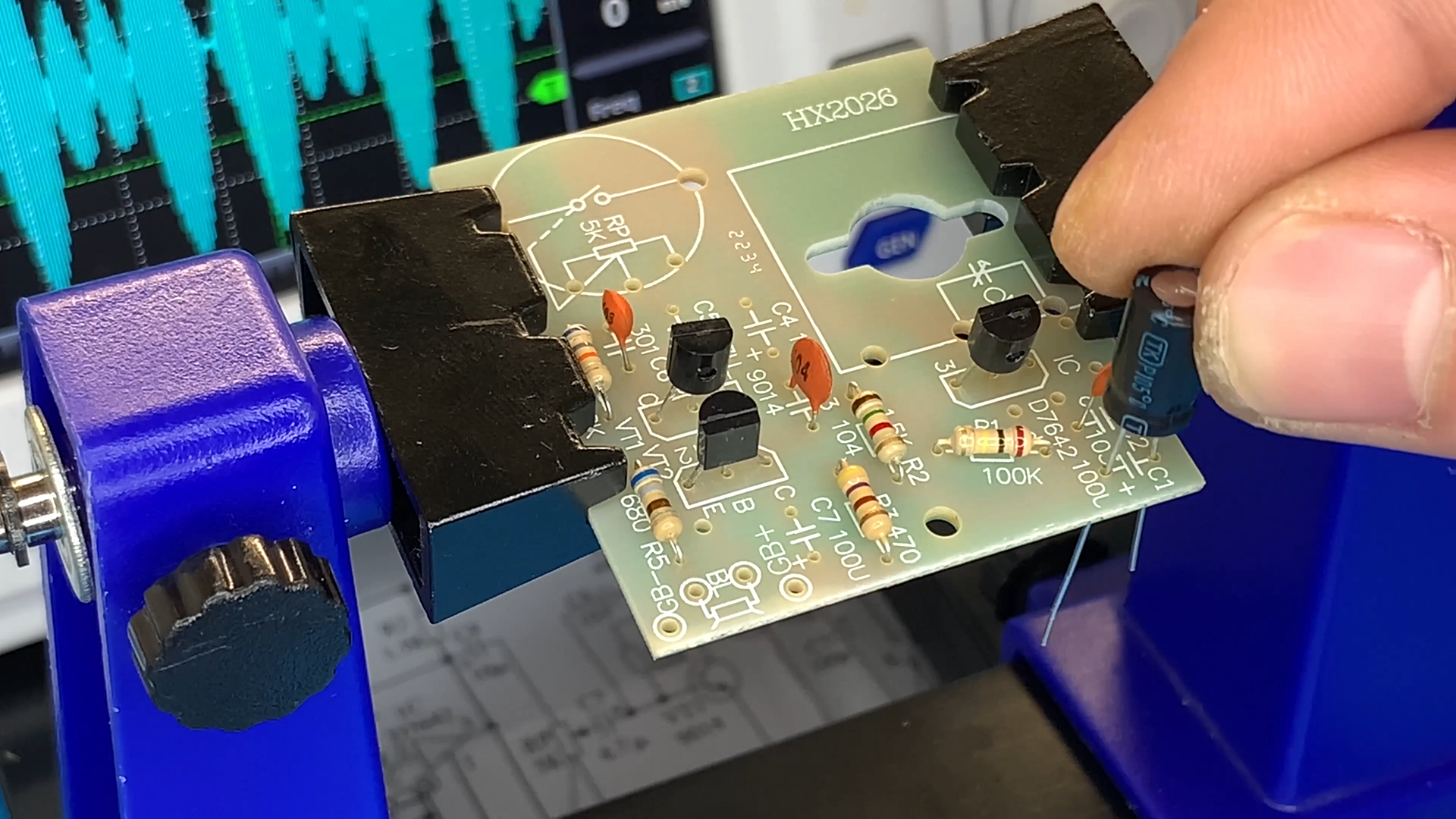
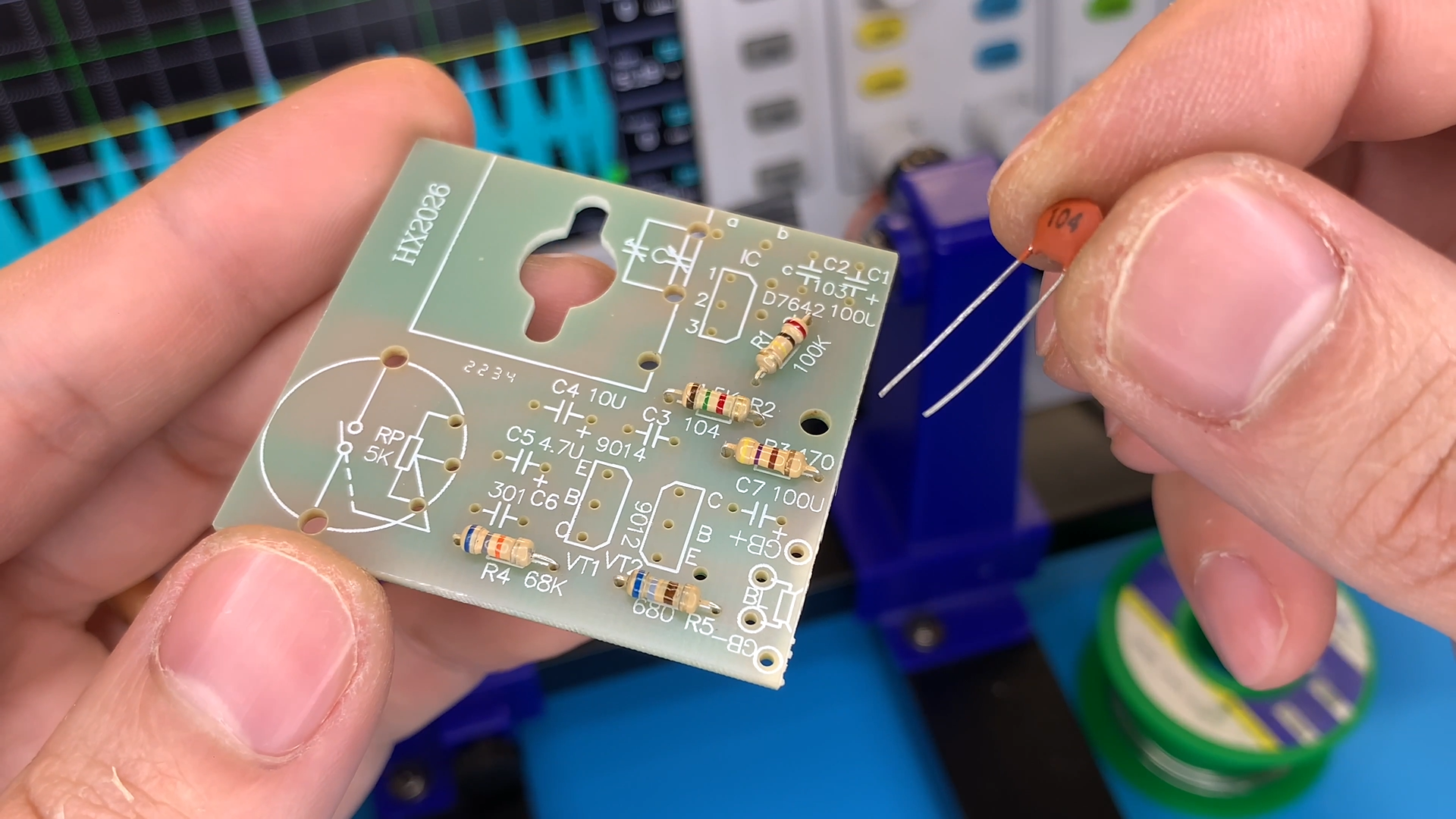
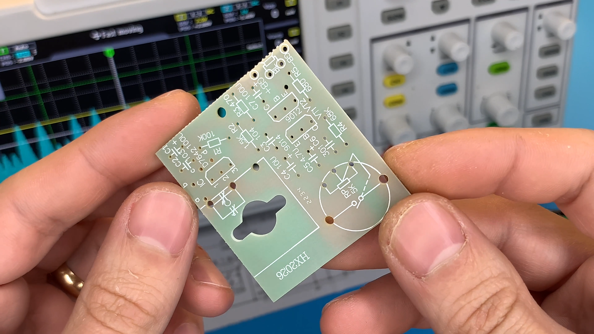
1. **Prepare Components**: Gather all the necessary components as per the list above.
Soldering
.png)
.png)
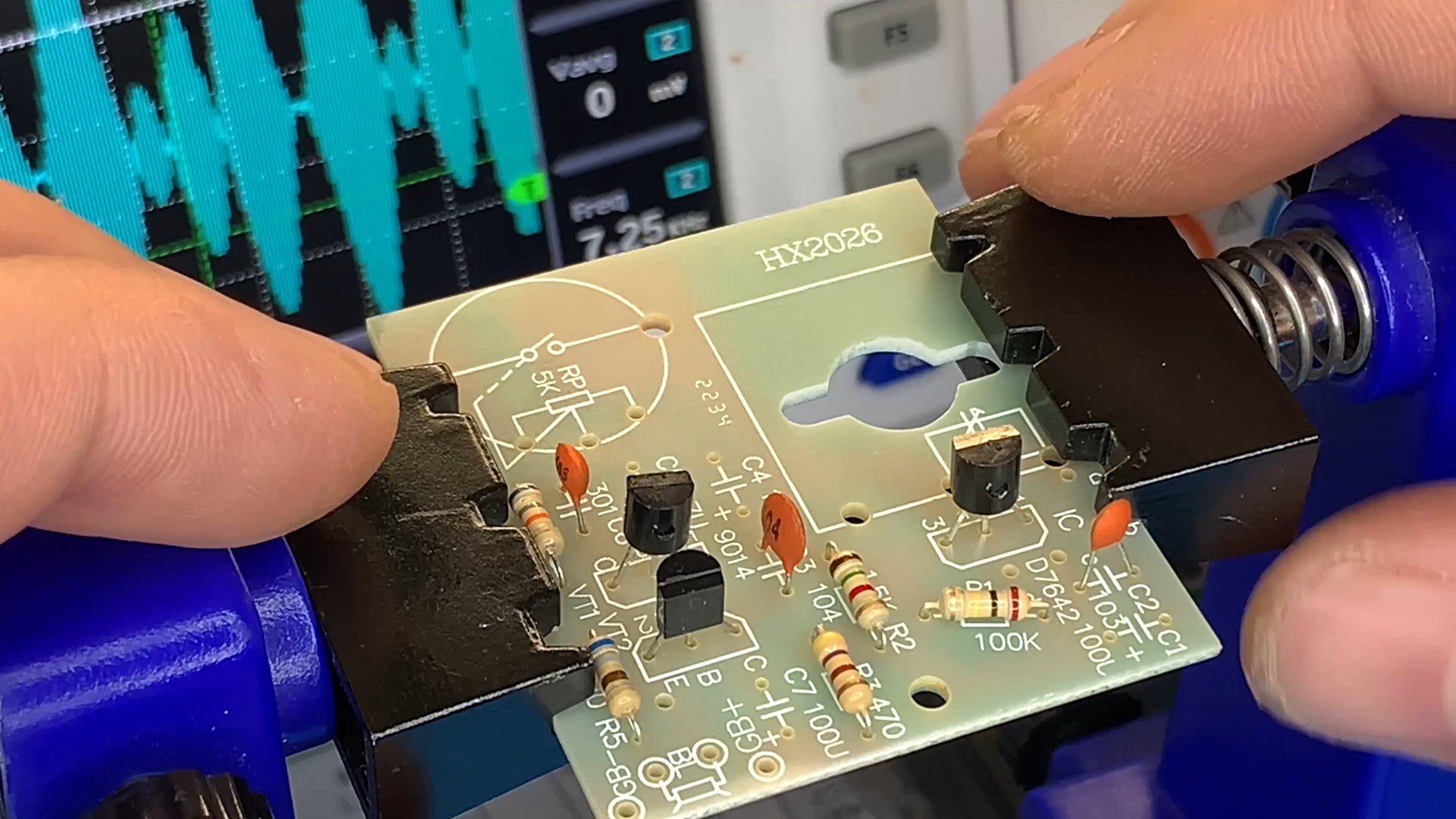
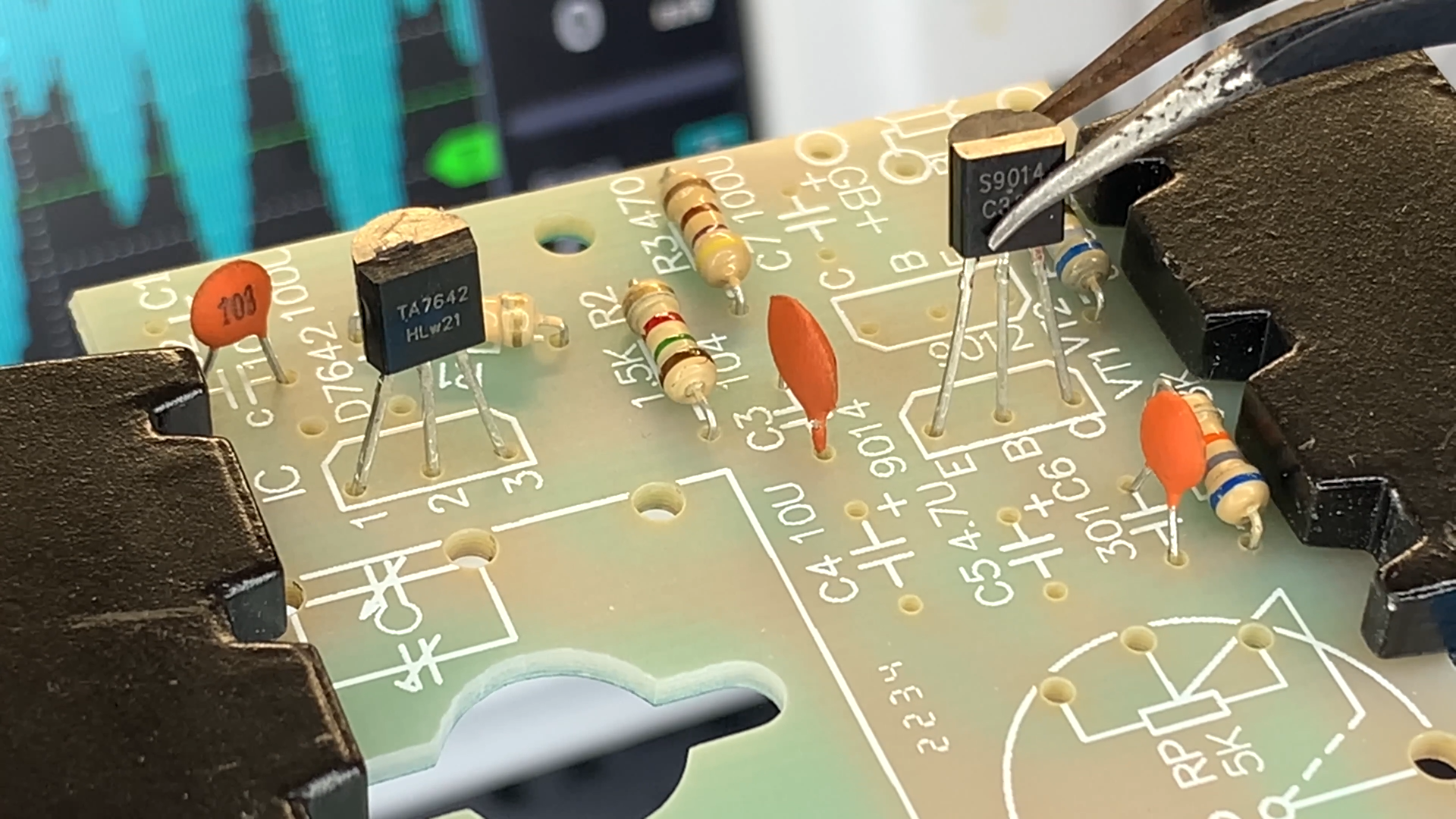
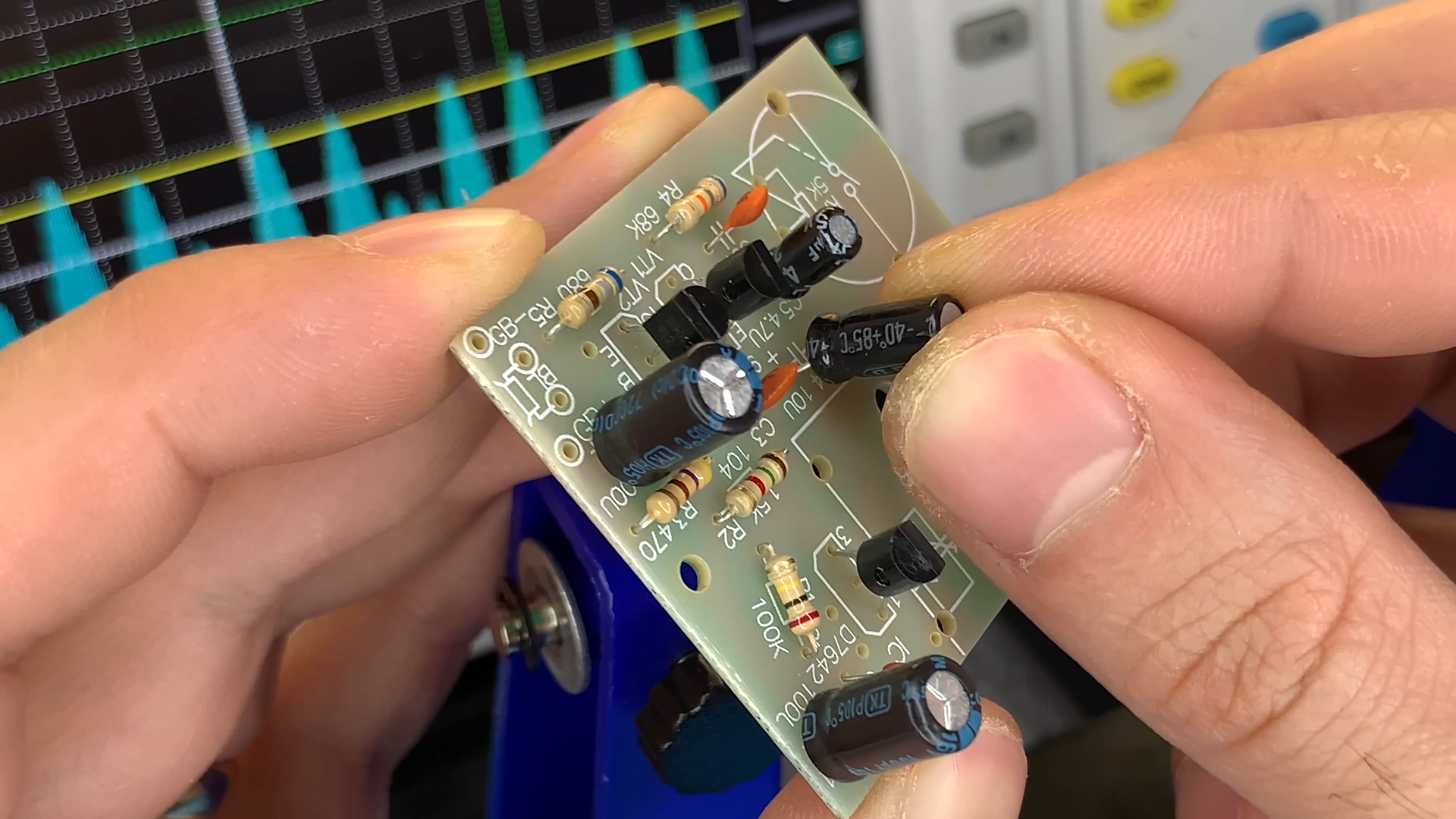
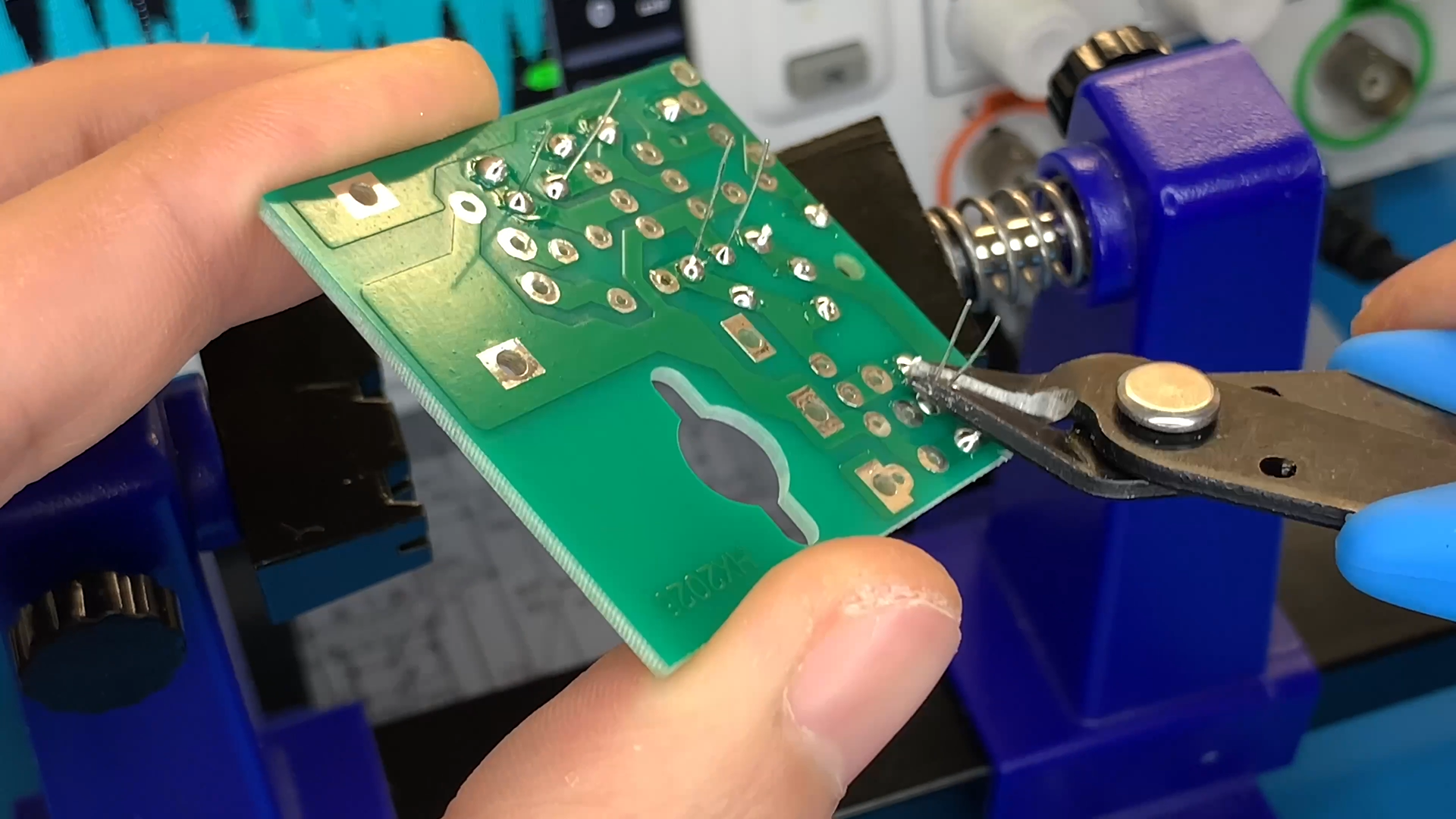
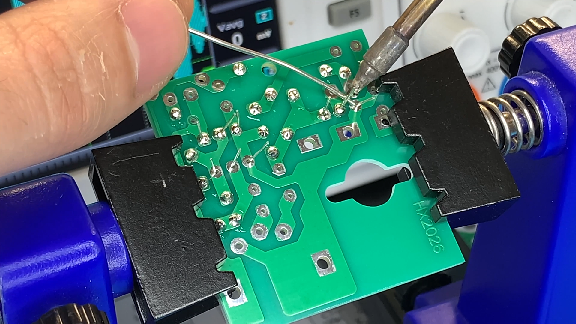
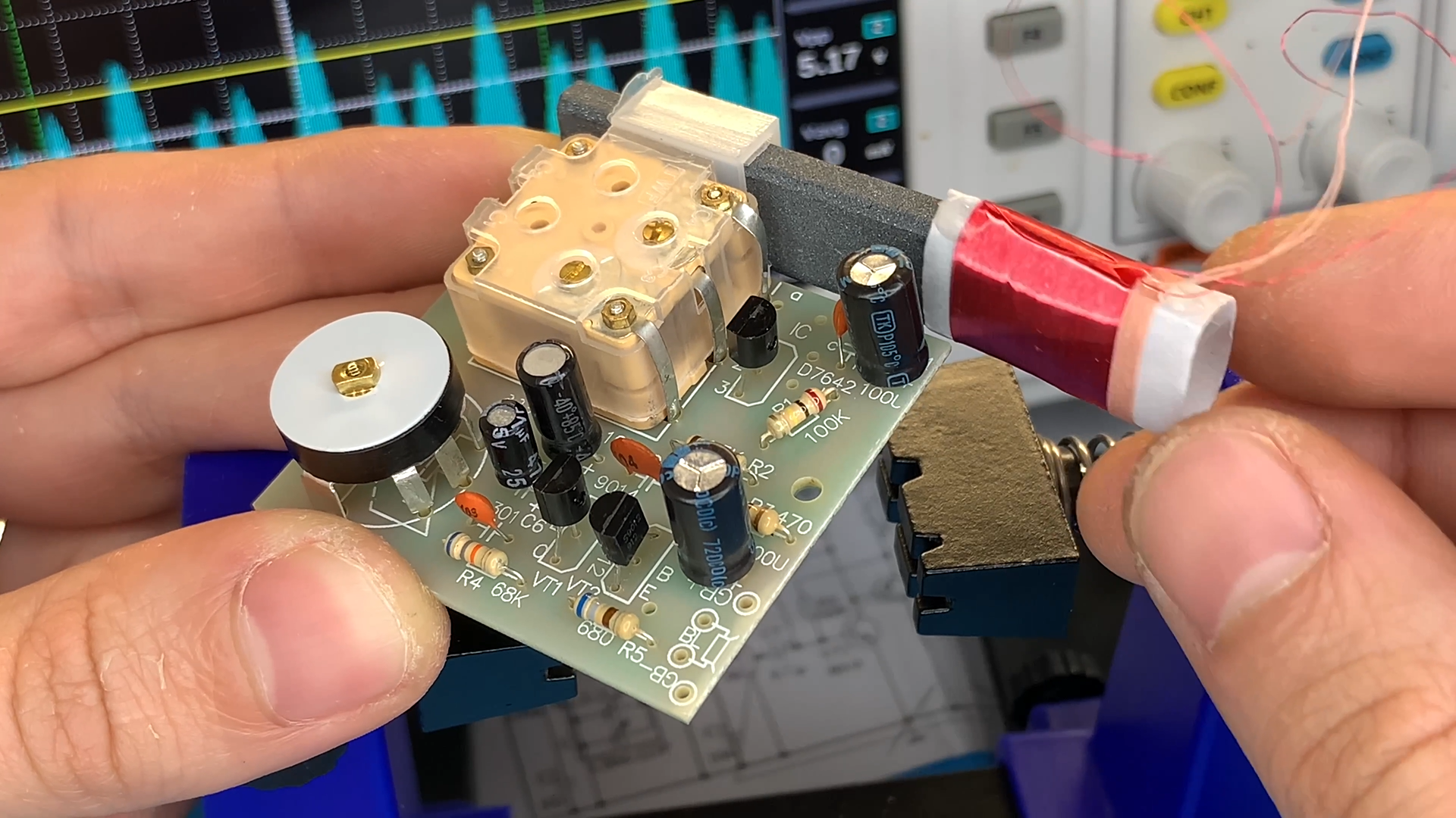
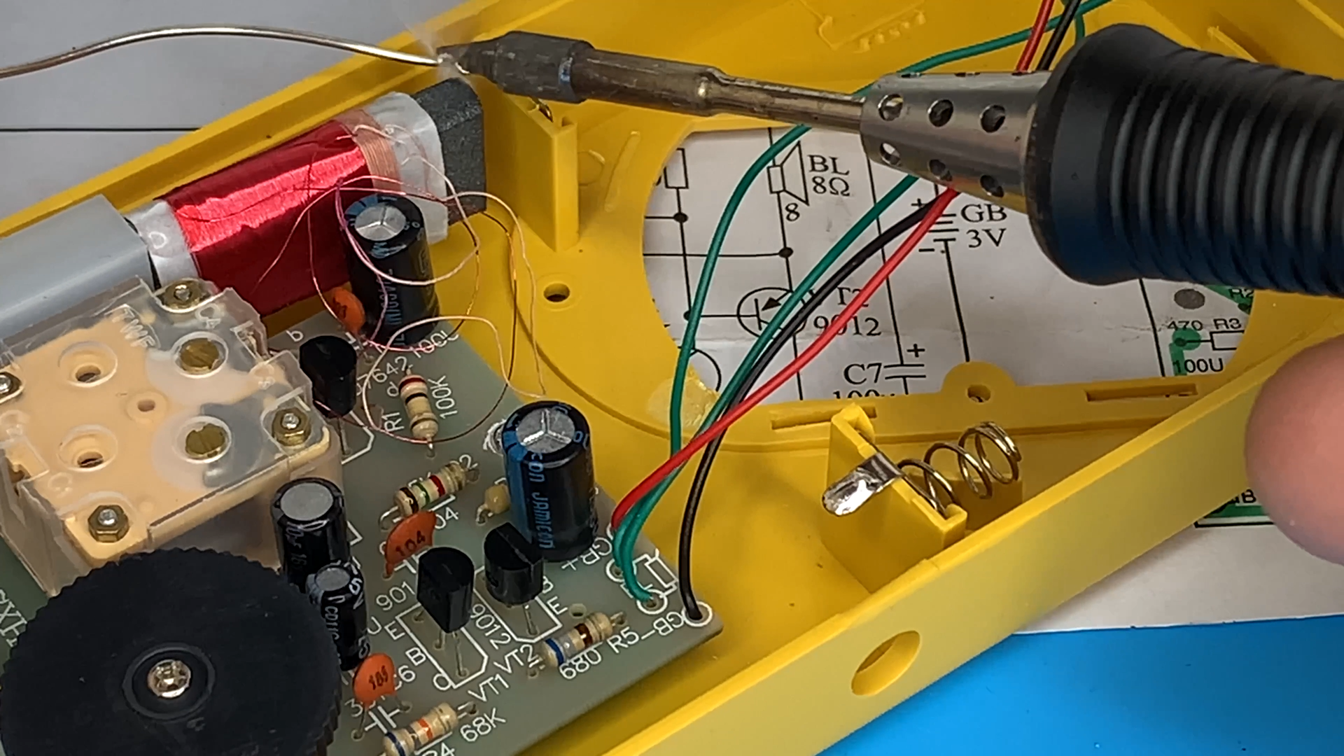
2. **Soldering**: Solder the components onto a perfboard or a PCB according to the schematic.
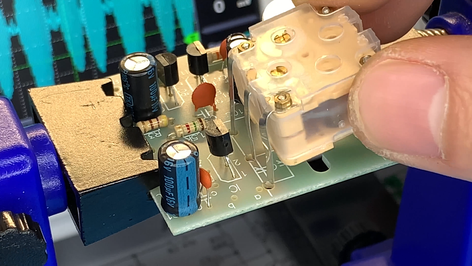
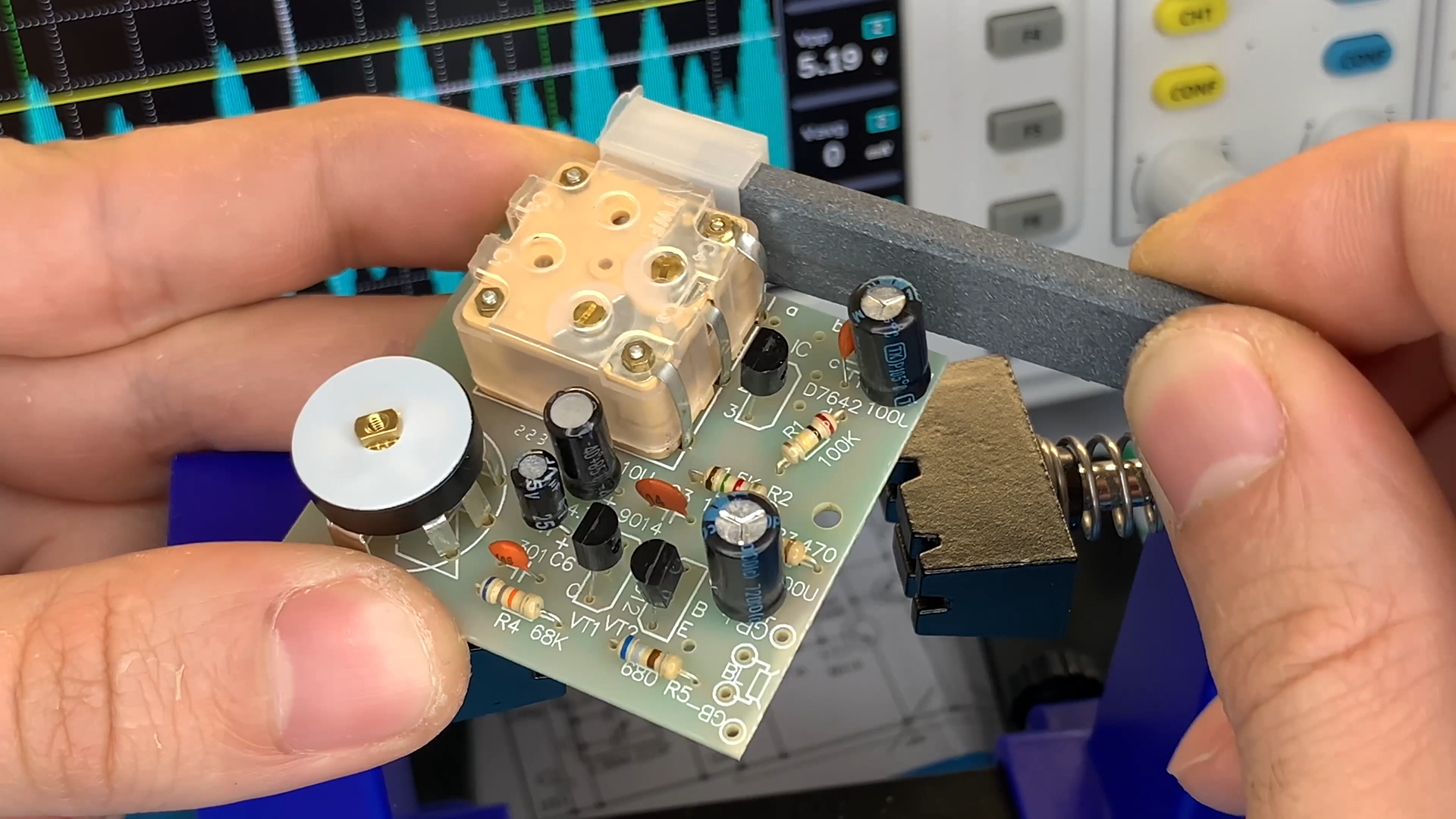
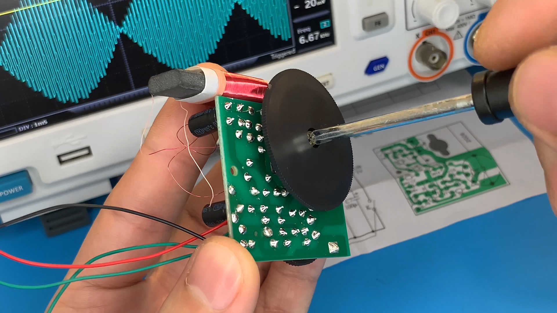
Tuning Capacitor
.png)
3. **Tuning Capacitor**: Connect the variable capacitor (tuning capacitor) to the circuit. This capacitor is used to tune different radio stations.
Antenna Connection
.png)
.png)
4. **Antenna Connection**: Connect the ferrite rod antenna to the point labeled "Antenna" in the schematic. You may need to experiment with the orientation and position of the antenna for best reception.
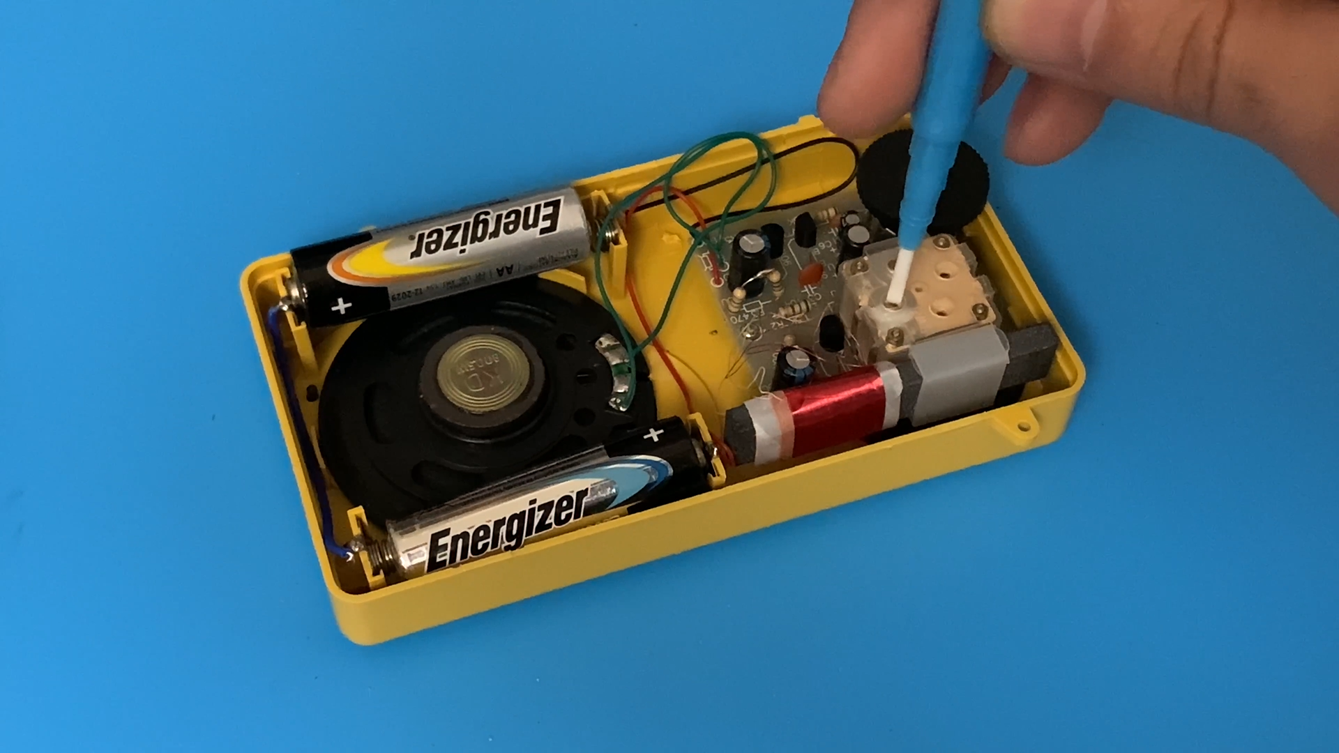
Connect Power
.png)
.png)
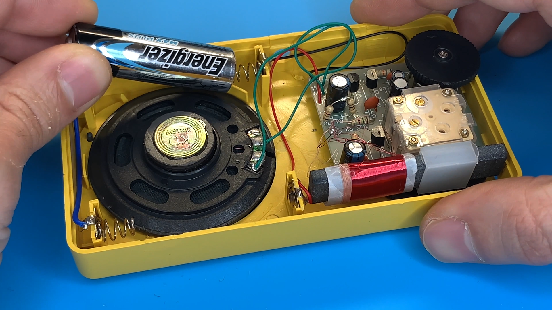
5. **Connect Power**: Connect the positive terminal of the battery or power supply to the positive rail, and the negative terminal to the ground.
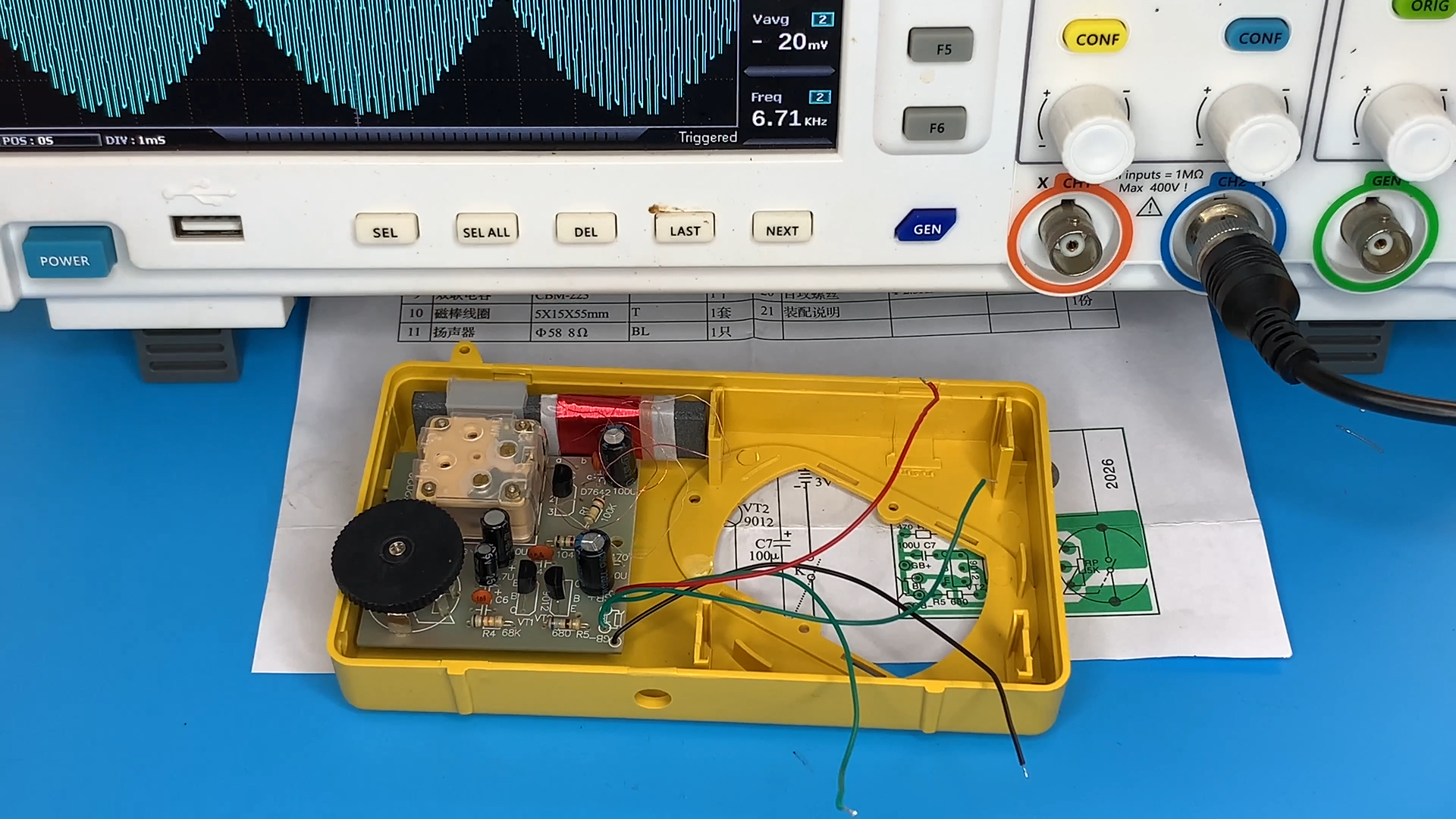
Testing
.png)
.png)
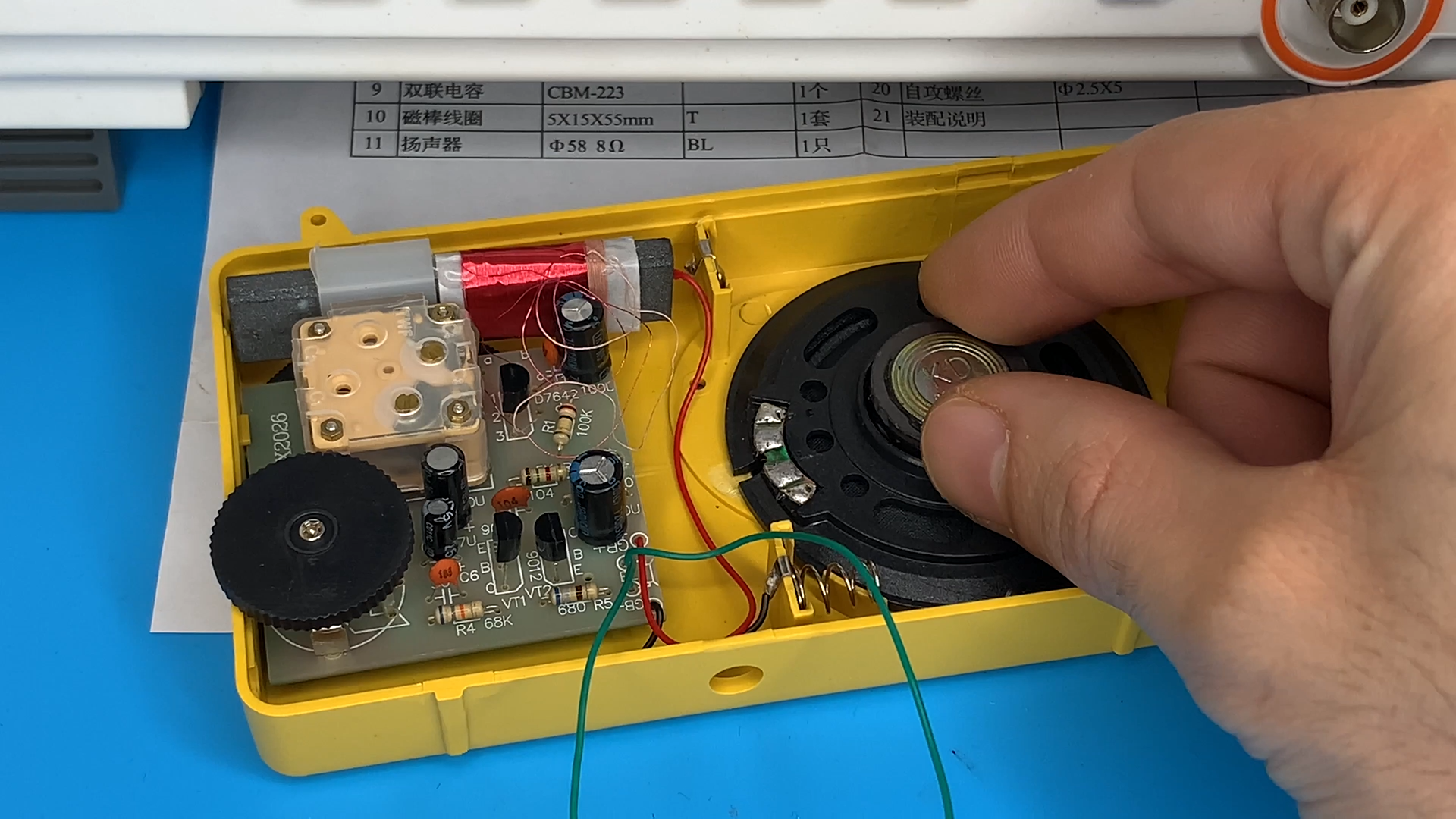
6. **Testing**: Connect a set of headphones or a small speaker to the output of the circuit. Turn on the power and carefully adjust the variable capacitor while listening for any radio stations.
Fine-tuning
.png)
.png)
7. **Fine-tuning**: Once you've found a station, adjust the variable resistor (potentiometer) if available to control the volume.
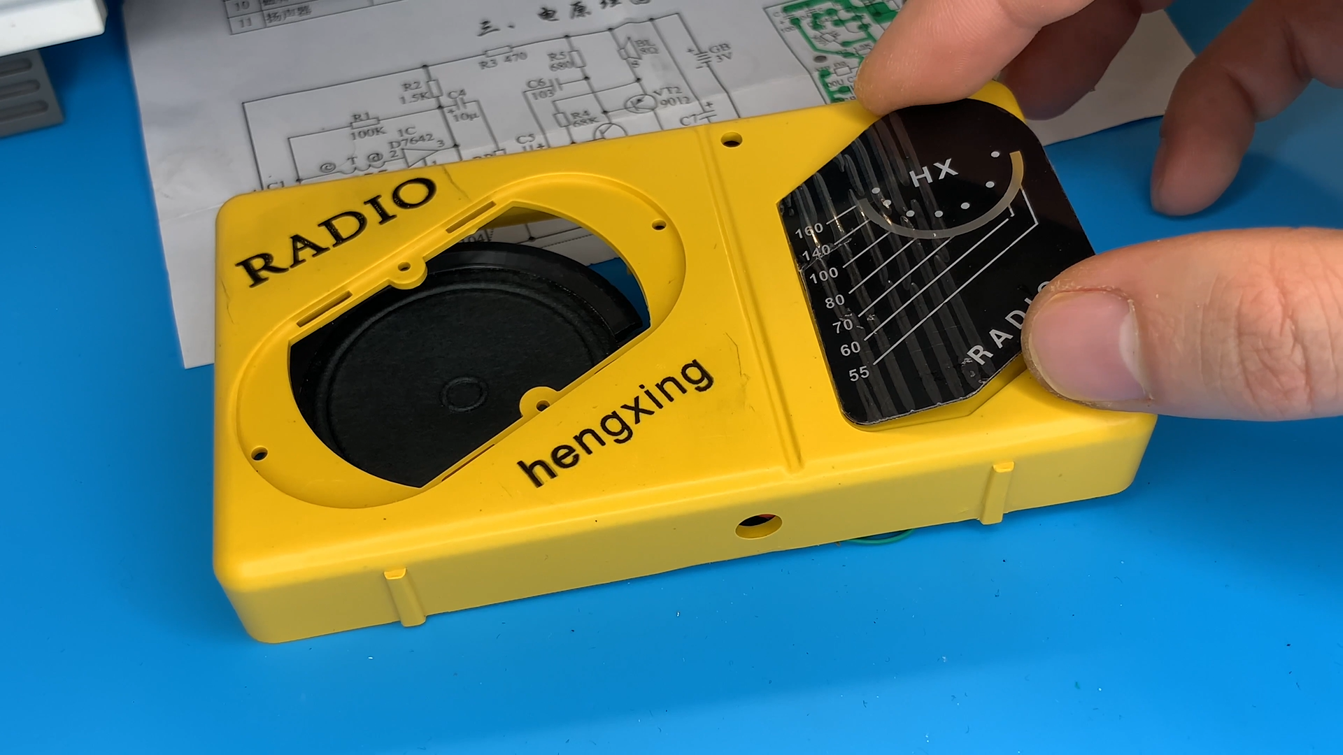
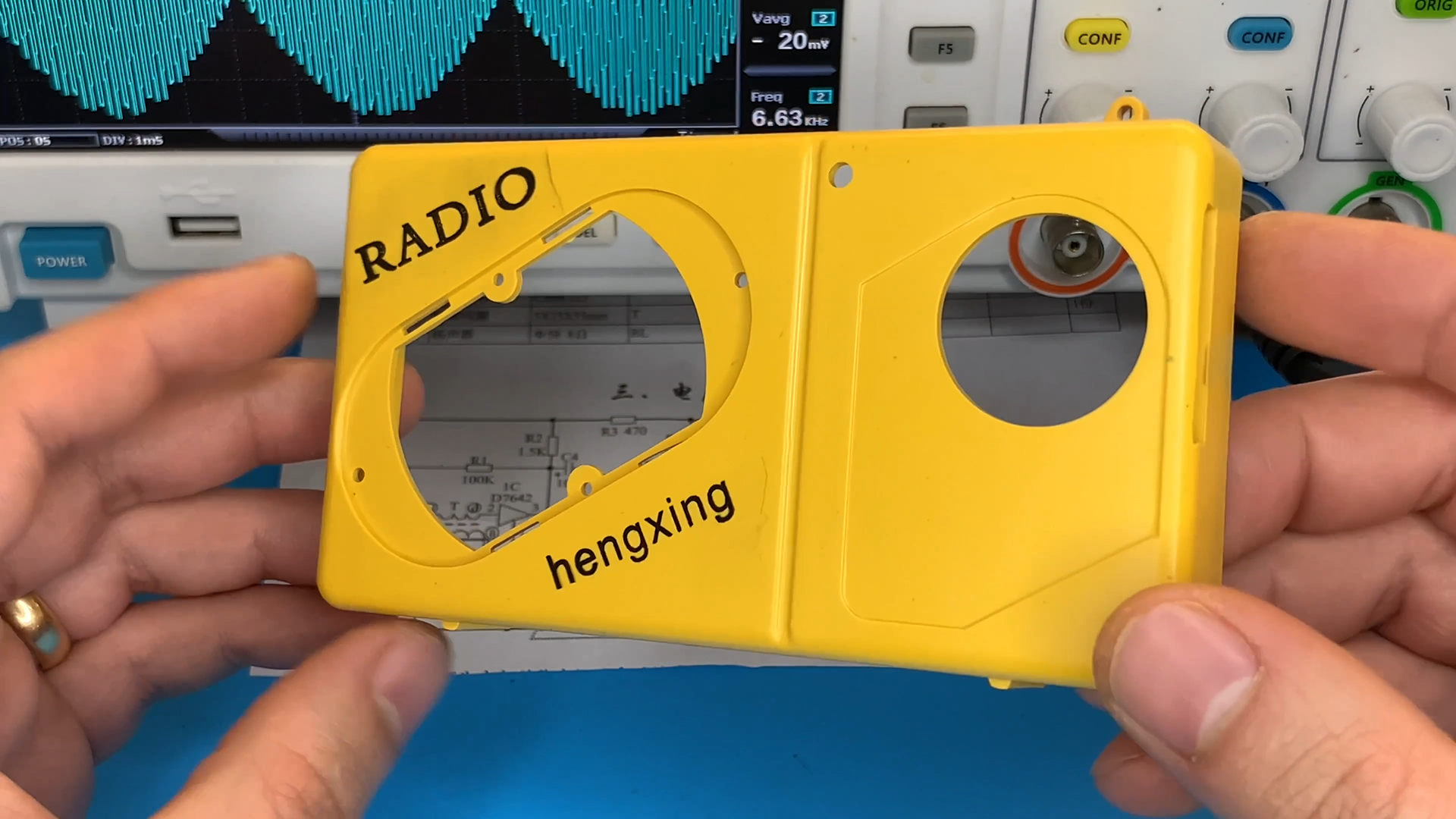
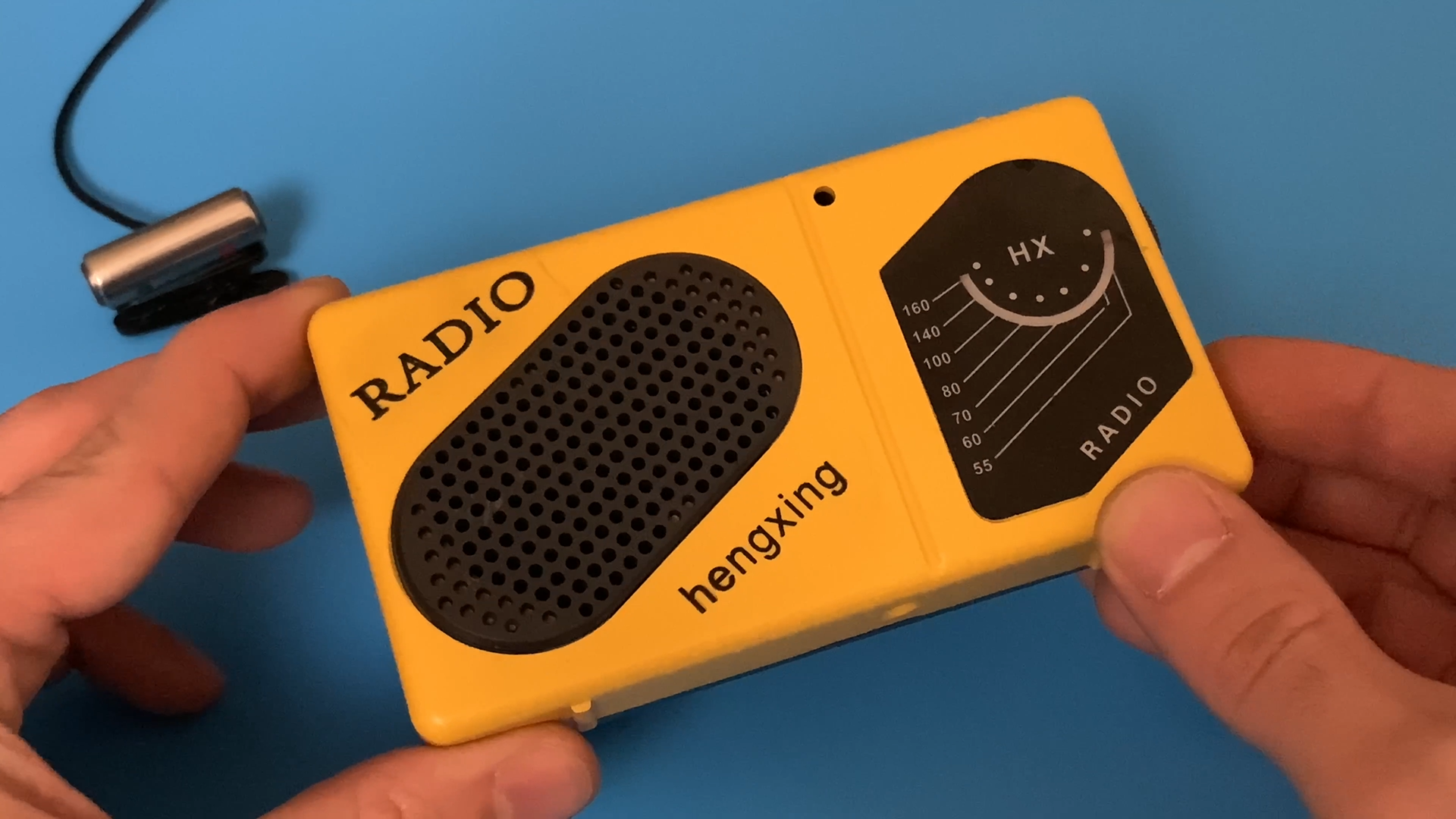
Enclosure
.png)
.png)
8. **Enclosure**: Once you're satisfied with the performance, consider enclosing the circuit in a suitable case to protect it and make it more portable.
Experimentation
.png)