How to Make PIR Motion Sensor Light at Home
by VinayakJaid in Circuits > Arduino
2144 Views, 3 Favorites, 0 Comments
How to Make PIR Motion Sensor Light at Home
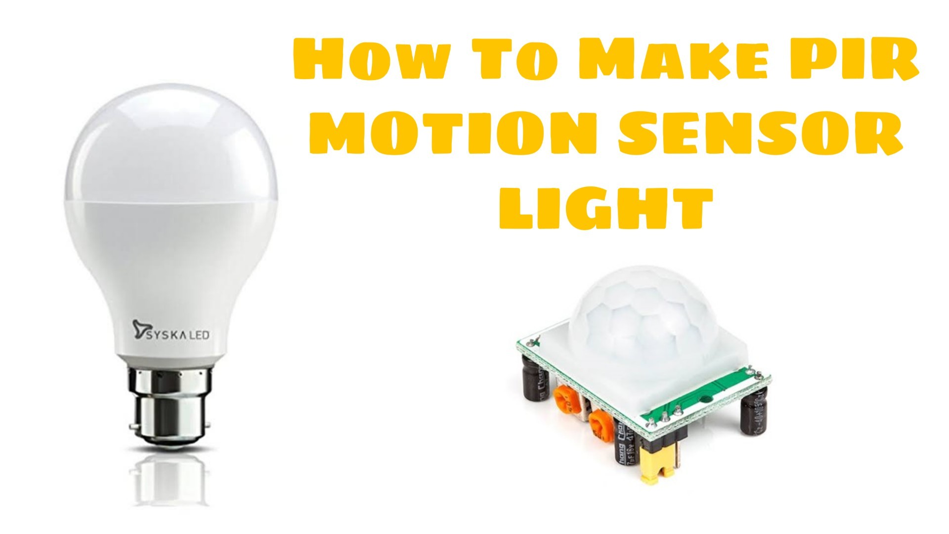
In this video i have shown how to make a pir motion sensor light at home.
You can watch my video on youtube.
Please subscribe If you like my video and Help me to Grow.
https://youtu.be/is7KYNHBSp8
You can watch my video on youtube.
Please subscribe If you like my video and Help me to Grow.
https://youtu.be/is7KYNHBSp8
Gather the Parts
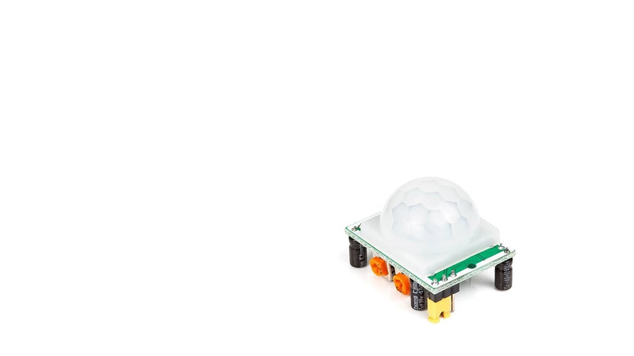
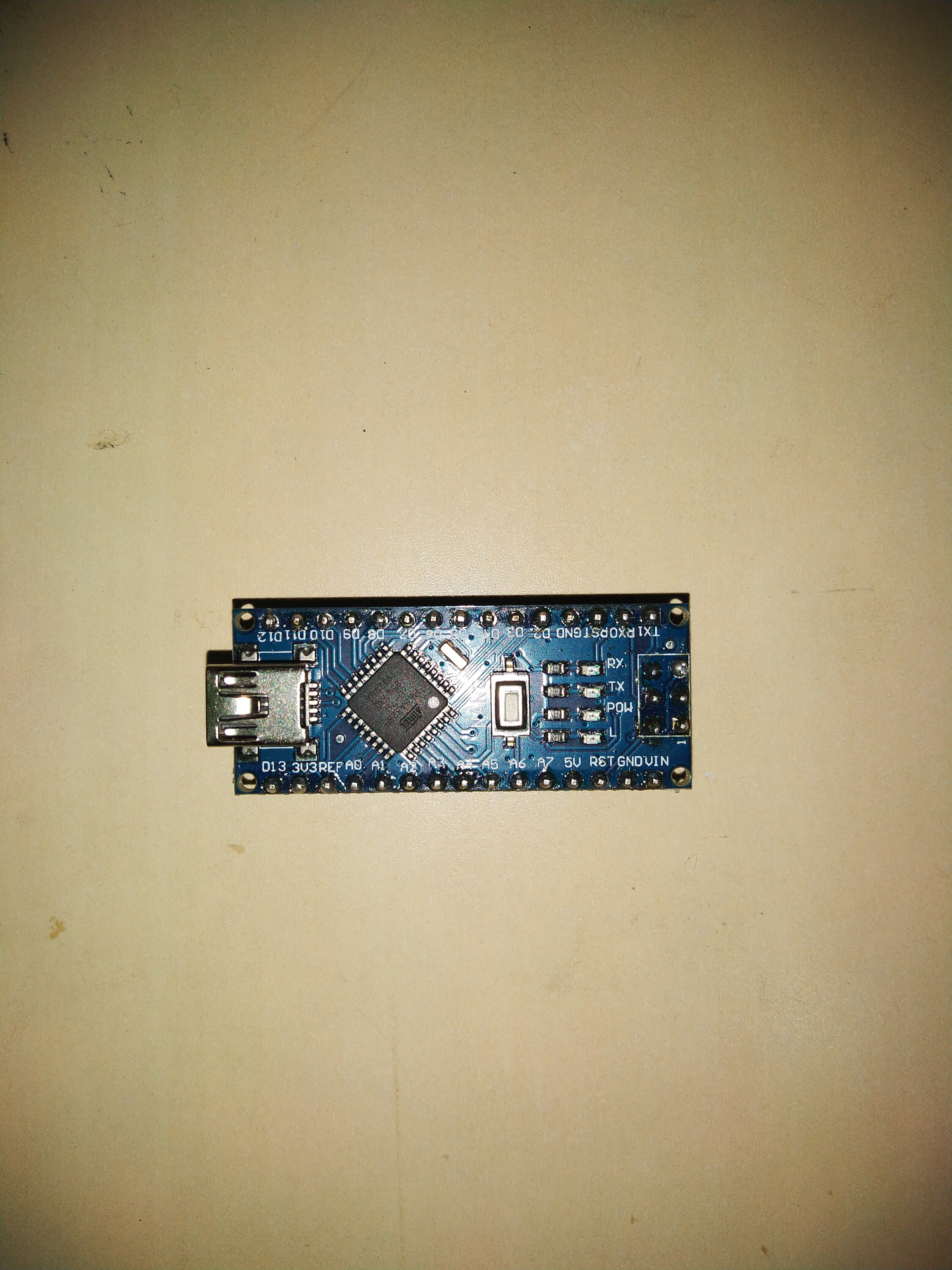
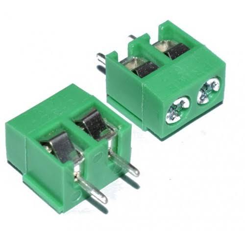
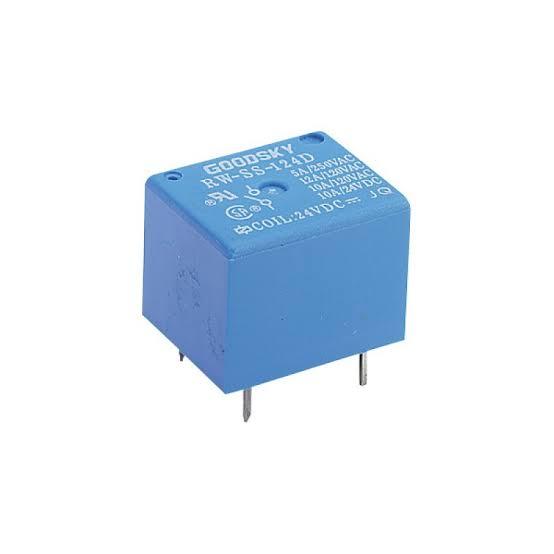
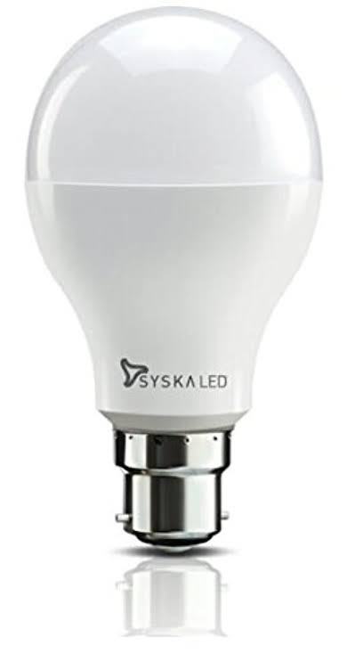
You required -
Arduino uno / nano x 1
PIR motion sensor x 1
5V relay x 1
PBT connectors x 1
Pcb board x 3
bulb holder
A bulb
Solder wire and solder
And AC male connectors and few wires
Arduino uno / nano x 1
PIR motion sensor x 1
5V relay x 1
PBT connectors x 1
Pcb board x 3
bulb holder
A bulb
Solder wire and solder
And AC male connectors and few wires
Connect PIR Sensor
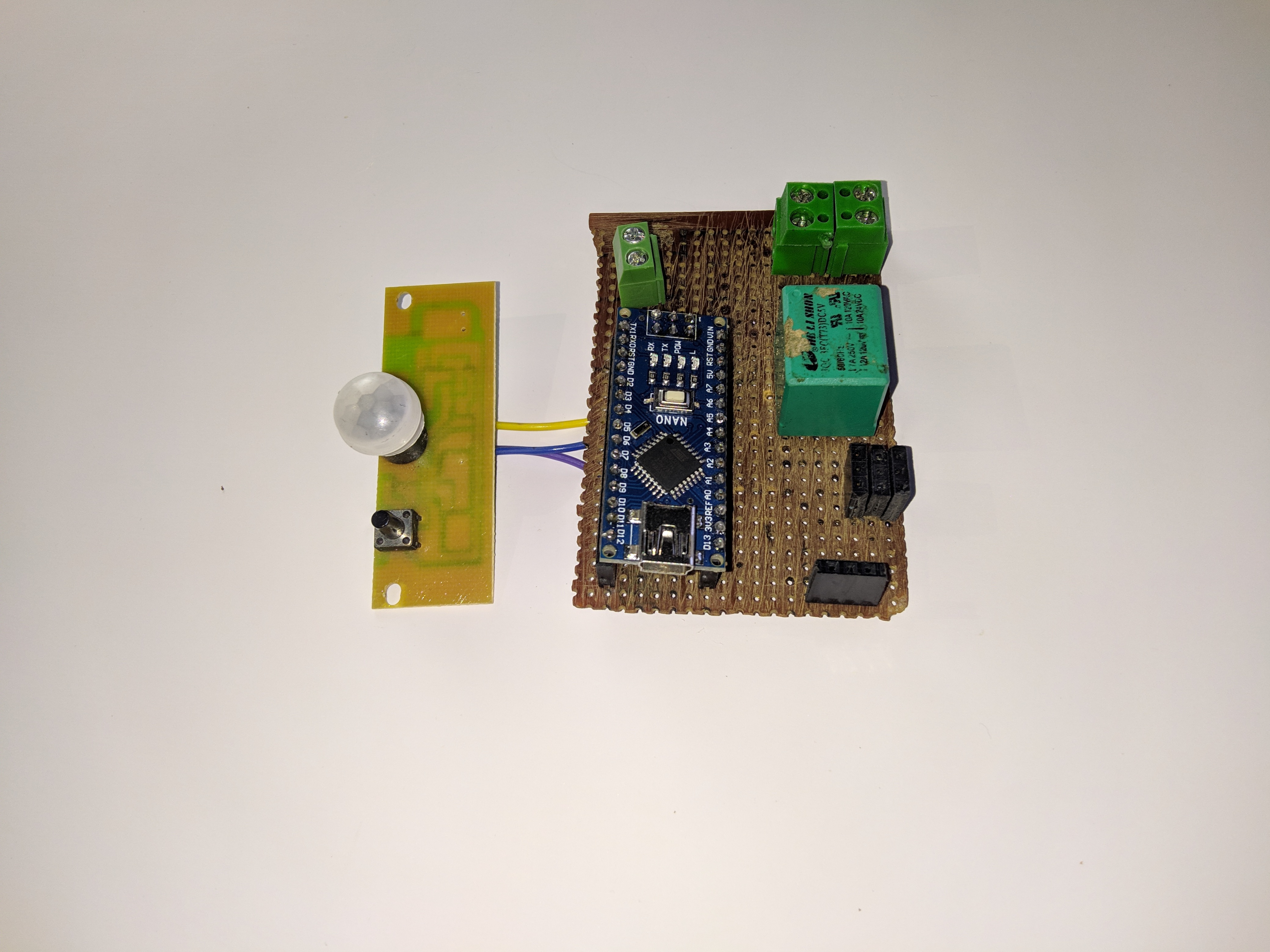
Connect pir sensor V in to 5v port of ardhino.
Connect pir sensor GND pin to GND. Pin of arduino.
Connect Vout of Pir sensor pin to D8 of arduino.
Use mount for arduino so you wont damage it while soldering.
Connect pir sensor GND pin to GND. Pin of arduino.
Connect Vout of Pir sensor pin to D8 of arduino.
Use mount for arduino so you wont damage it while soldering.
Connect Relay
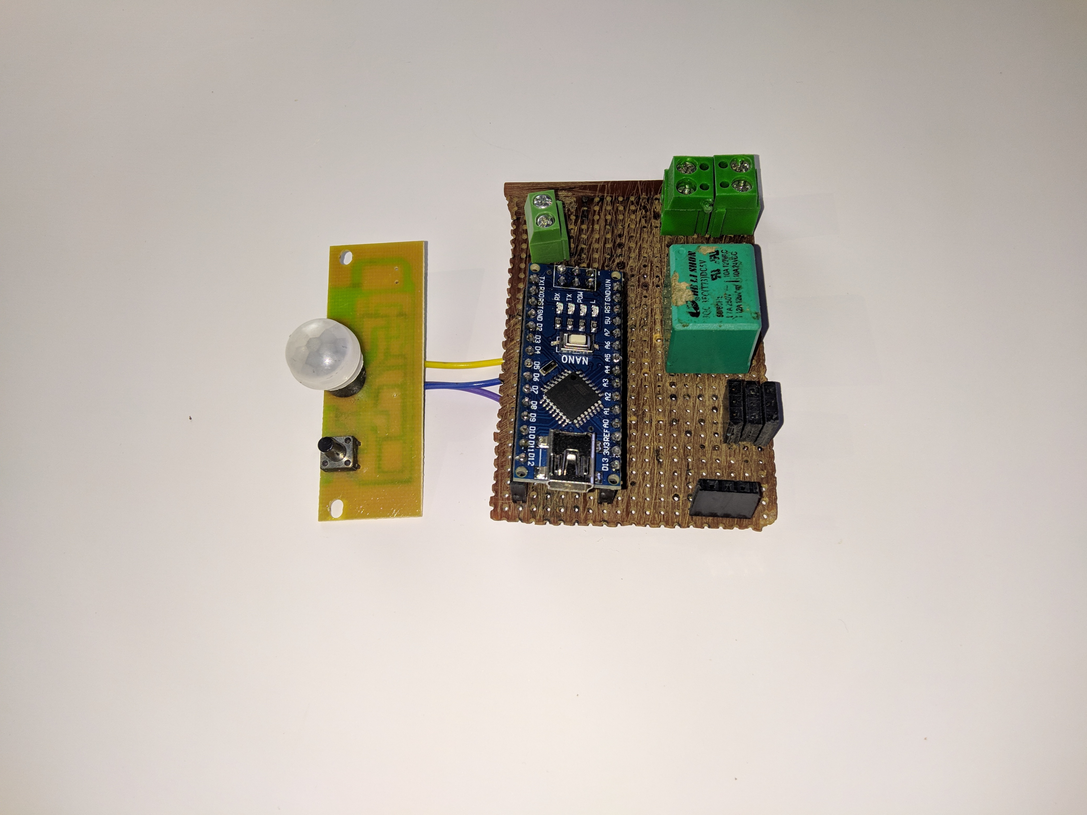
Connect coil pins of relay to the GND pin of arduino and D9 pin.
Since whenever PIR sensor detects any movement, sensor will give output to the arduino.
Then arduino will send signal to relay to actuate.
Since whenever PIR sensor detects any movement, sensor will give output to the arduino.
Then arduino will send signal to relay to actuate.
Connect PBT Connectors
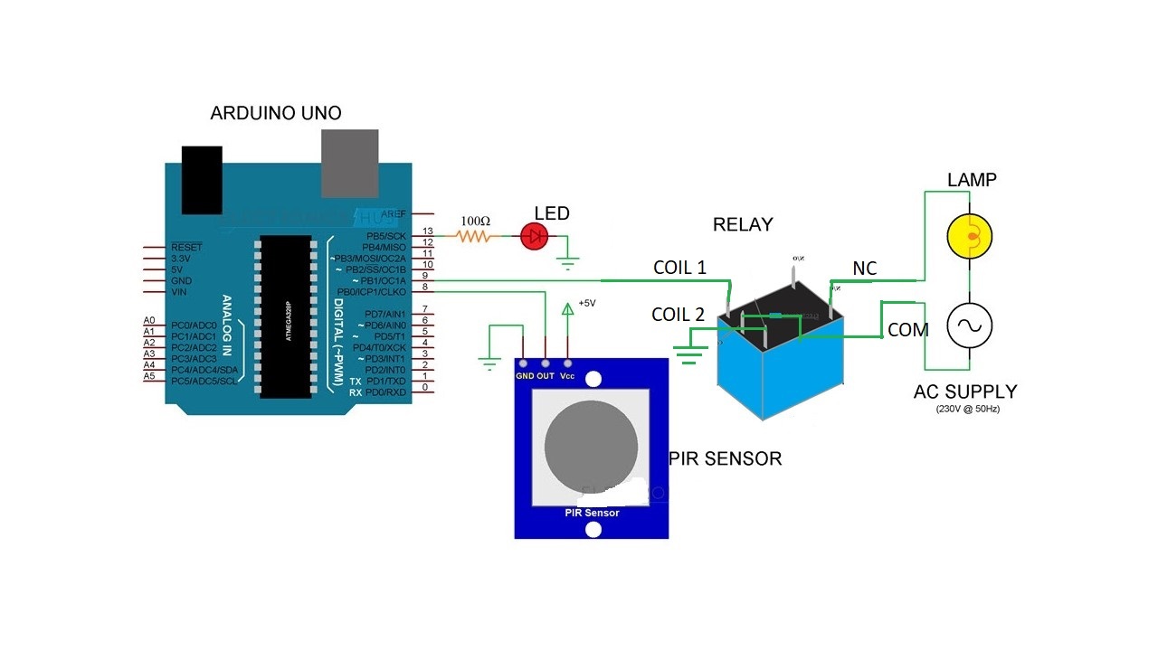
Mount two pbt connectors and solder them.
Solder one pin of both pbt pins.
Solder One of the pbt connector remain pin to common pin of relay.
And another pbt connector to NC Pin of relay.
Solder 3rd pbt connector near arduino and its terminal to Vin and GND of arduino.
So you can power arduino from 5v-12v.
If you dont understand How to connect them watch my video and you can refer circuit diagram also.
Connect AC Wires and Bulb
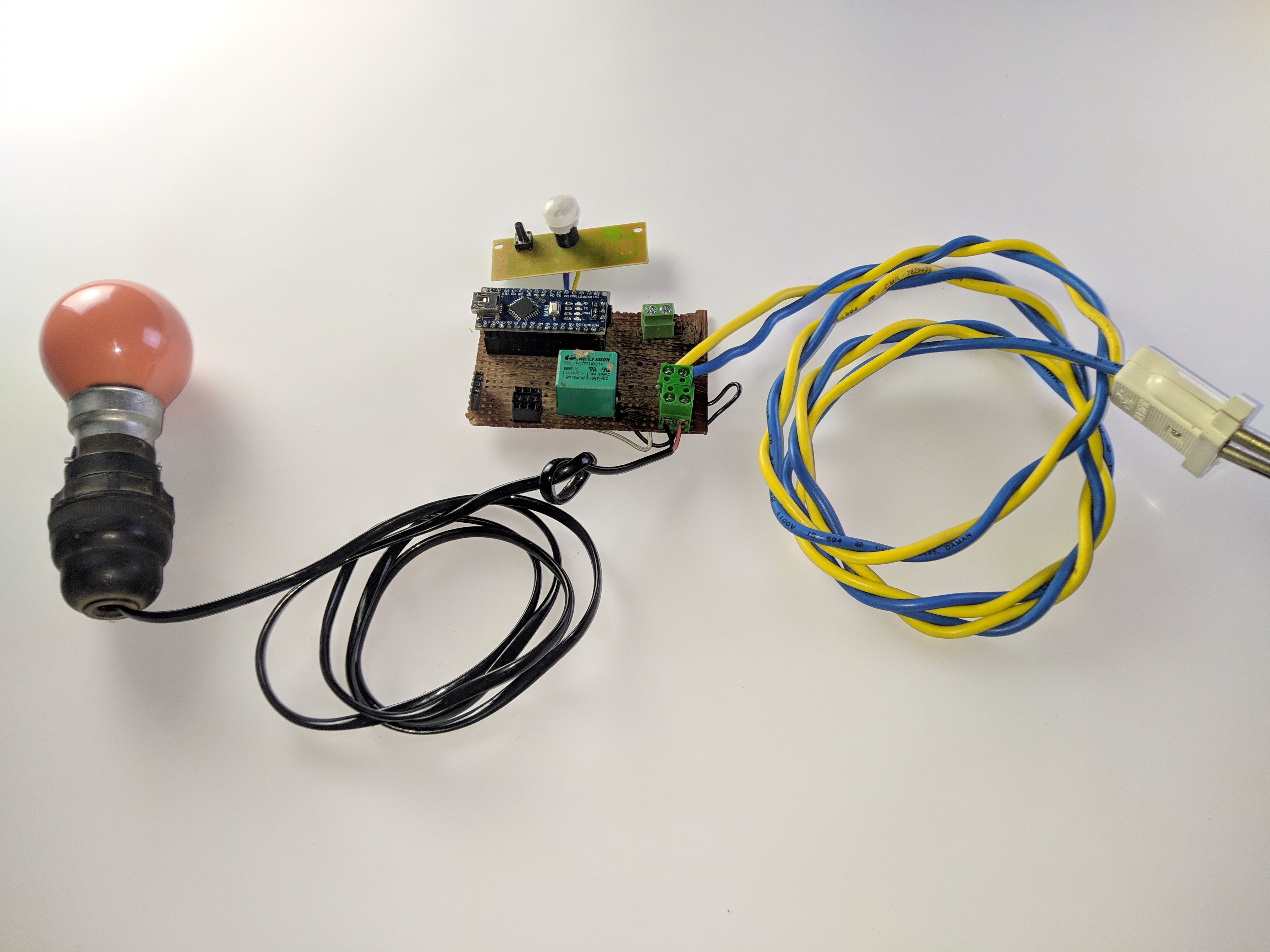
Connect bulb holder wire to any of the pbt connector ( except one which is for powering arduino).
Connect AC Connection wire to remain pbt terminals.
You can use external power supply to power arduino through the pbt connectors.
Please dont confuse between the connections .
Connect AC Connection wire to remain pbt terminals.
You can use external power supply to power arduino through the pbt connectors.
Please dont confuse between the connections .
Upload the Code
Now upload the code in the arduino .
Make sure you downloaded drivers in computer and choose right board and right port.
Code Download link is here -
https://youtu.be/is7KYNHBSp8
Make sure you downloaded drivers in computer and choose right board and right port.
Code Download link is here -
https://youtu.be/is7KYNHBSp8
Now Its Time to Test
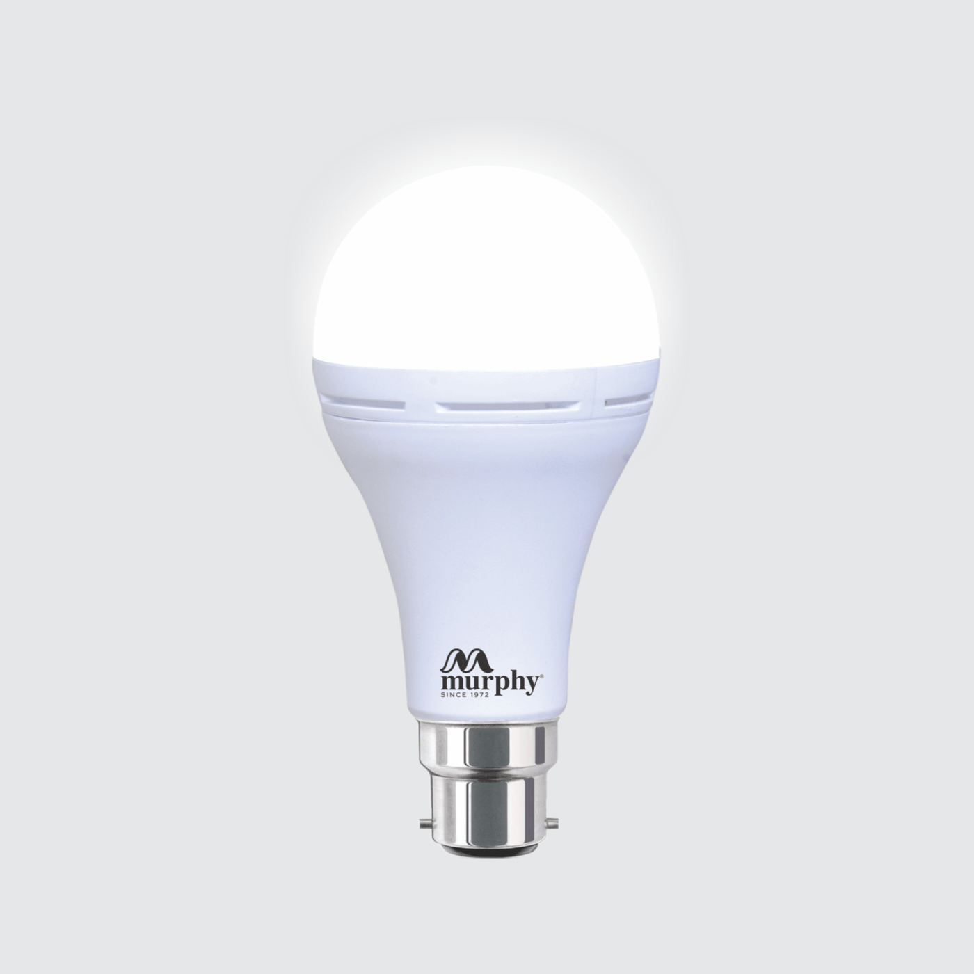
Turn on the arduino and supply ac current through ac wires.
And make movement infront of sensor, so bulb will glow and remove you hand and go away from it so after sometime it will be dimmed.
And make movement infront of sensor, so bulb will glow and remove you hand and go away from it so after sometime it will be dimmed.