How to Make Mini CNC Machine
by shubhamsuresh in Circuits > Arduino
43567 Views, 354 Favorites, 0 Comments
How to Make Mini CNC Machine
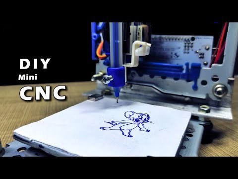
Hello all hope you are doing good. I'm here with another very cool project which you can build using some scrap/ used parts of the computer. In this Instructables I'm going to show you how you can make a mini CNC Machine at home from the old DVD Writers of the Computer and the Arduino UNO. by using this CNC machine you can draw logo and can write text also. For better understanding, you can refer this video.
Components Used
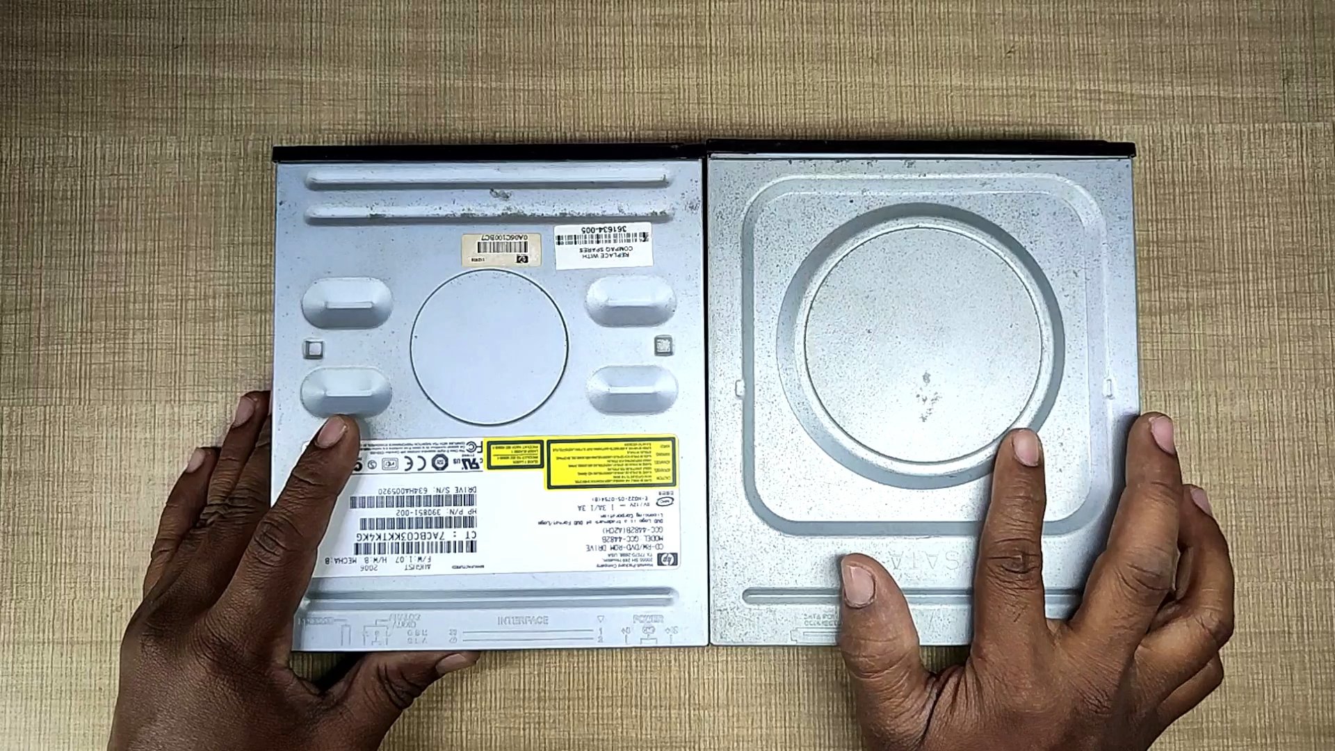
1- Old/ Used DVD Writers 2X ___________ (you can get these from any computer repairing/servicing shop)
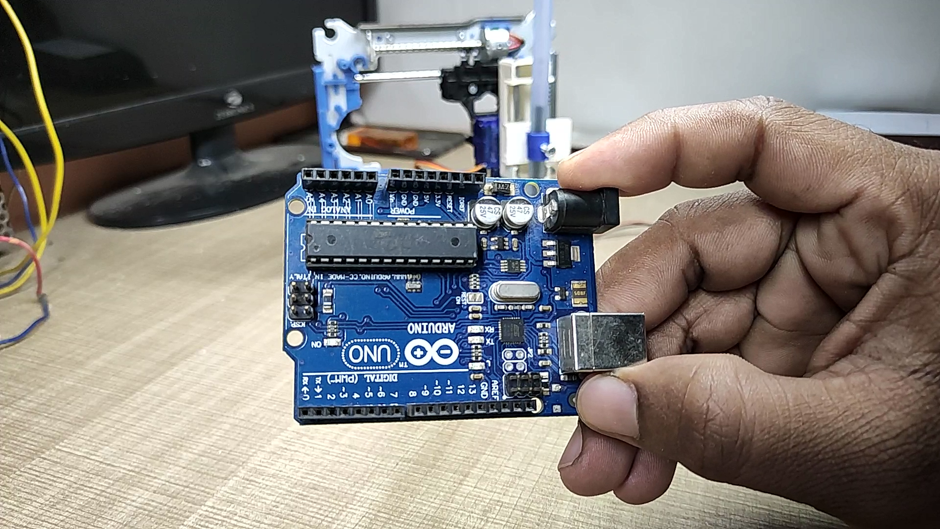
2- Arduino UNO 1X ___________________ USA / INDIA
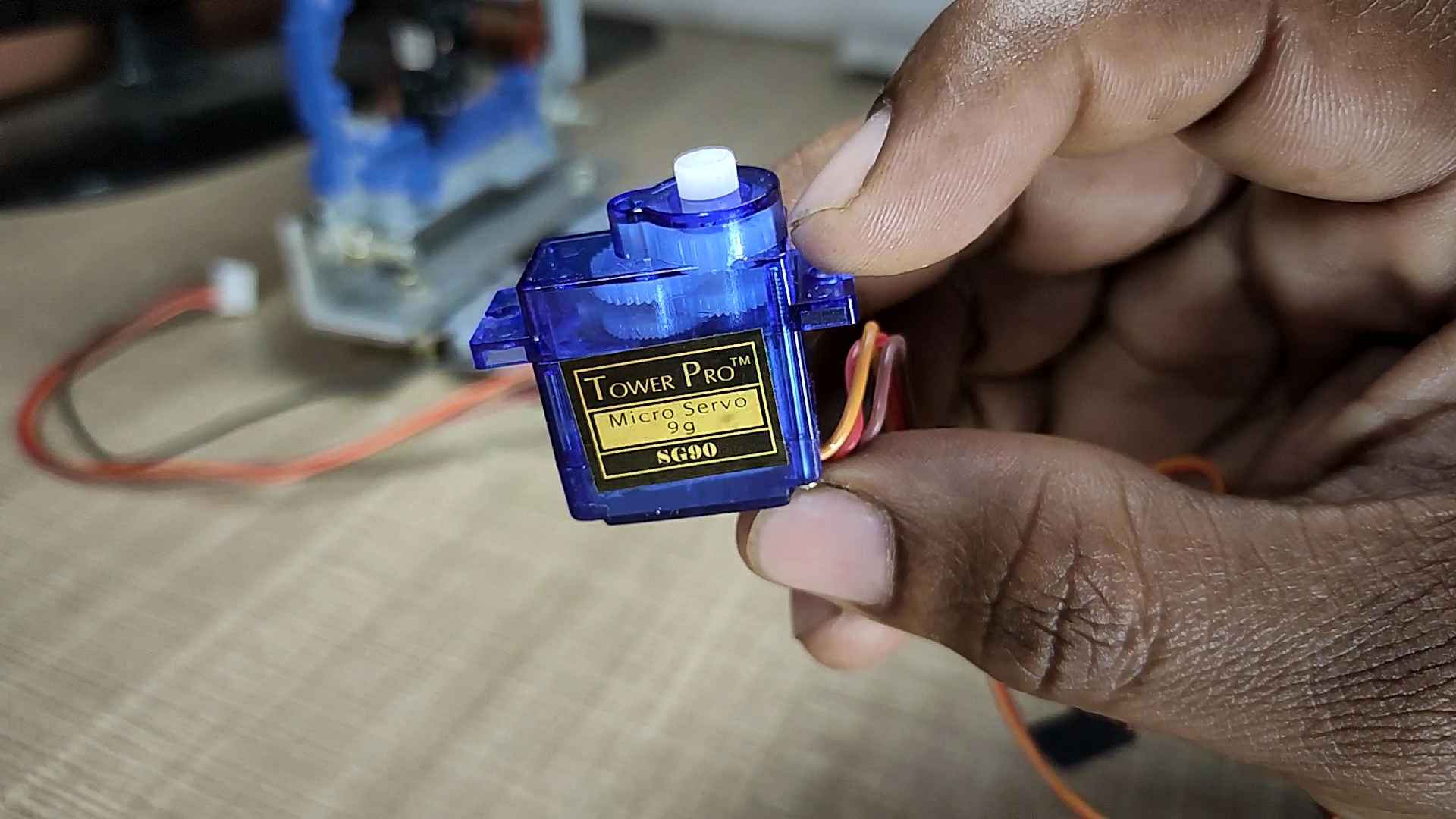
3- Servo Motor 1X ____________________ USA / INDIA
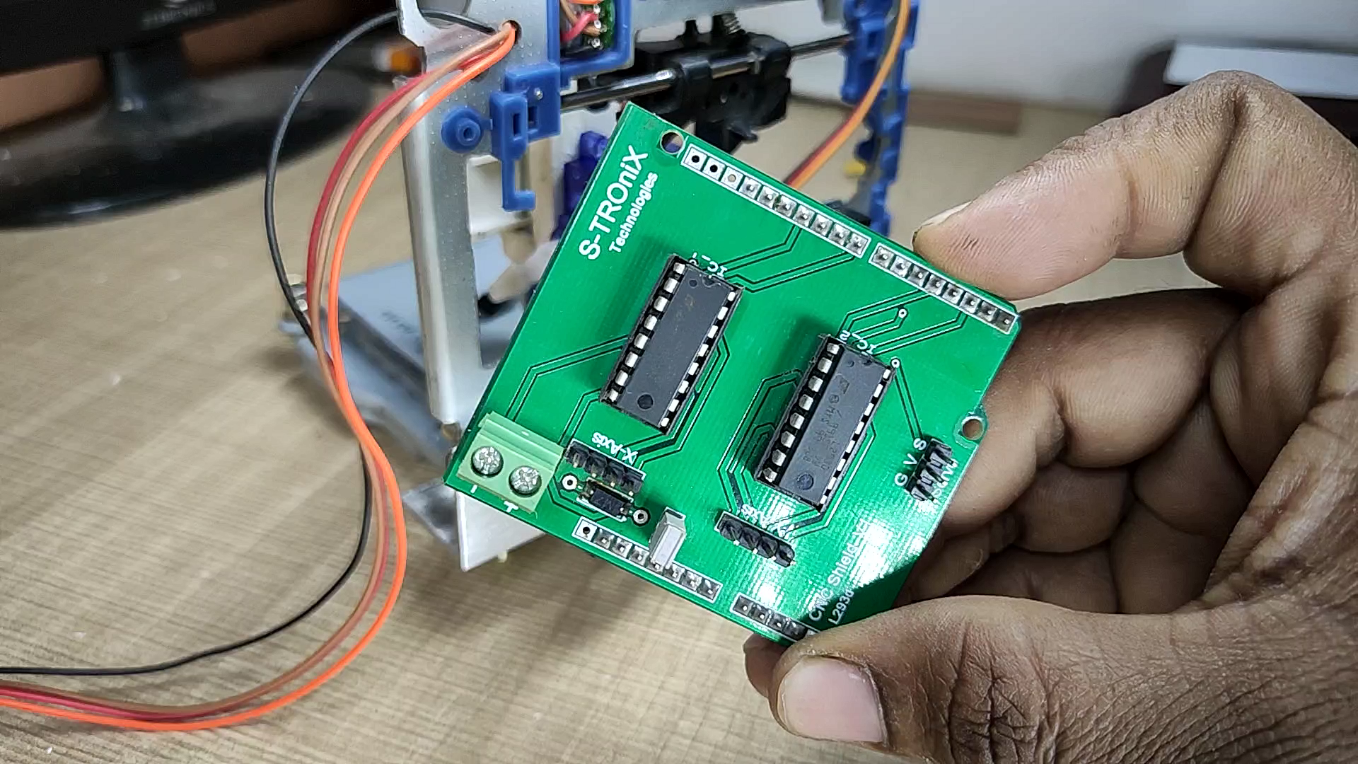
4- CNC Shield V1 (PCB)________________ PCBWay.com
5- L293D IC 2X _______________________ USA / INDIA
6- A piece of Aluminium ________________ From local store
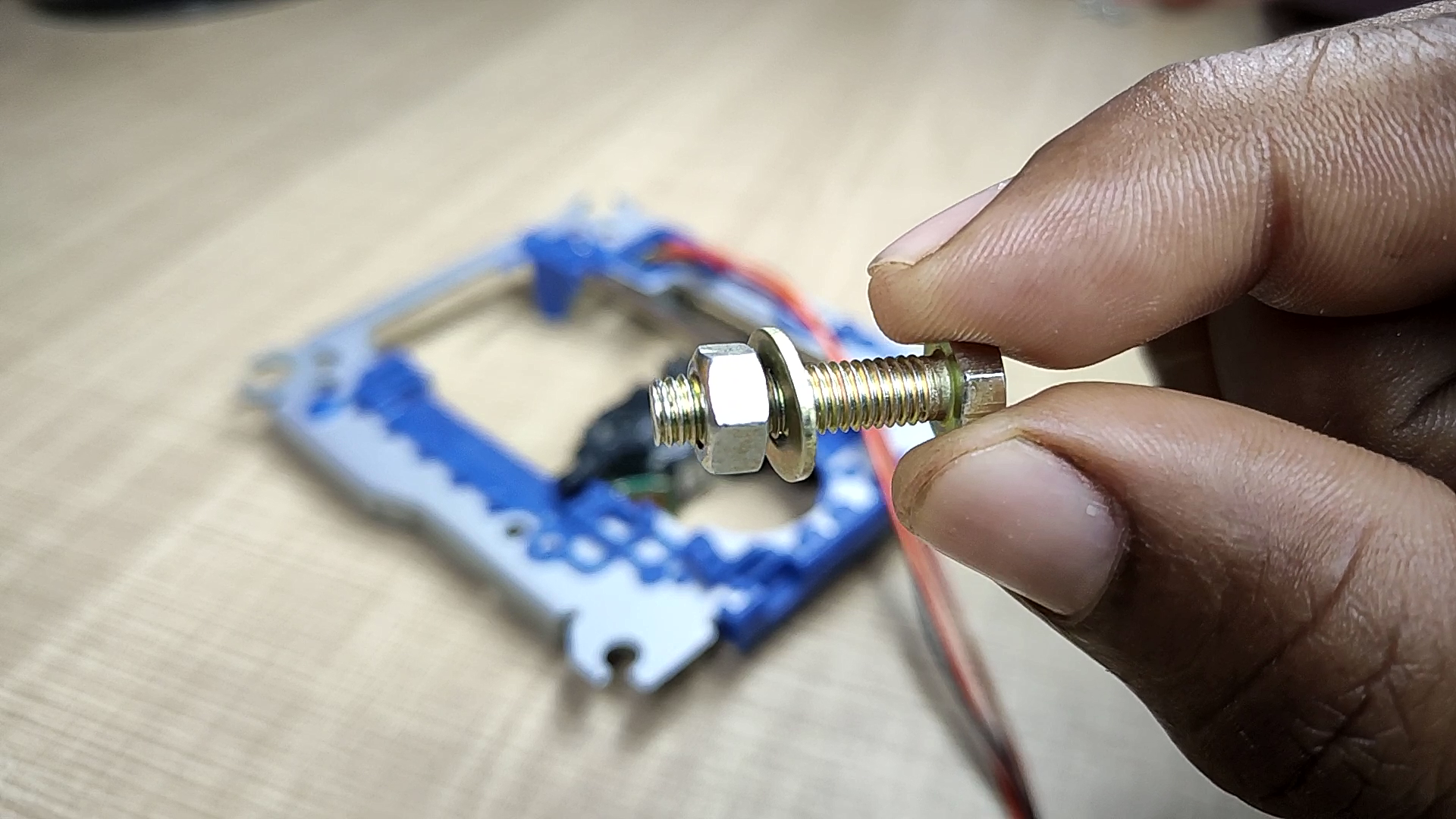
7- M5x25mm Nuts & Bolts ______________ From local store
8- flaxible Wires_______________________ From local store
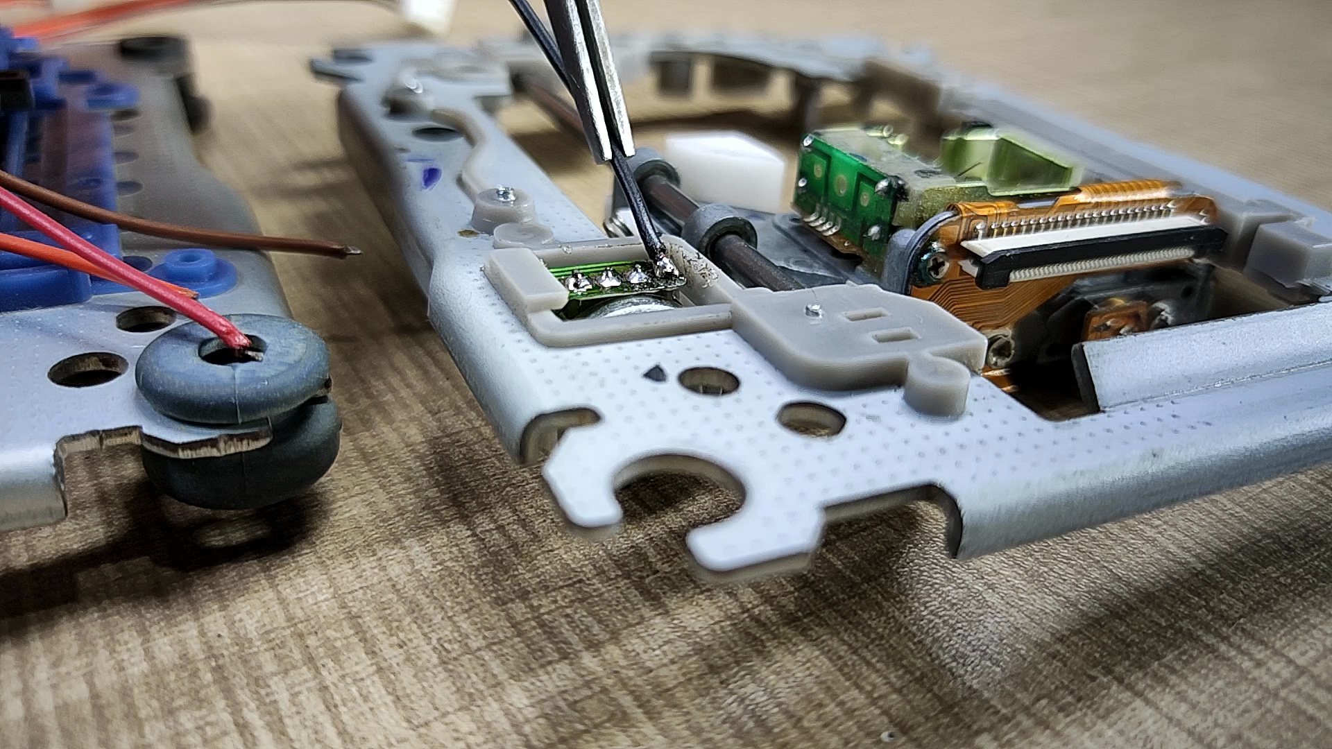
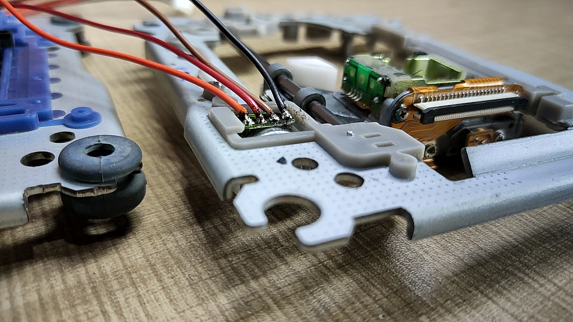
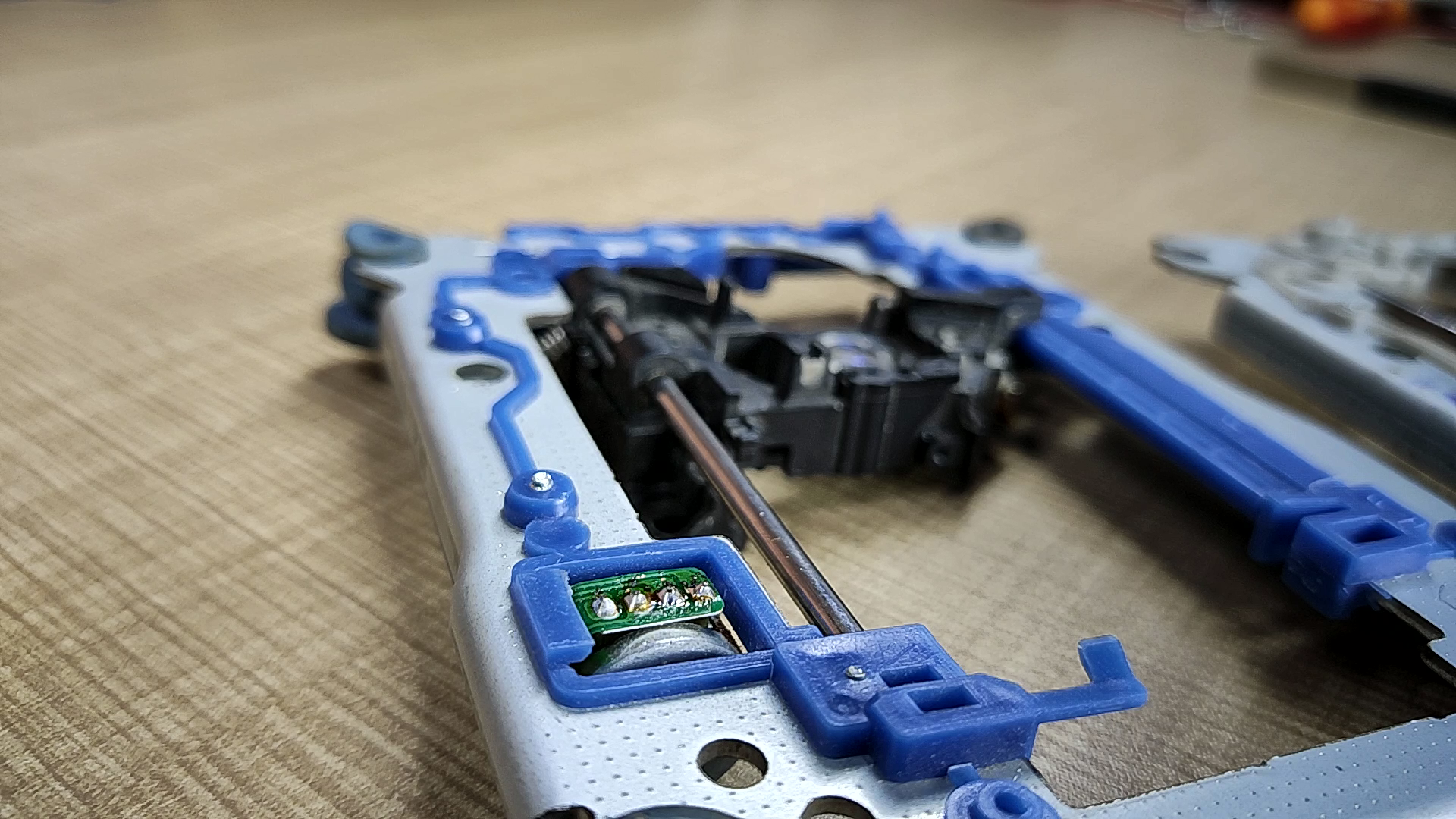
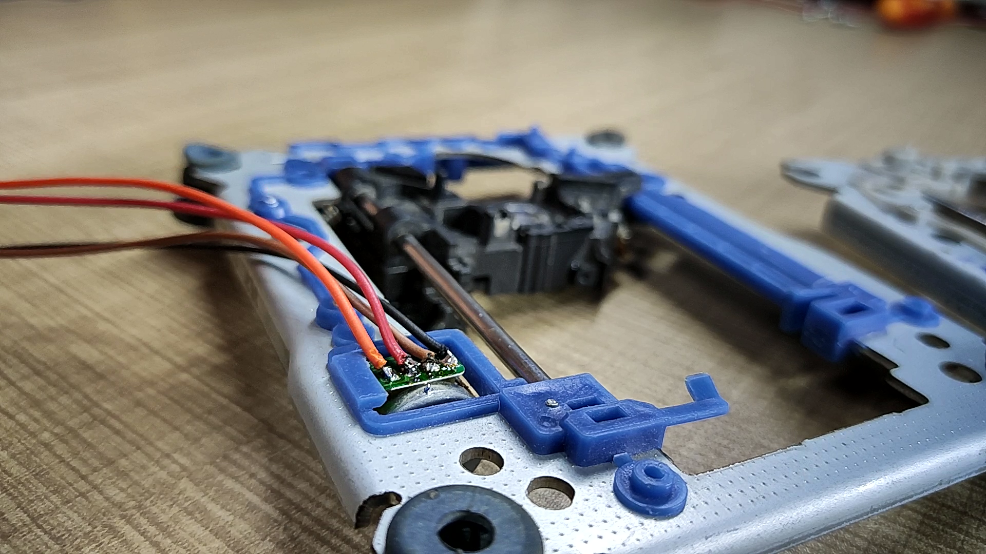
let's start.
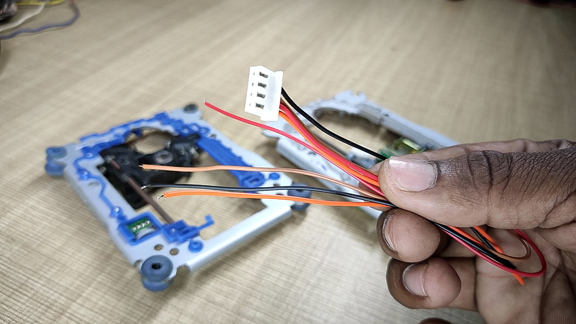
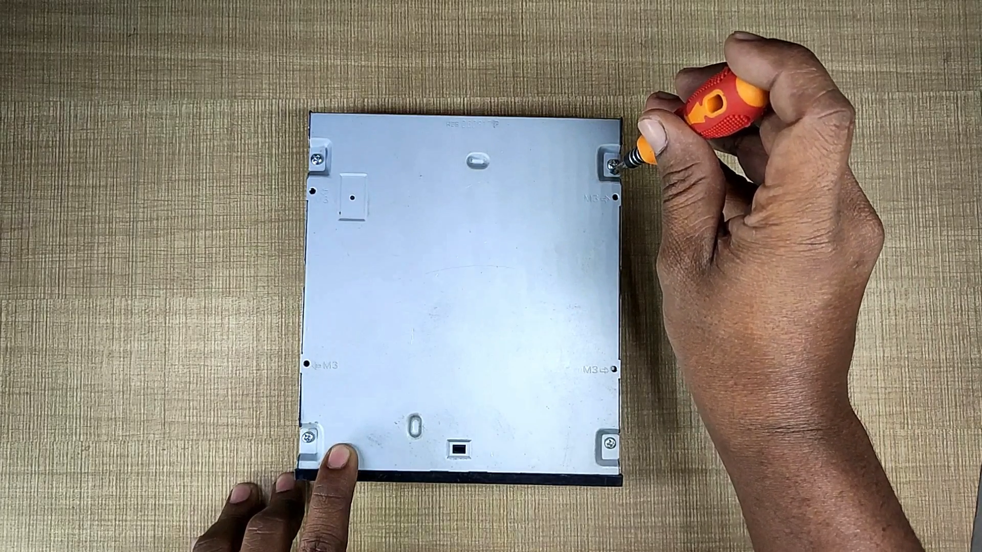
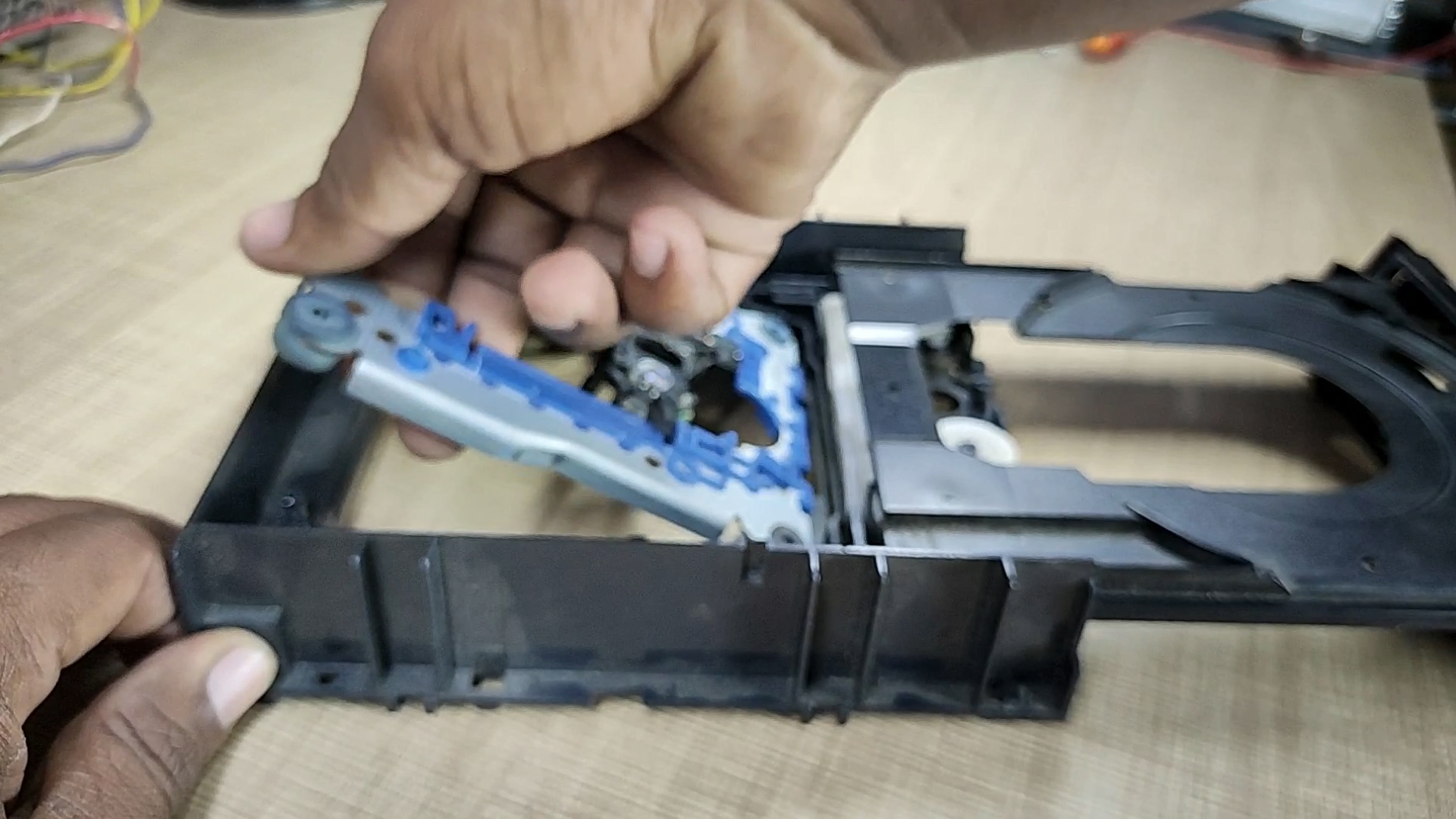
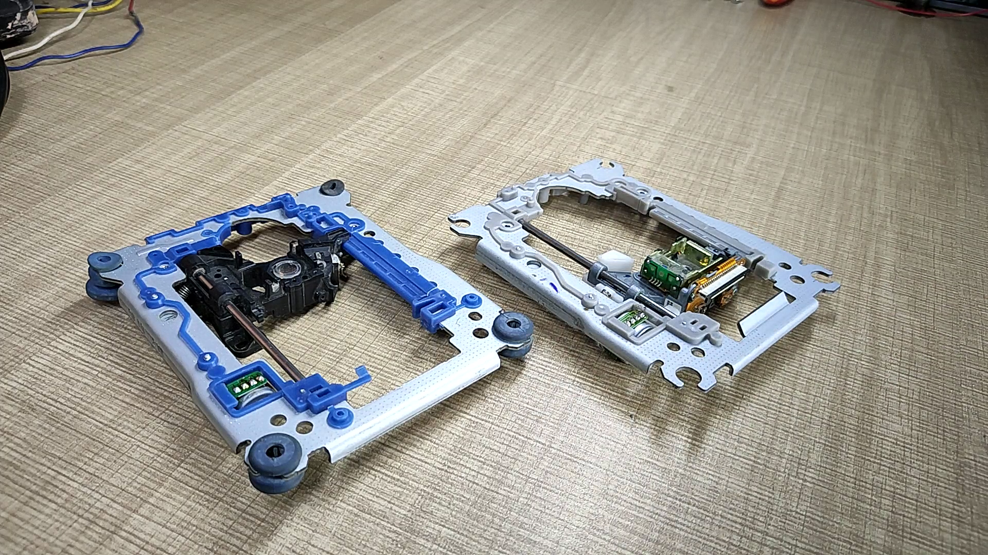
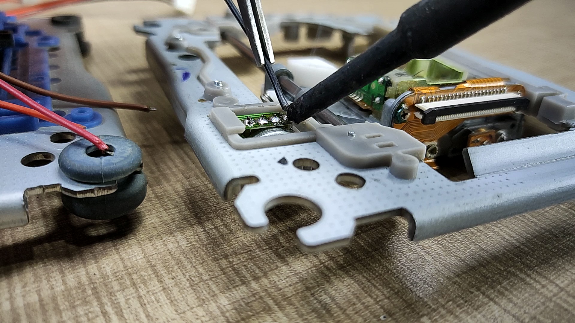
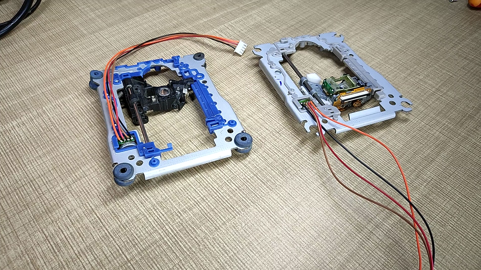
Open both DVD Writer and remove the lens driving assembly as shown in the pictures. this assembly has two motors one is bipolar stepper motor to drive read/write head and another is a BLDC motor to spin the Disk. remove the disk driving motor since we don't need this motor. we are going to play with the stepper motor in this project. solder wires to the 4 points of the stepper motor. solder wires to both motors.
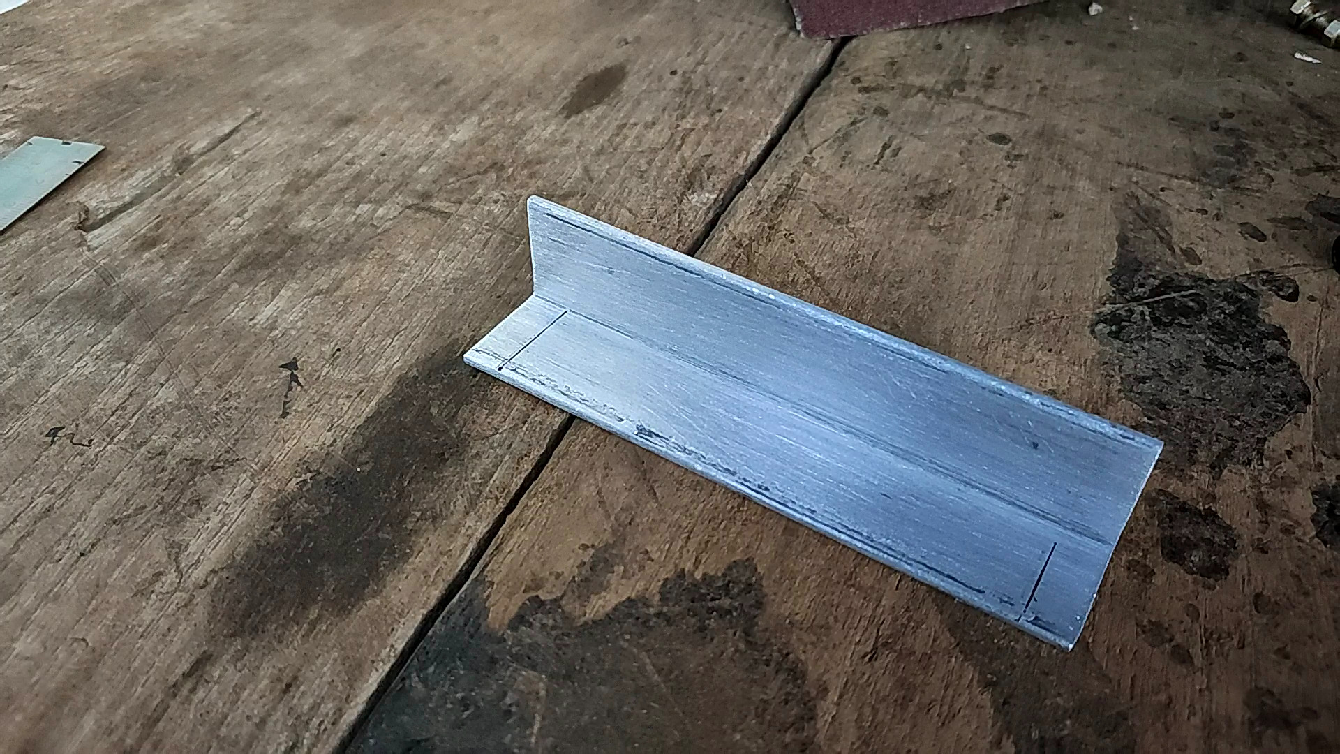
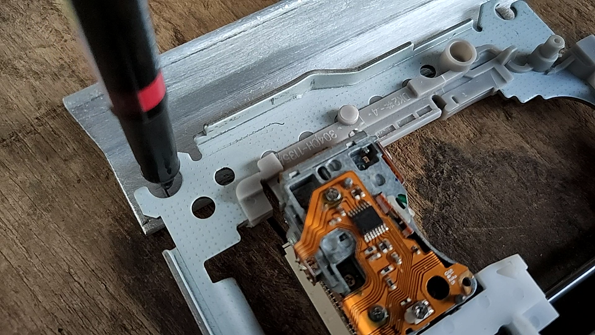
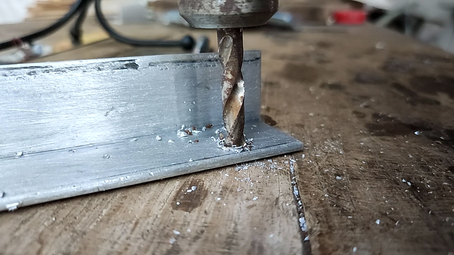
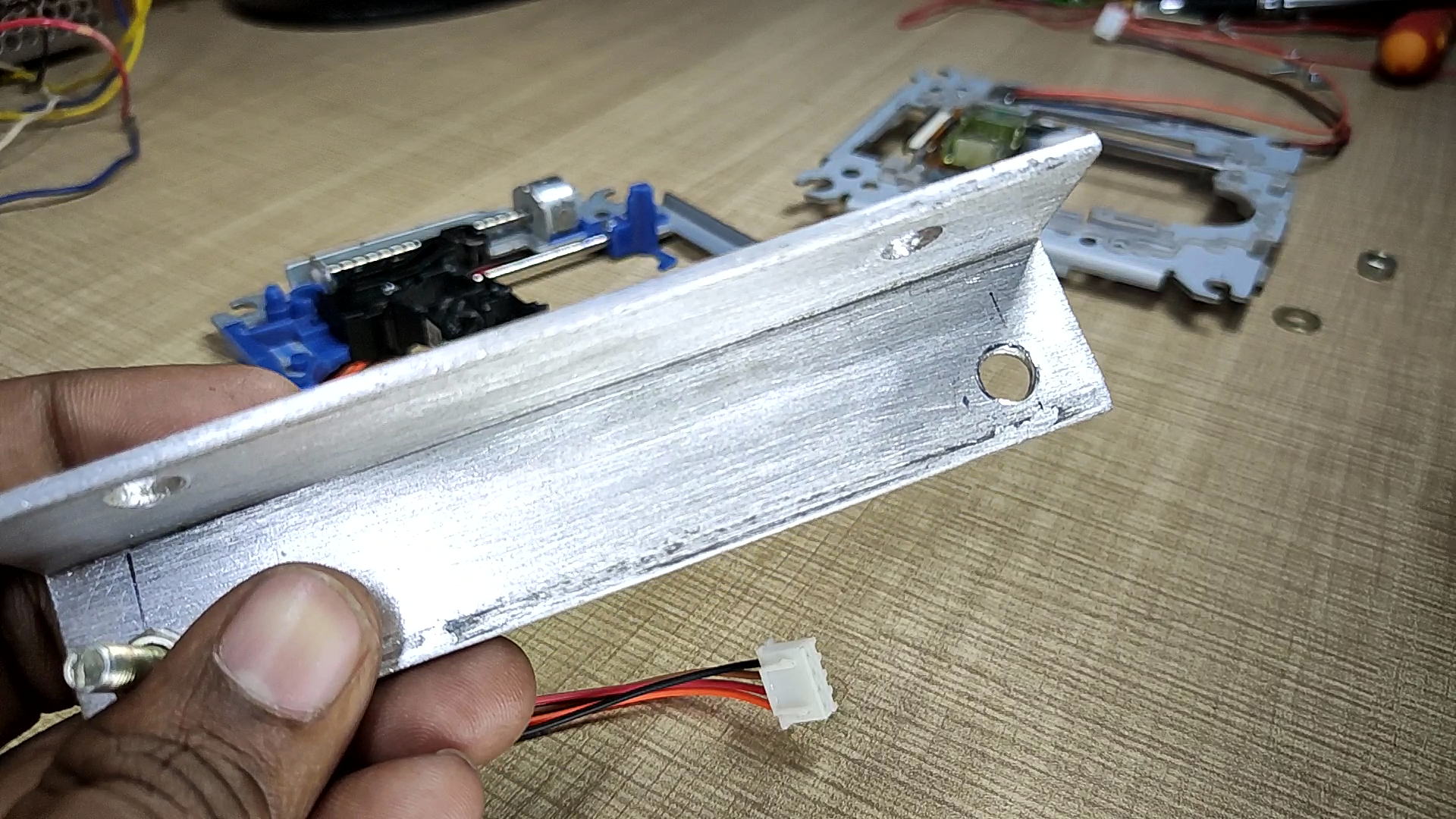
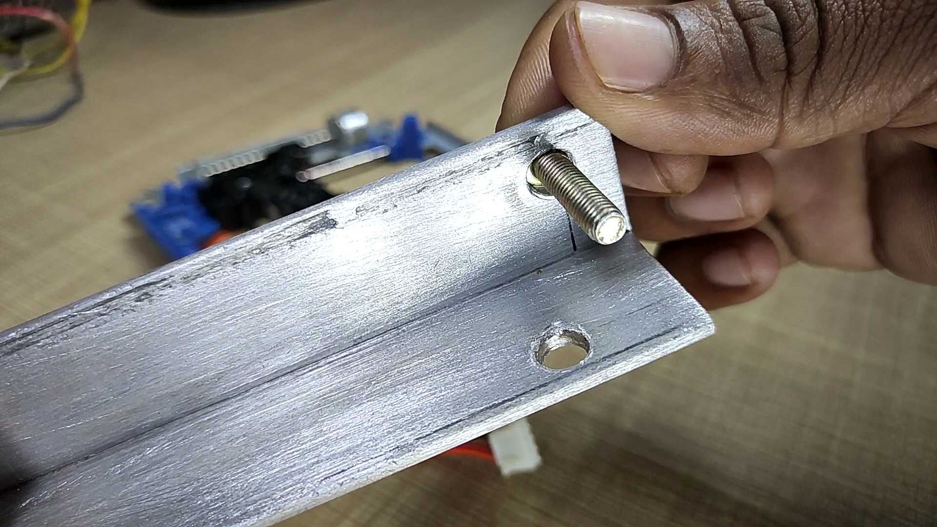
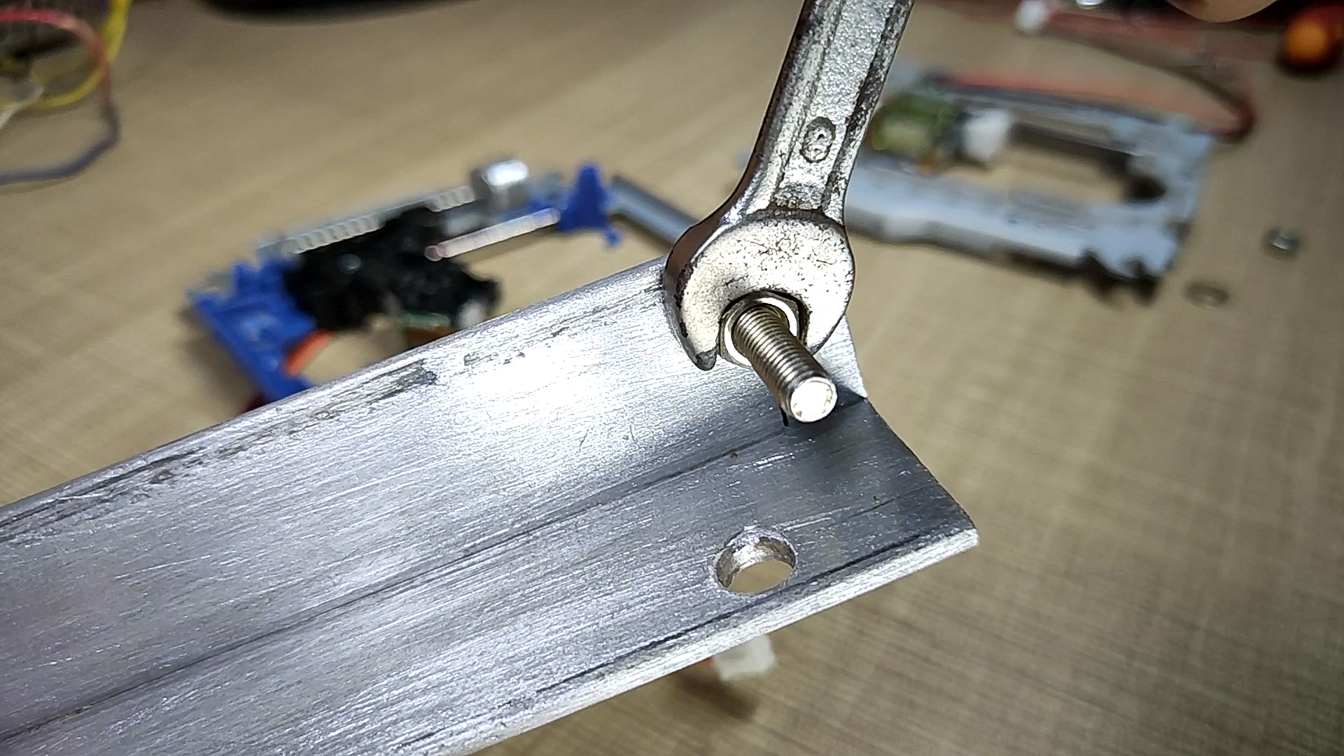
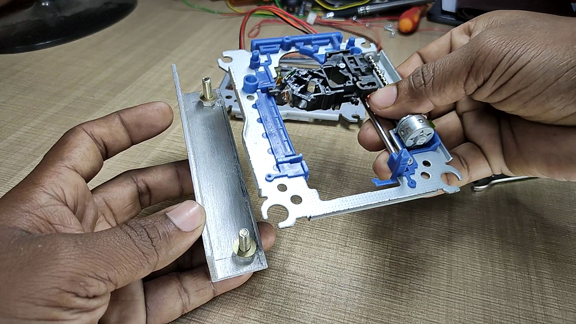
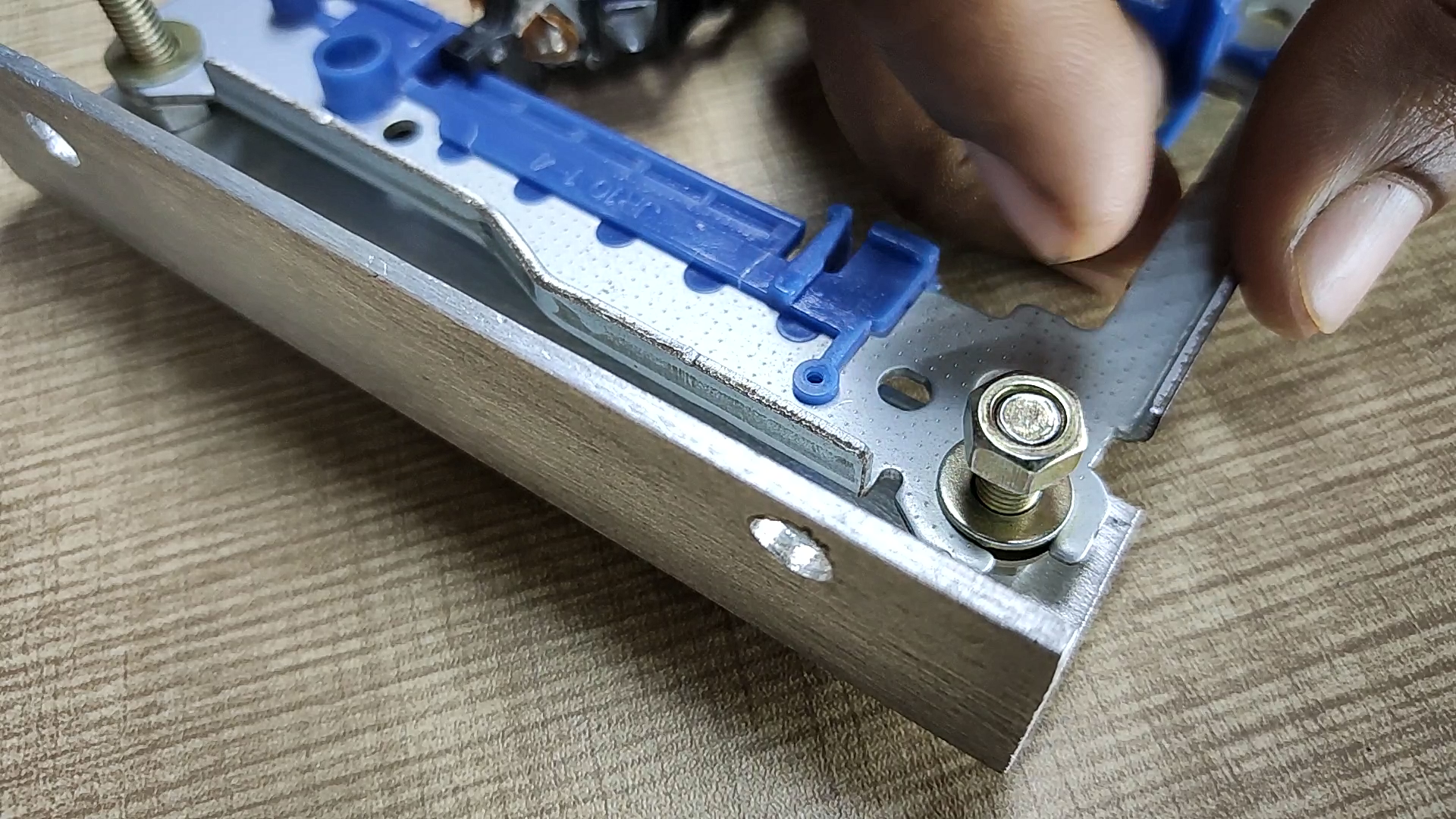
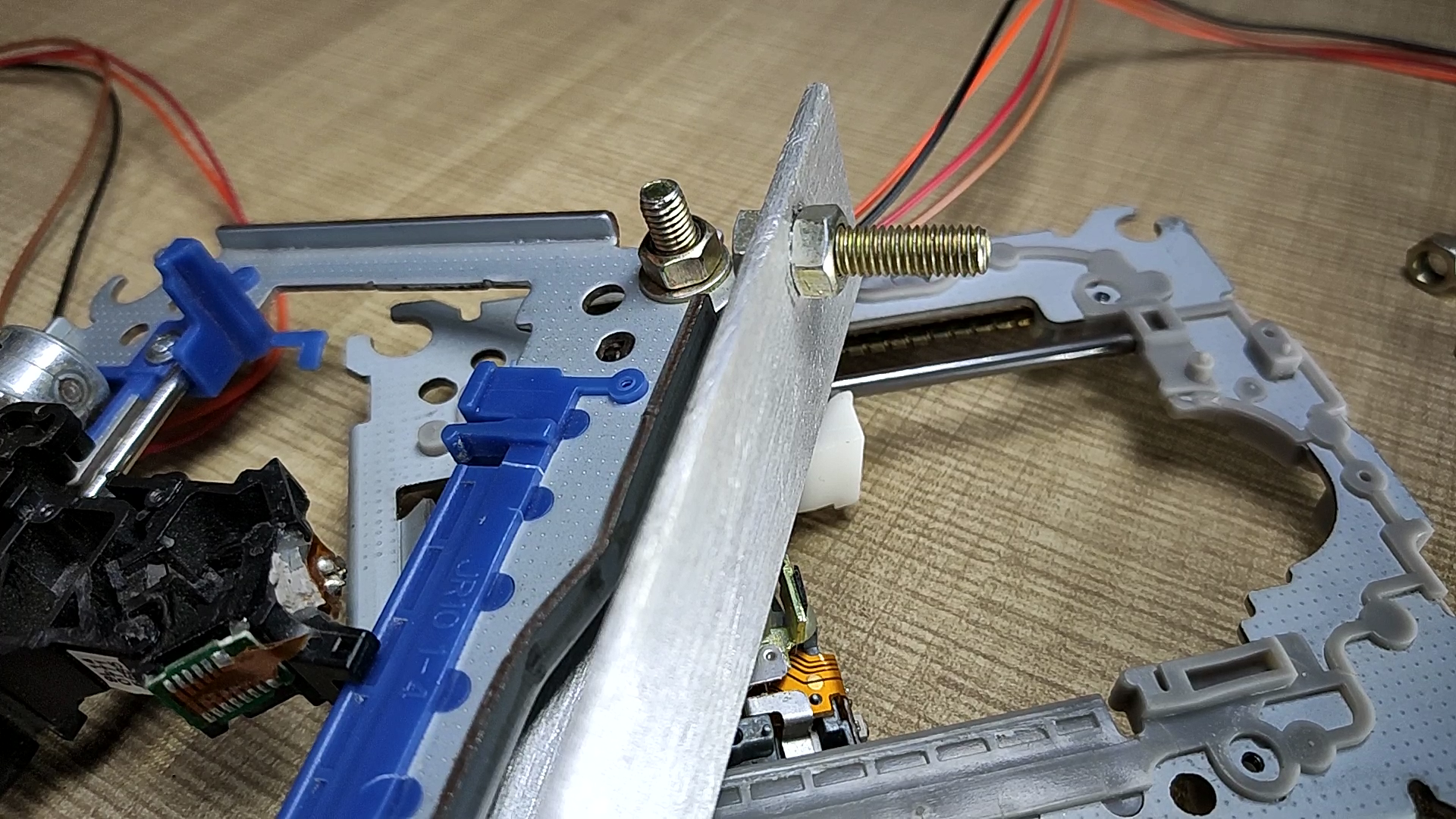
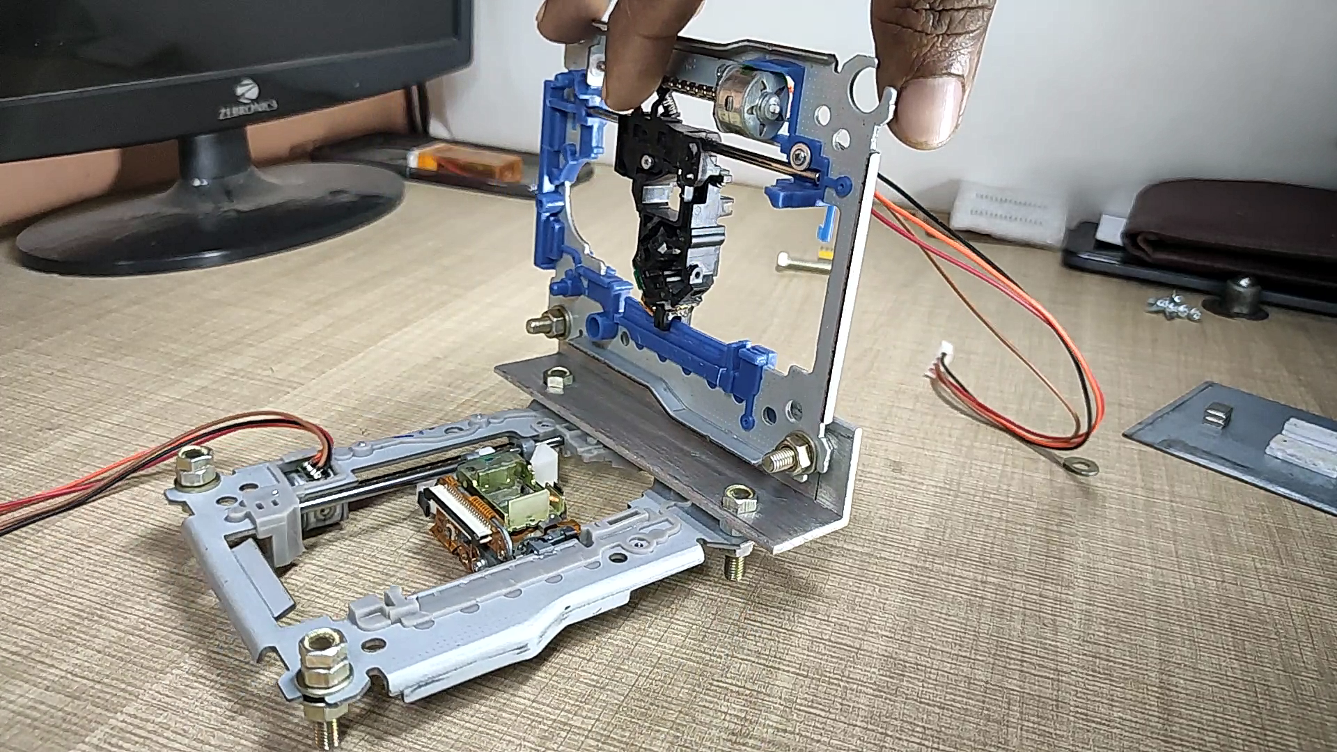
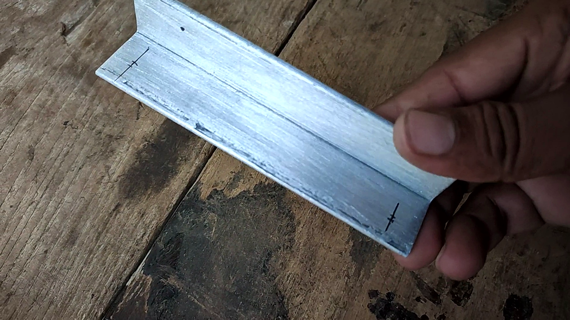
Now take a 120mm long piece of L shape aluminum, mark on it for drilling holes as shown in pictures. after drilling bolt both the lens assemblies with each other by using L shape aluminum. for reference see the pictures and assemble the body as shown. in this assembly, verticle fitted stepper motor will be Y-Axis and Horizontal stepper motor will be X-Axis
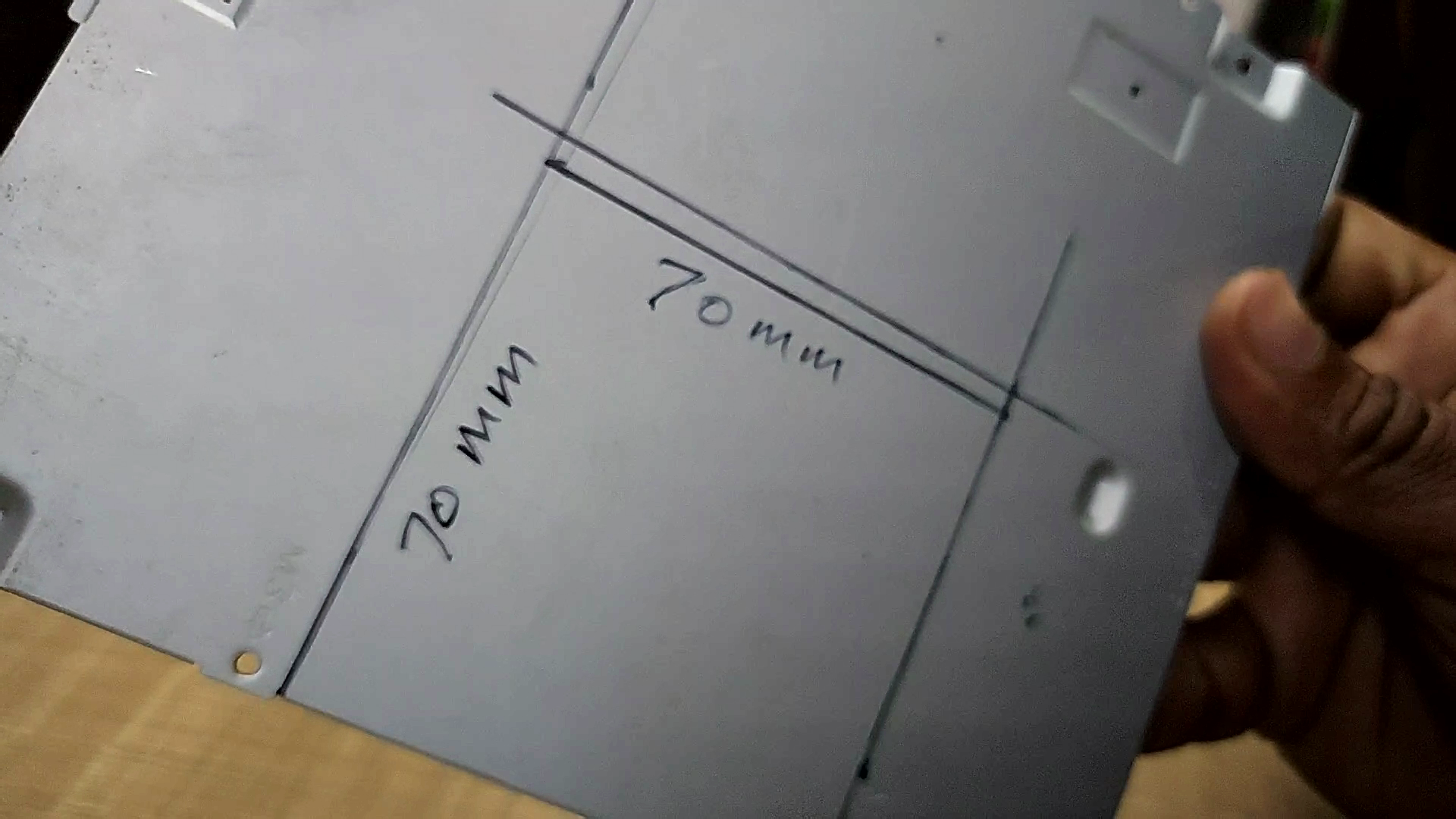
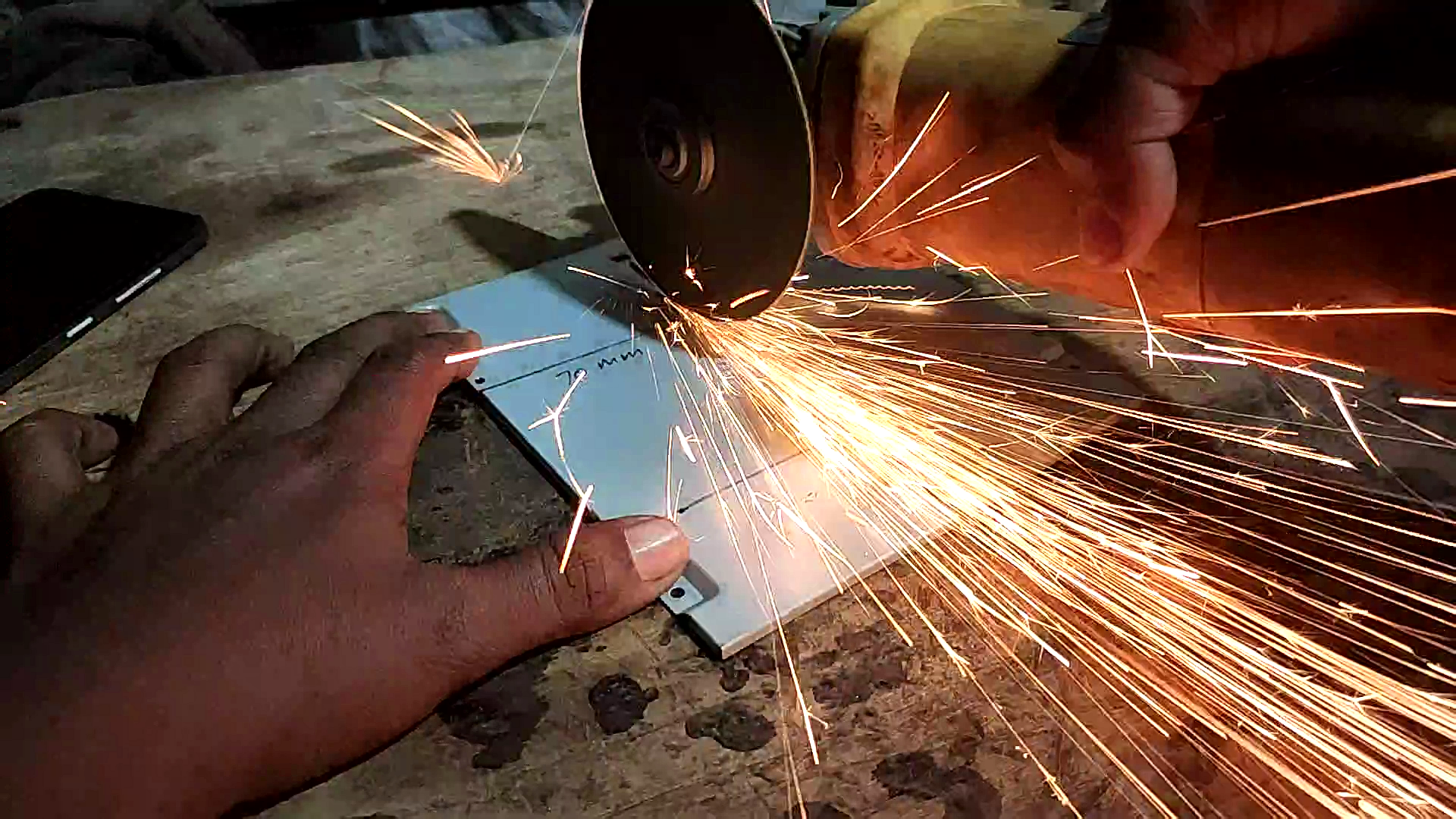
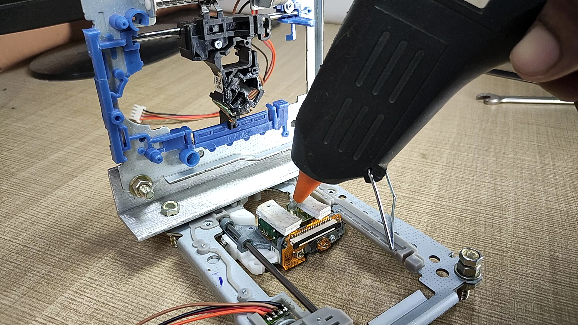
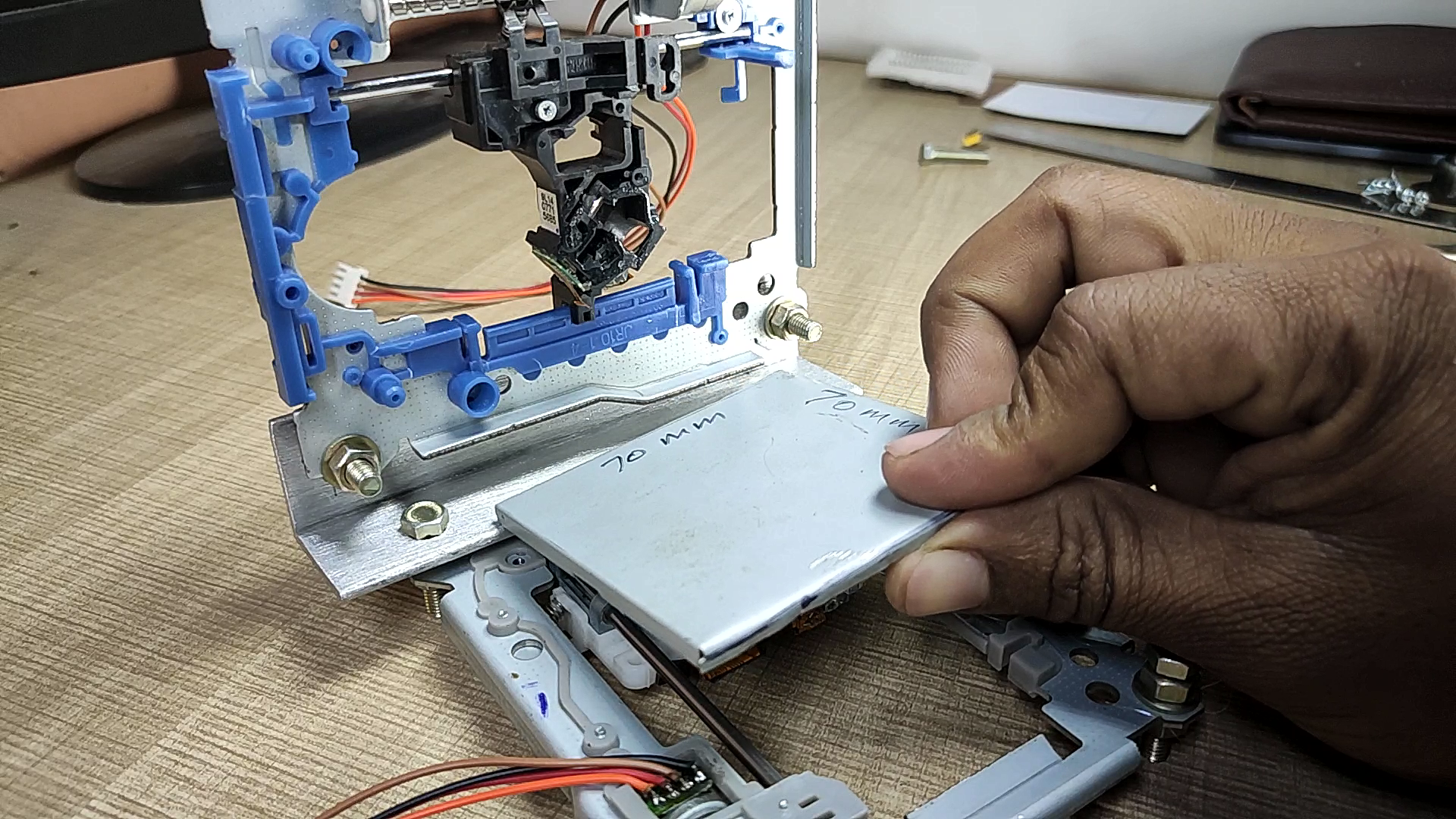
after making body it's time to make a bed (flat surface) for placing paper on the machine. to make it I using cover of DVD writer which is made up of about 0.6mm thick sheet metal. mark a square of 70 x70 mm on it. and cut it using Angle Grinder. now put some hot glue on center part (moving part) of lens and stick the cut piece of sheet metal on it in such a way so that it can move freely. see pictures.
Making a Pen Holder
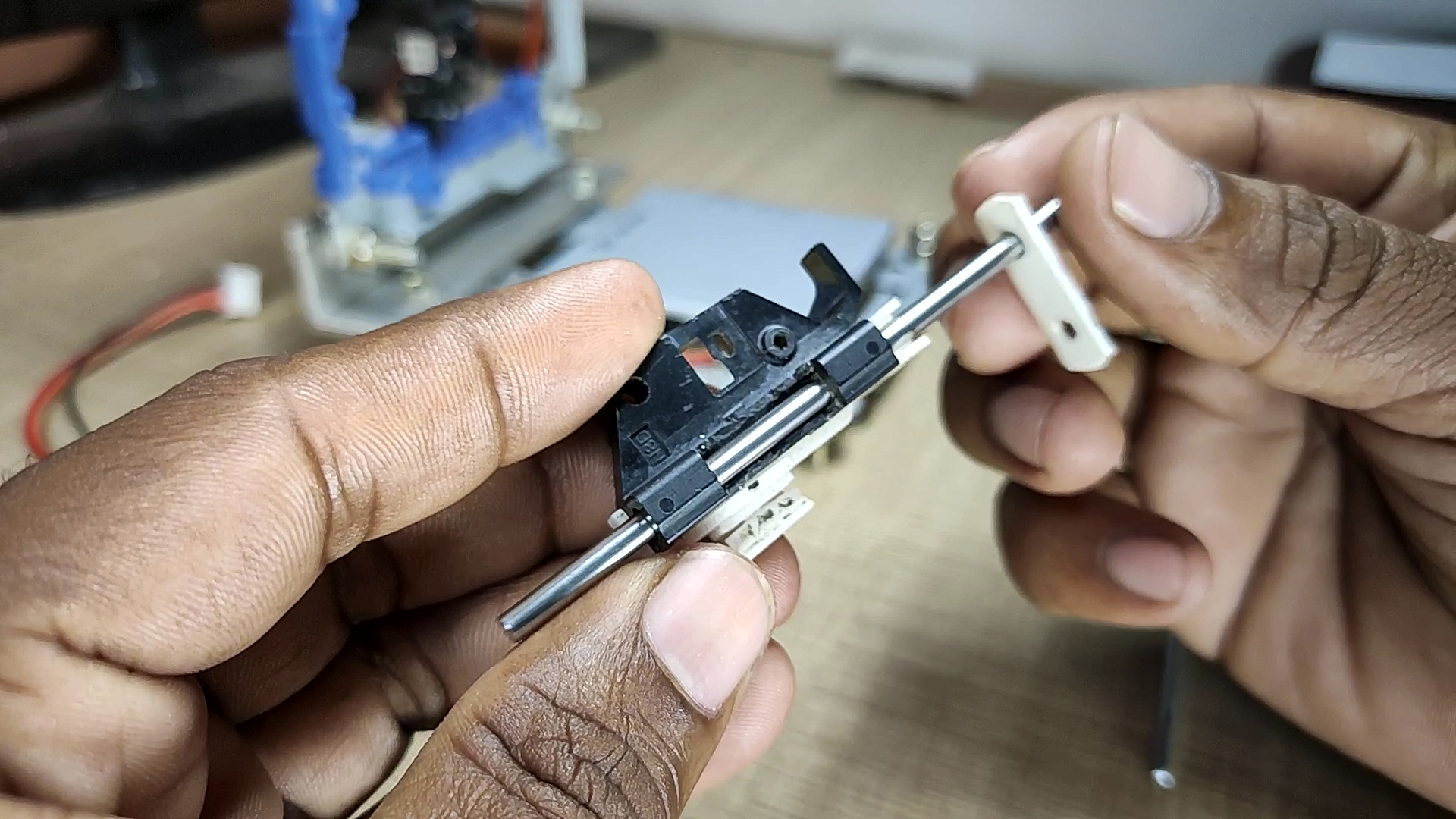
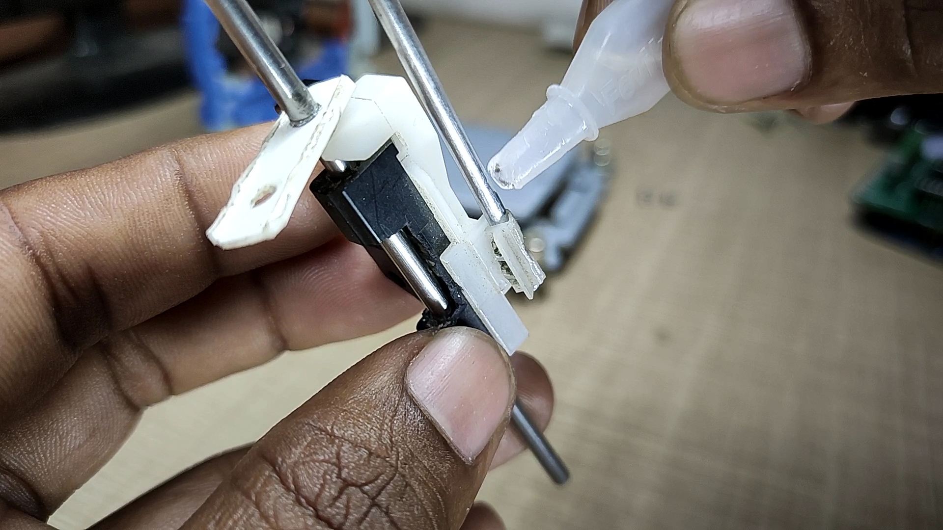
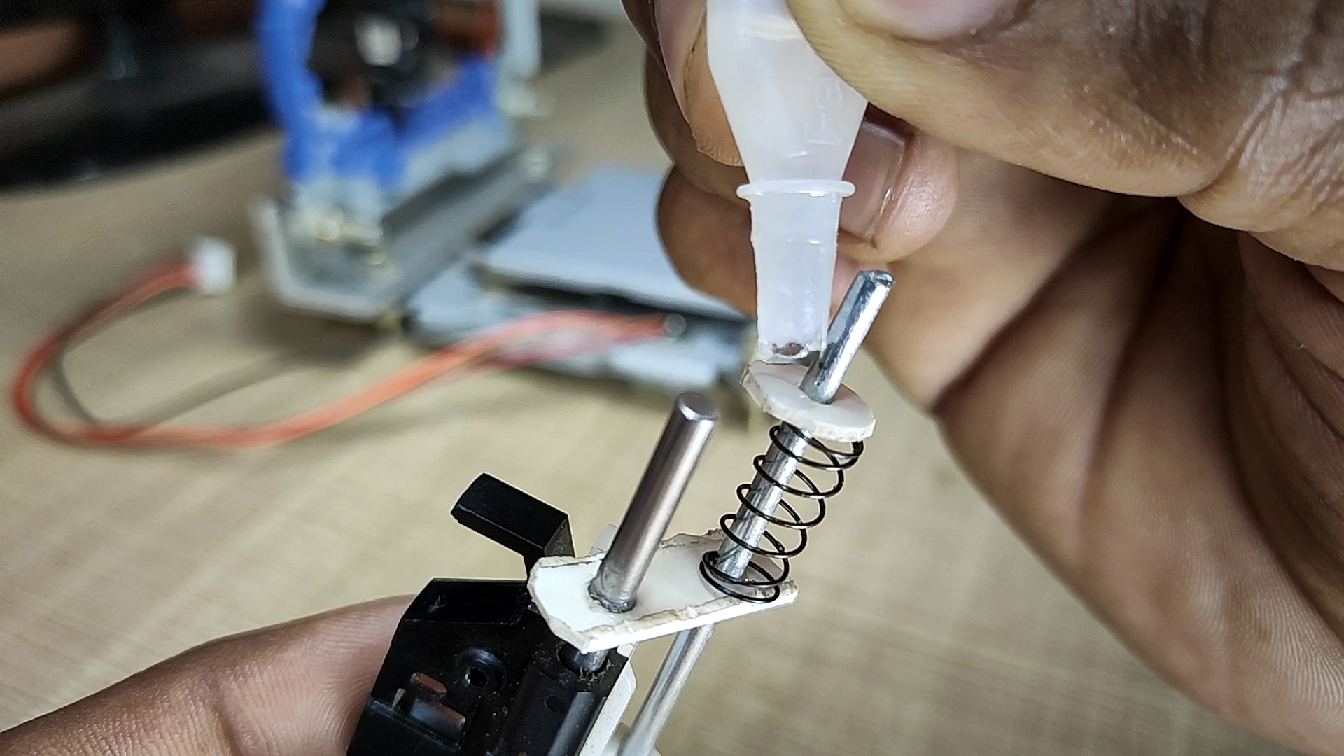
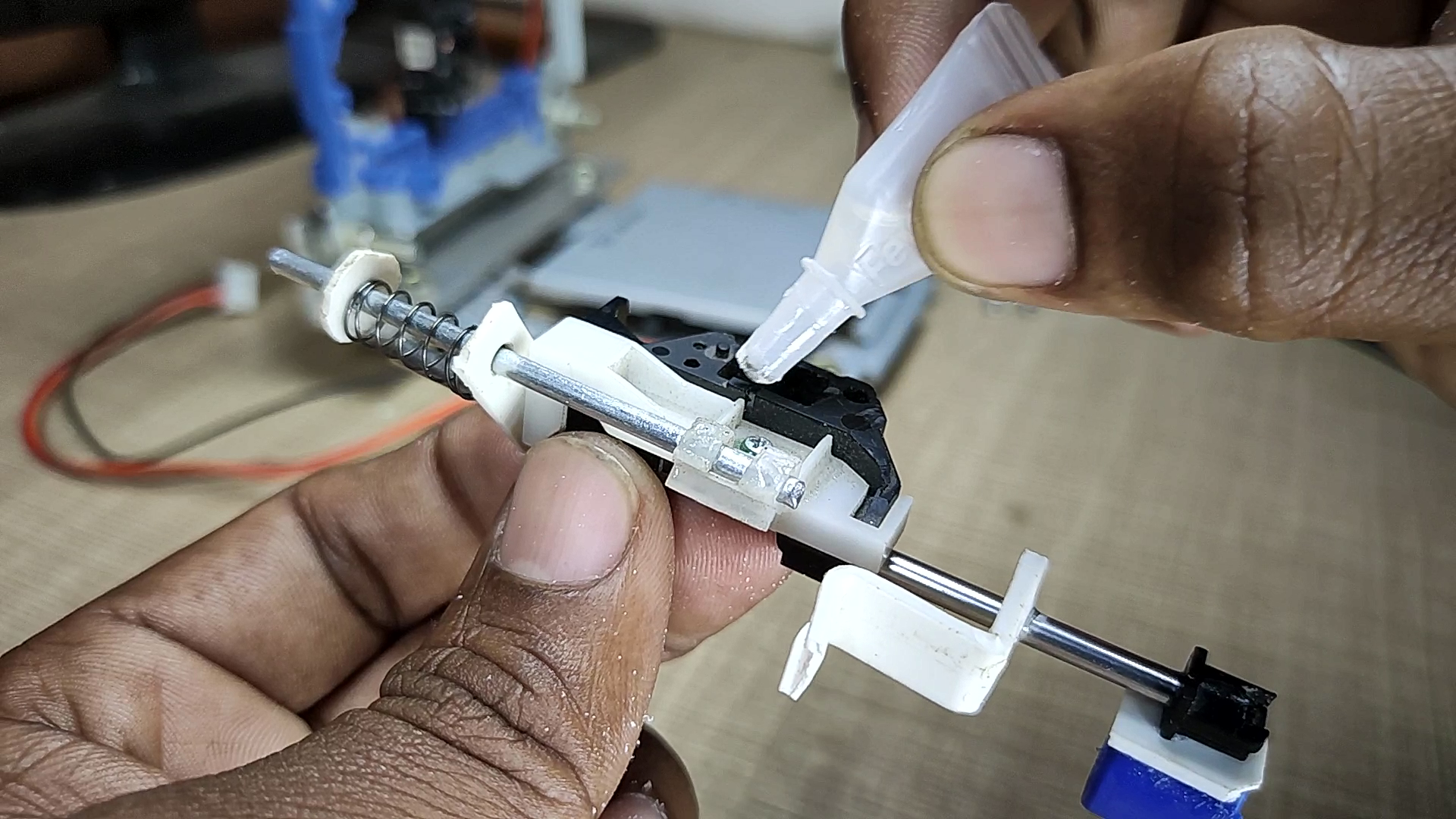
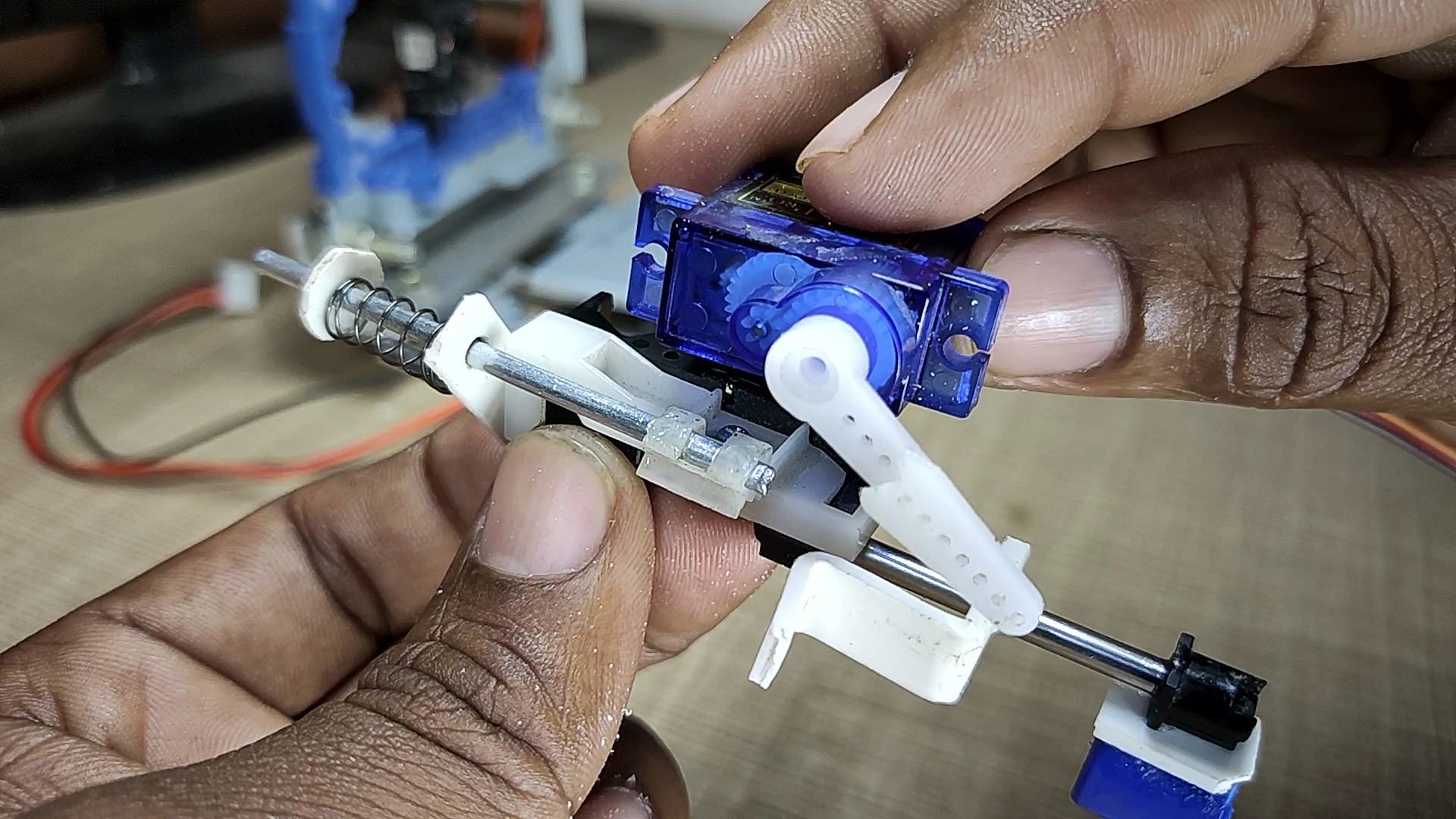
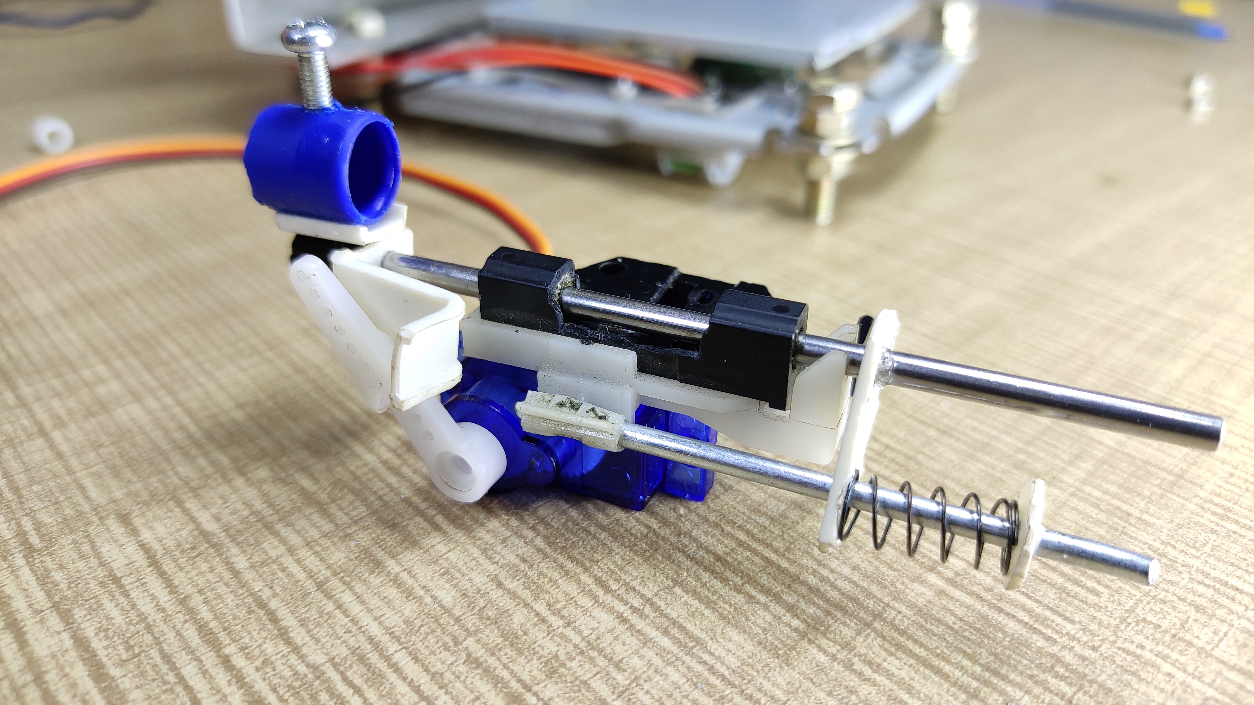
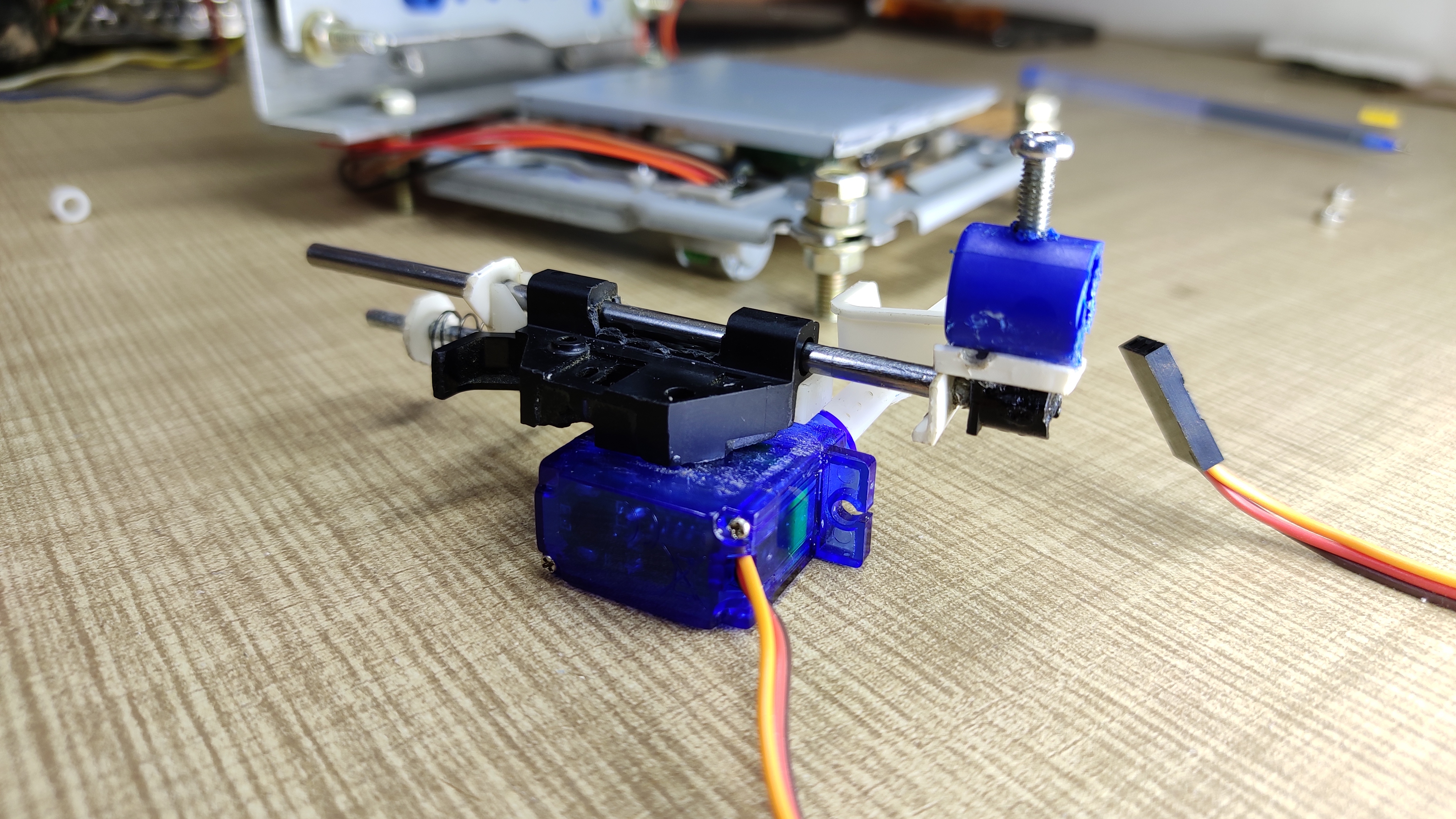
make the pen holder as shown in pictures. to make it I cut a sliding part from another old DVD writer same as used for making X & Y axis. there is nothing more to explain about the pen holder. it's basically a z-axis of our CNC. here we are using a servo motor for up and down the pen.
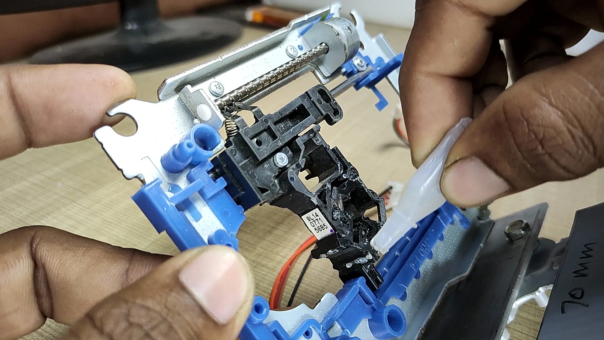
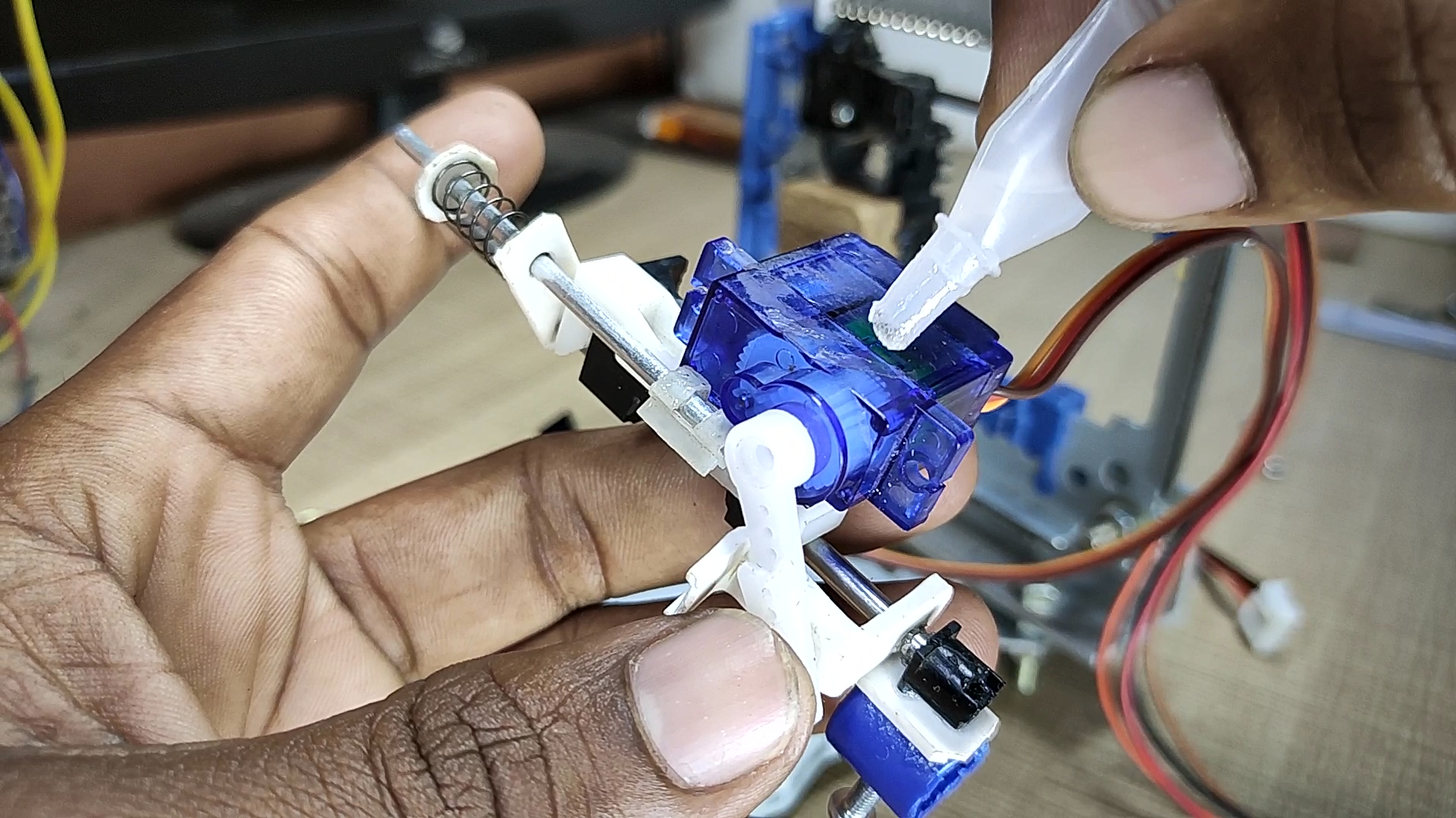
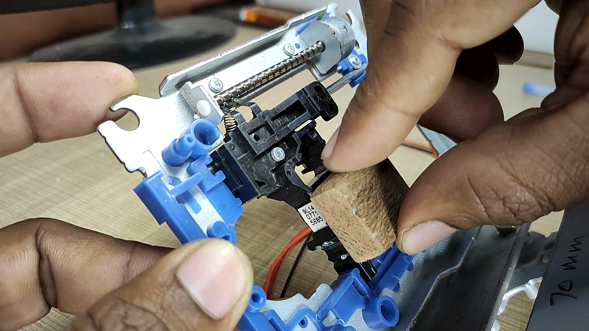
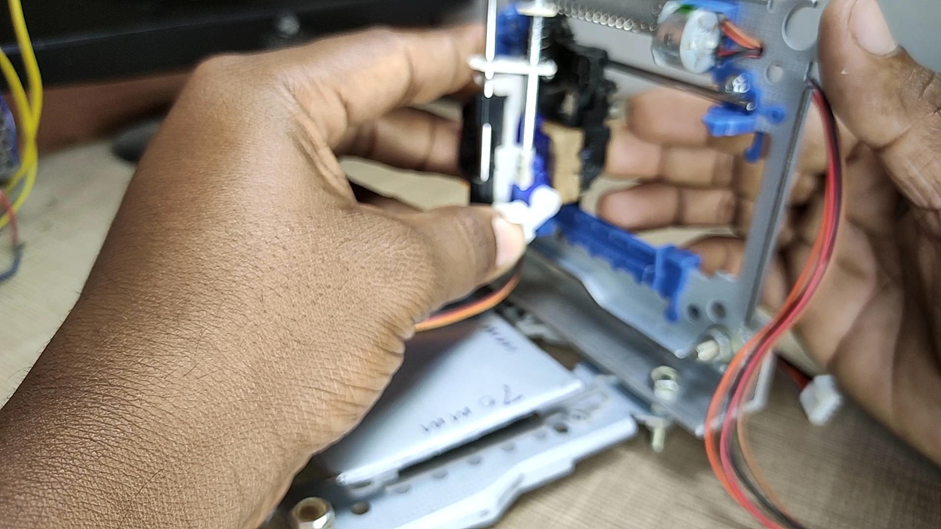
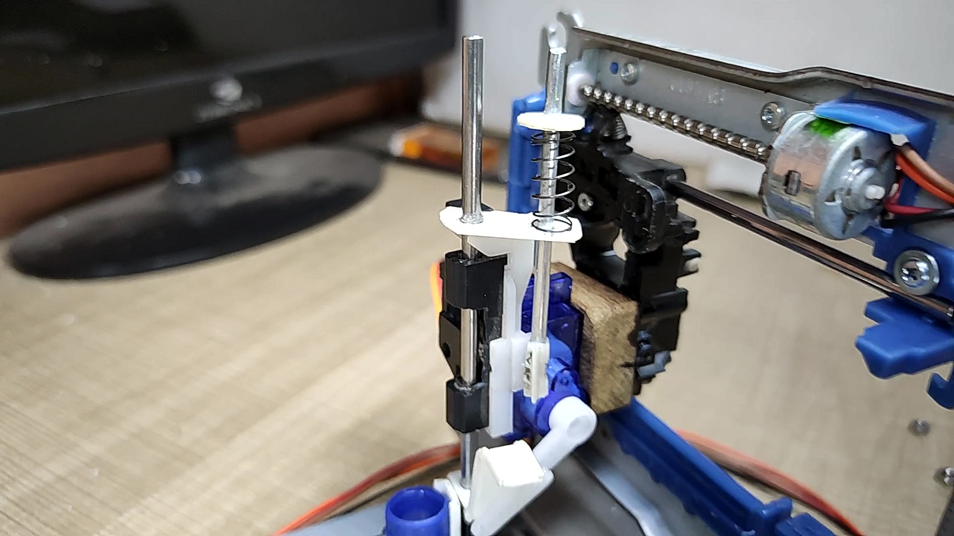
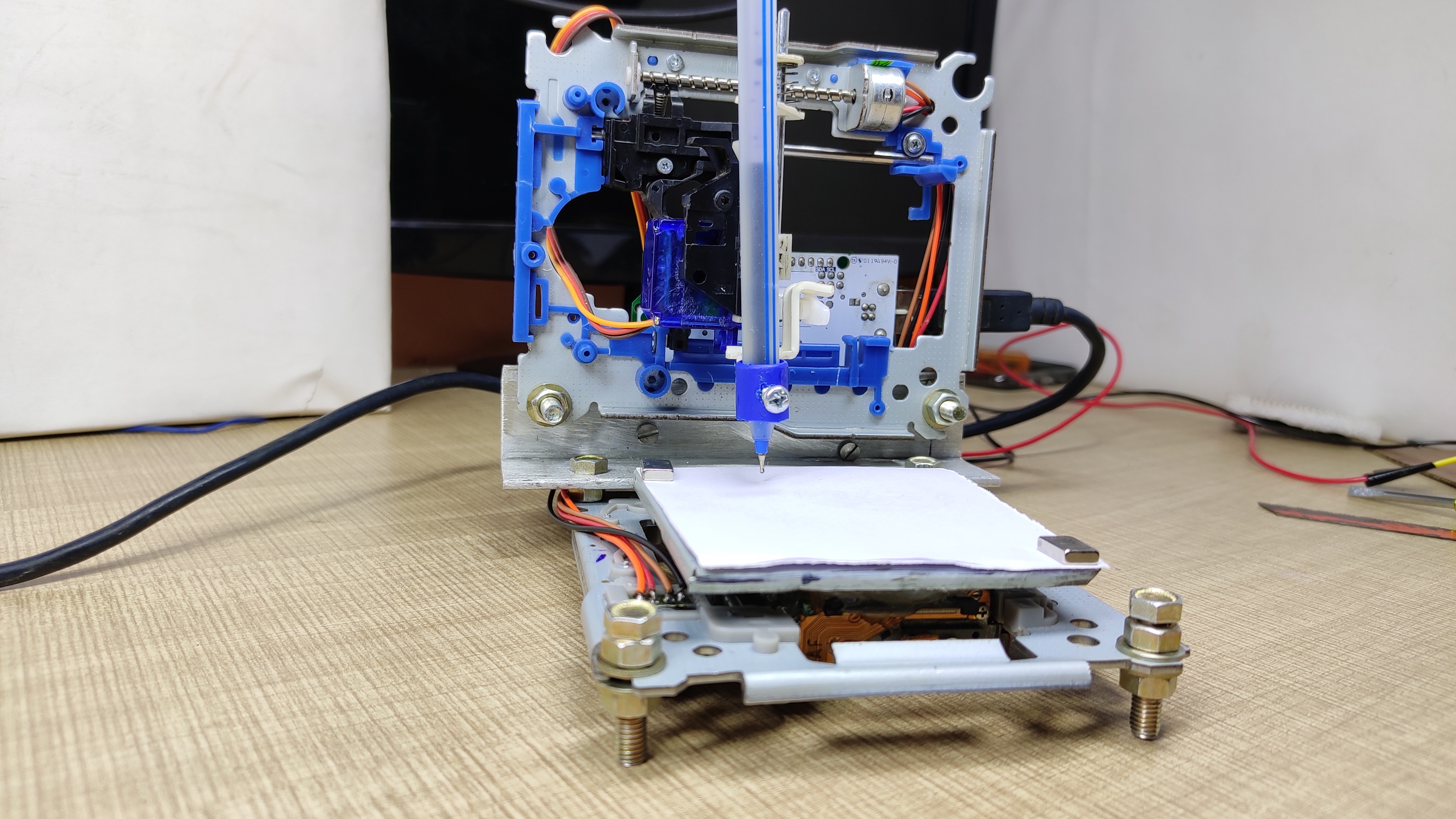
Fix this pen assembly on the vertical axis (y-axis) of the machine. I used a piece of wood to maintain a suitable space between the y-axis and the pen holder.
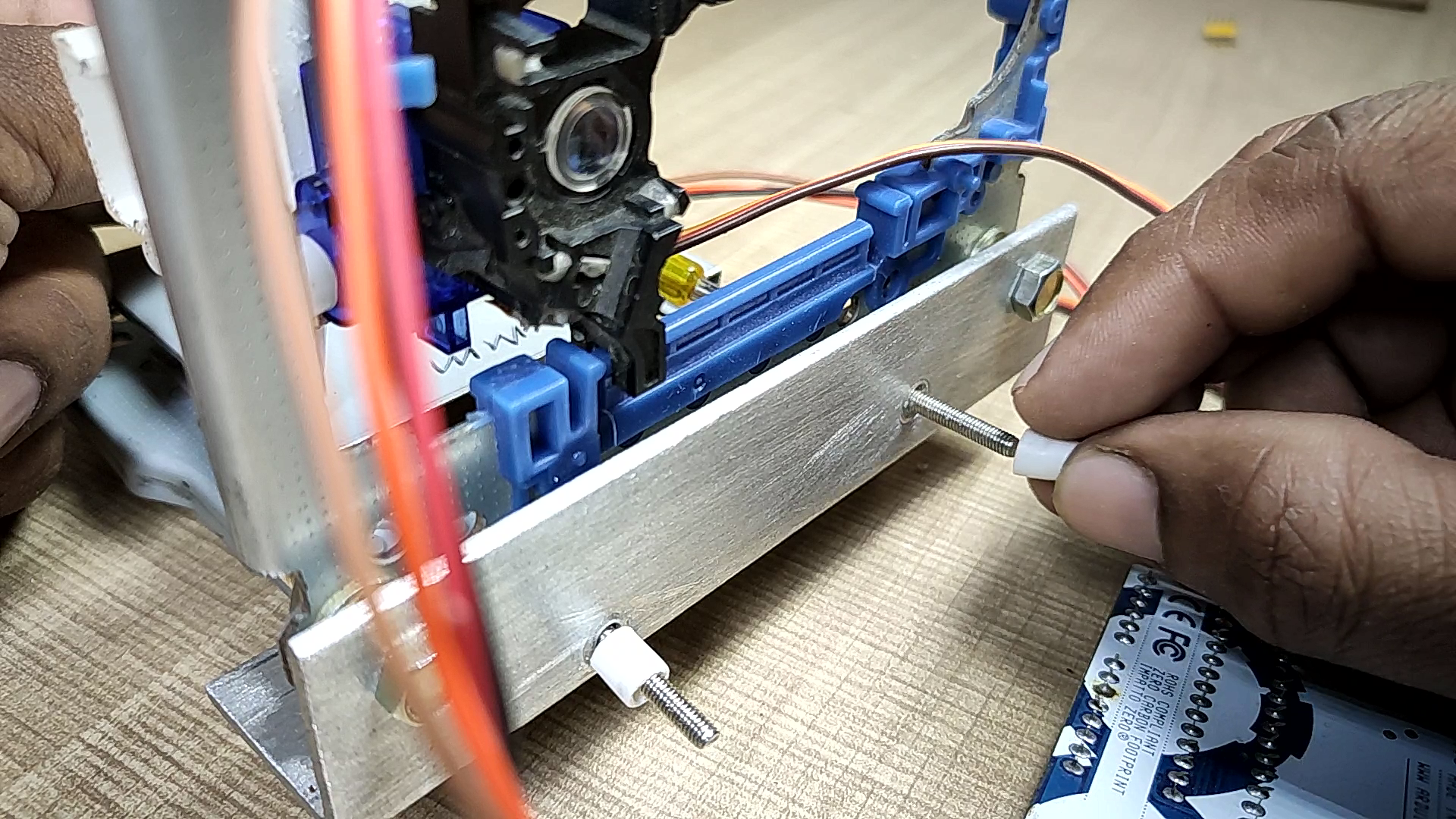
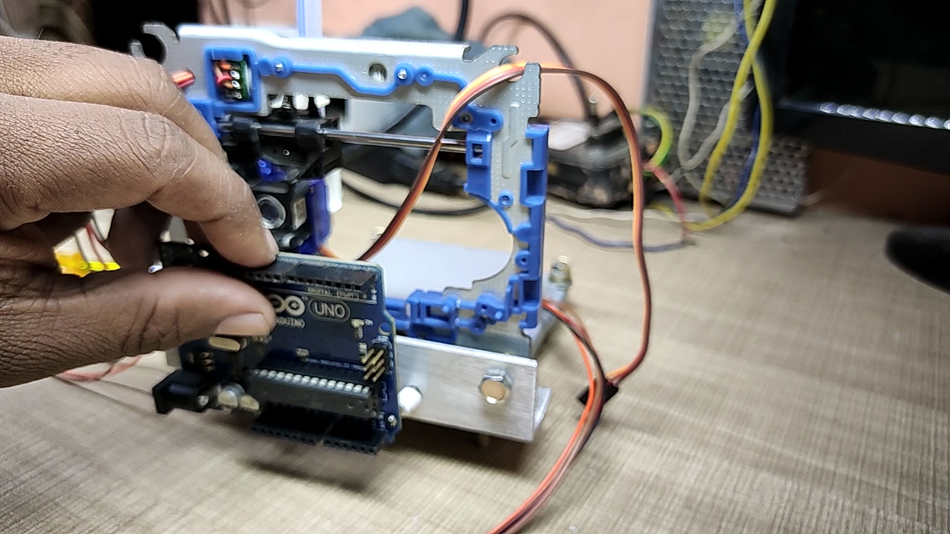
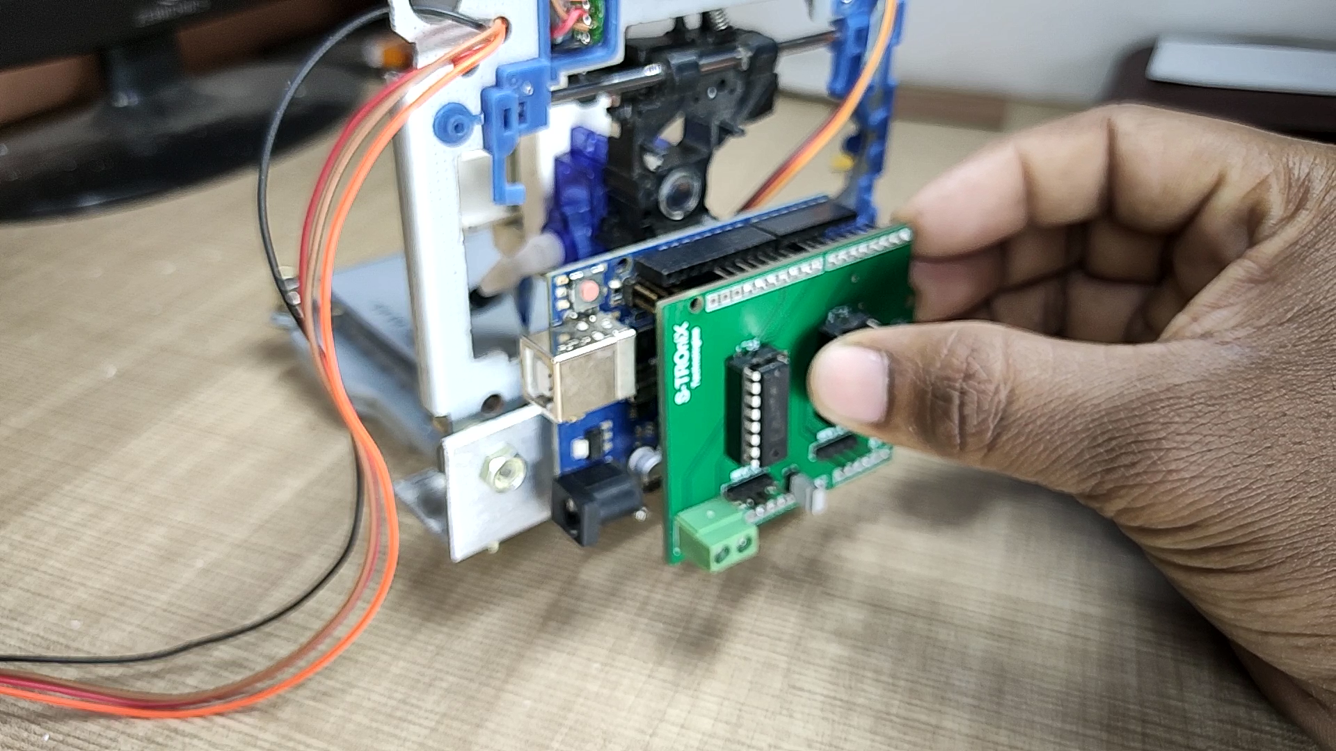
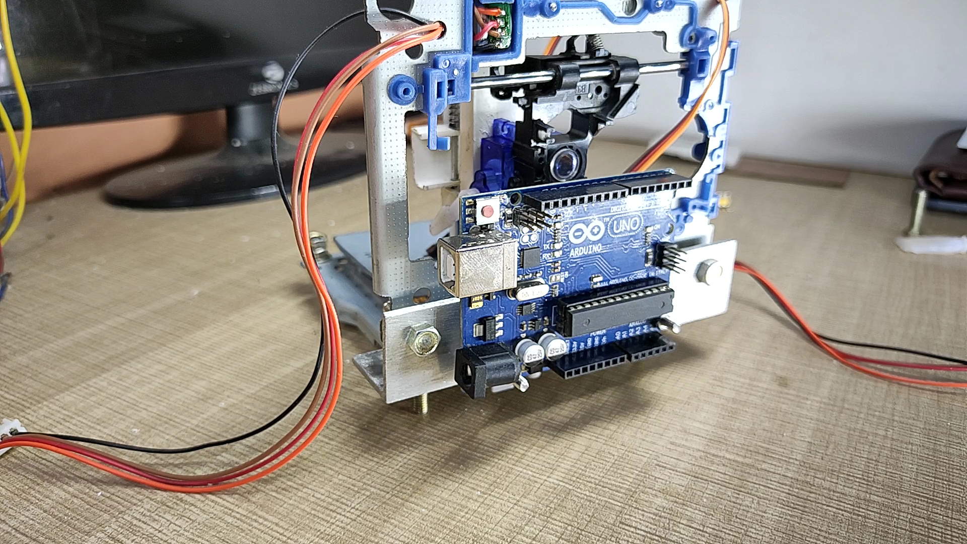
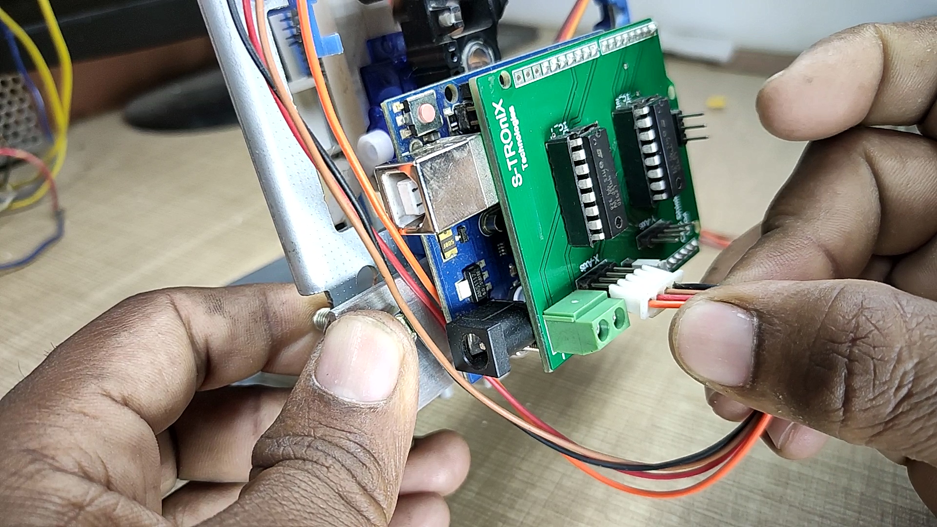
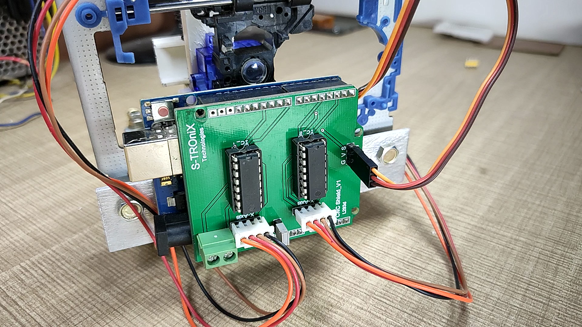
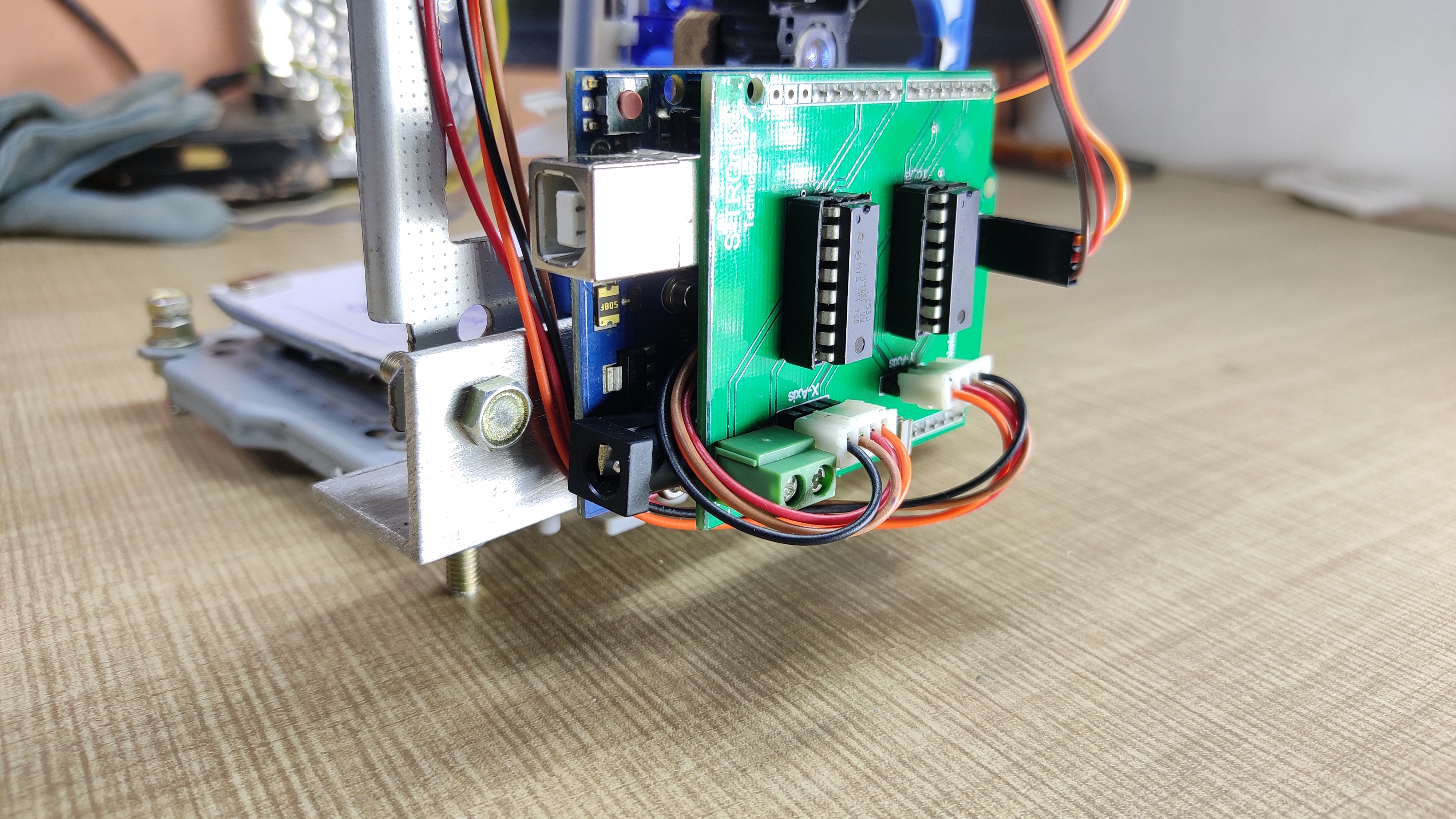
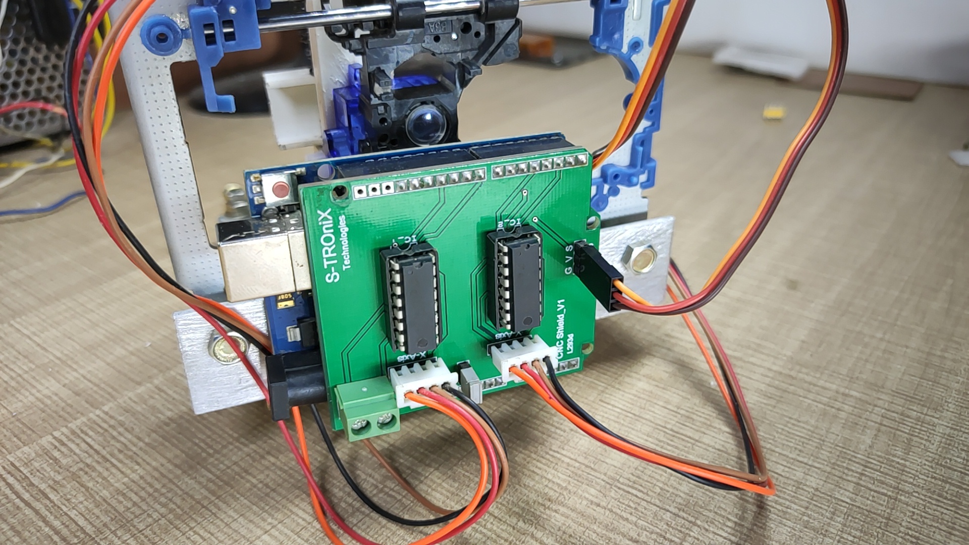
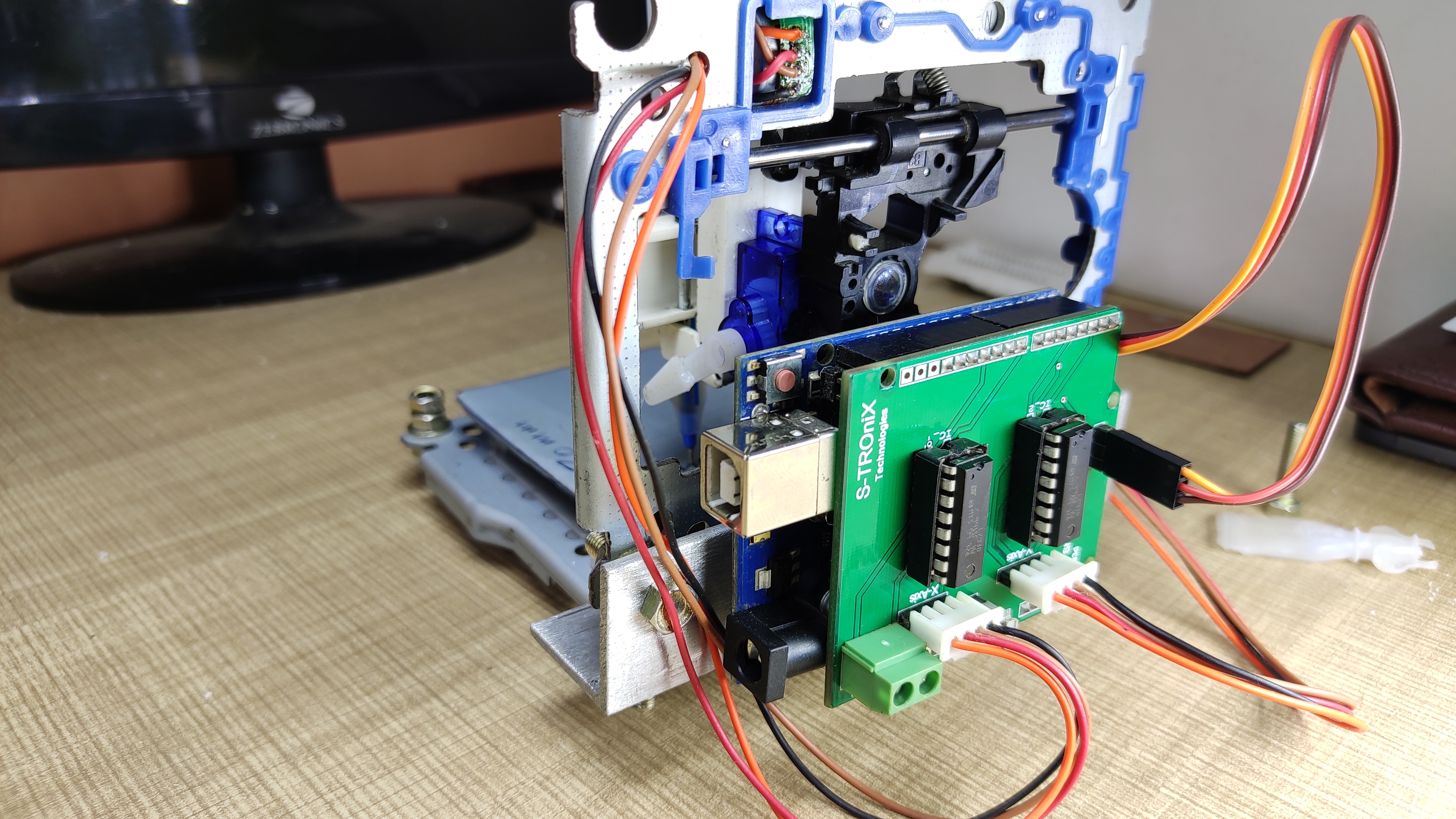
fit Arduino on the aluminum with the help of nuts & bolts as shown in pictures. and insert CNC shield on the Arduino. the CNC shield used in this project is designed by me. you can buy PCB for this shield from PCBway.com . now connect x-axis stepper motor on the X-axis output of the shield and y-axis stepper motor on the Y-output of the shield. connect servo motor on the servo connector of the shield.
Programming and Operation
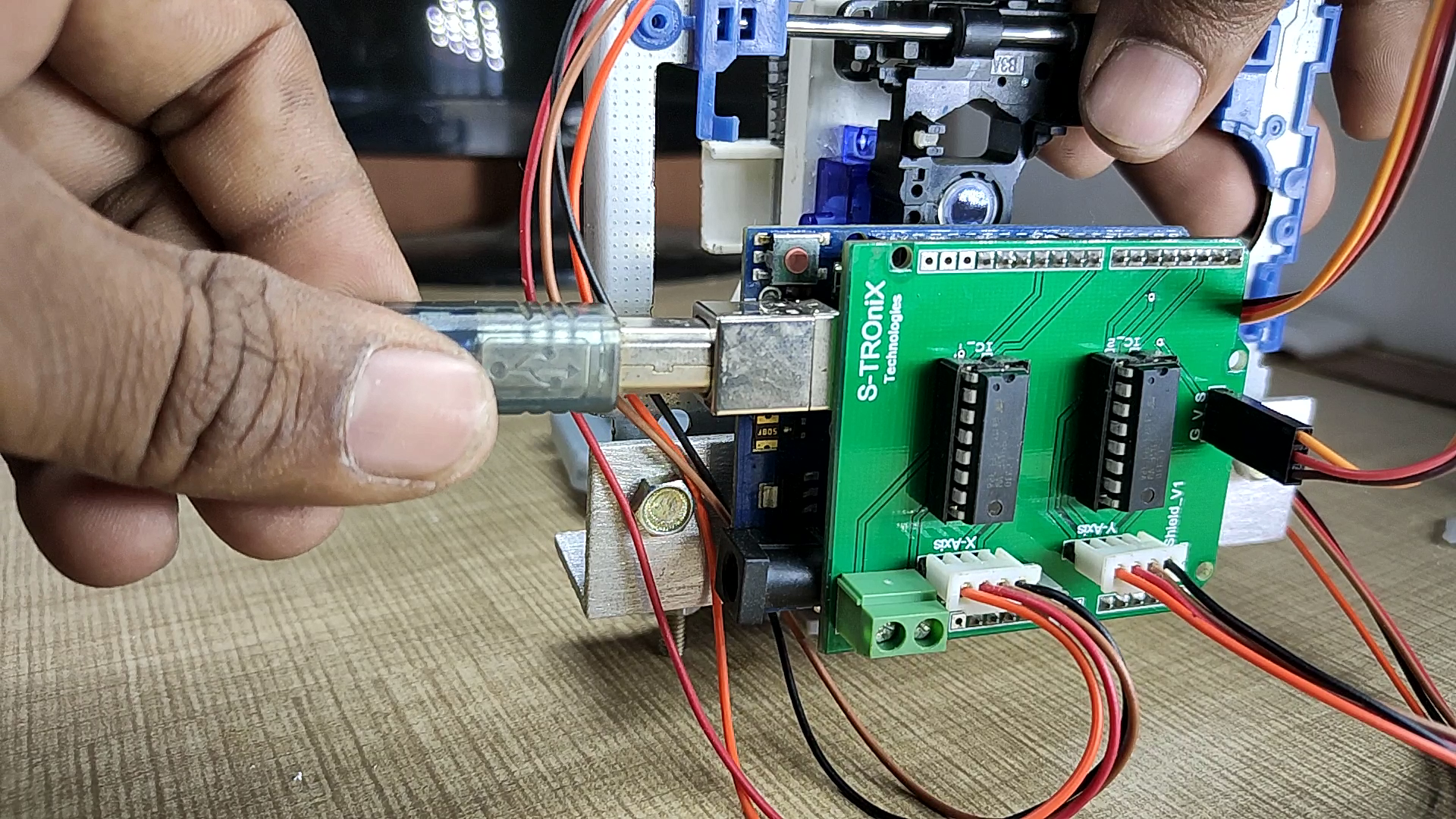
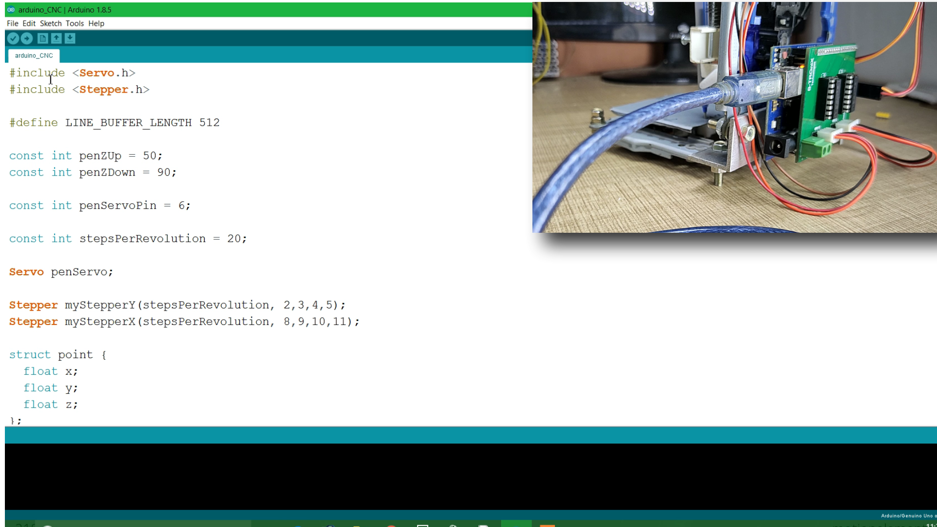
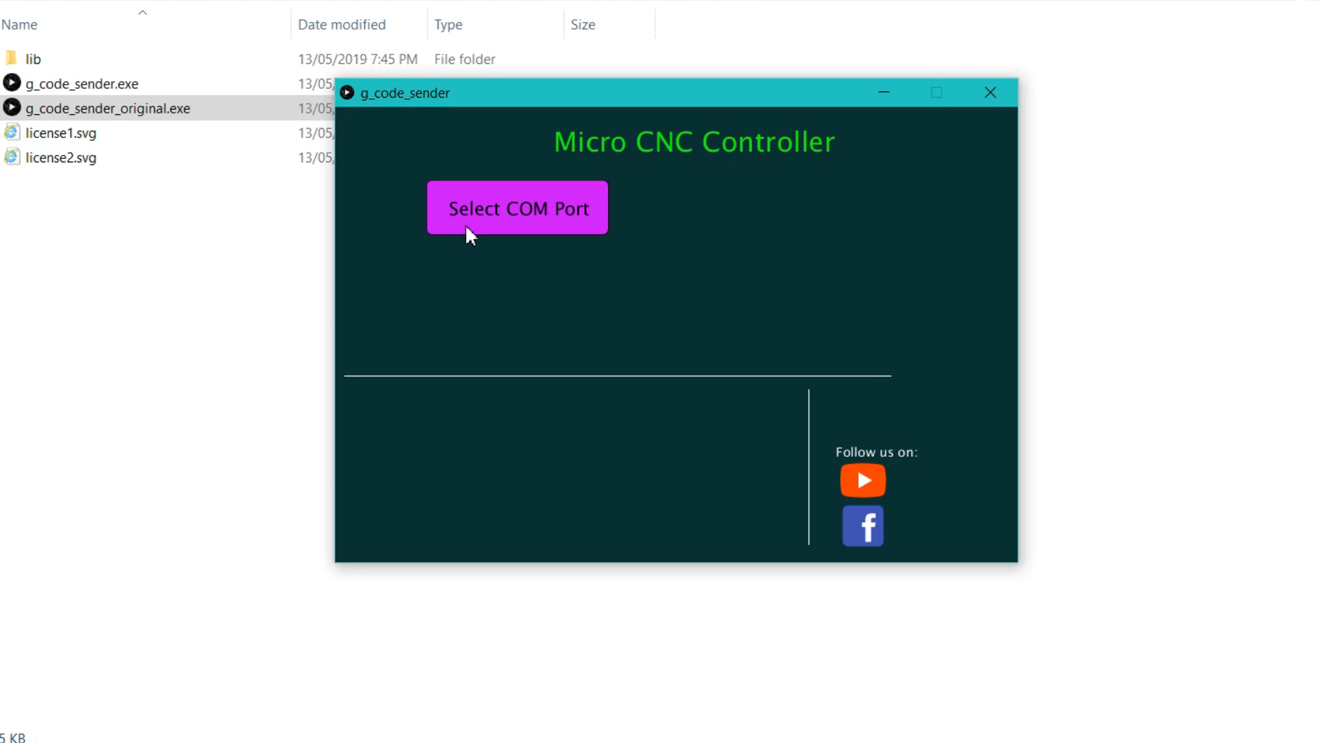
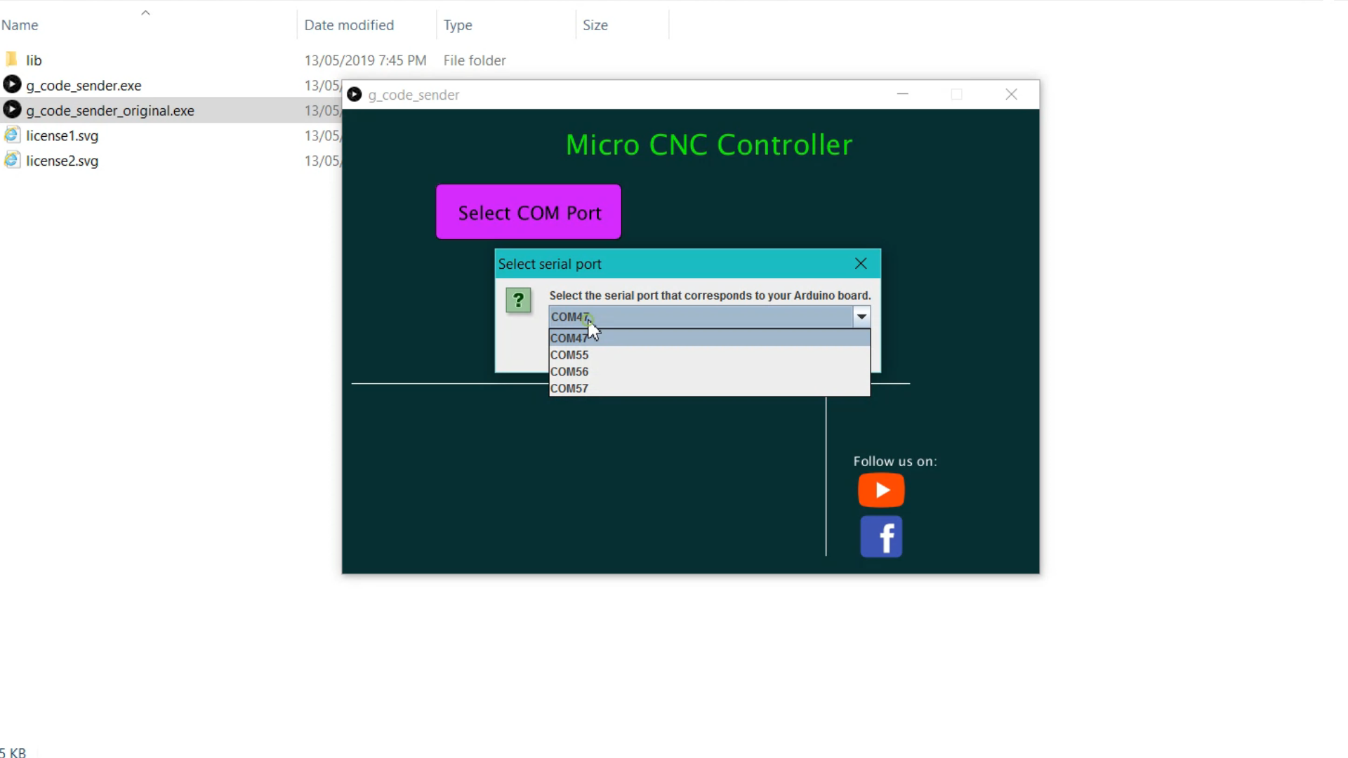
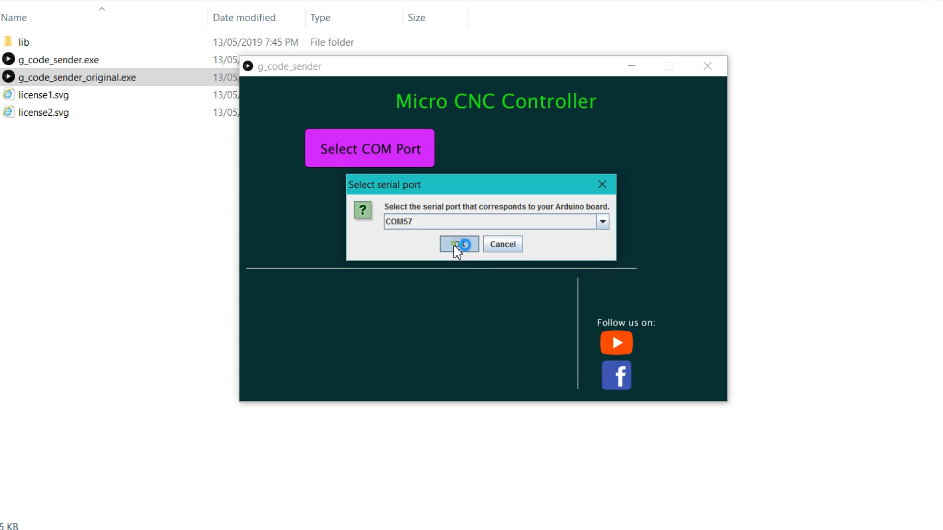
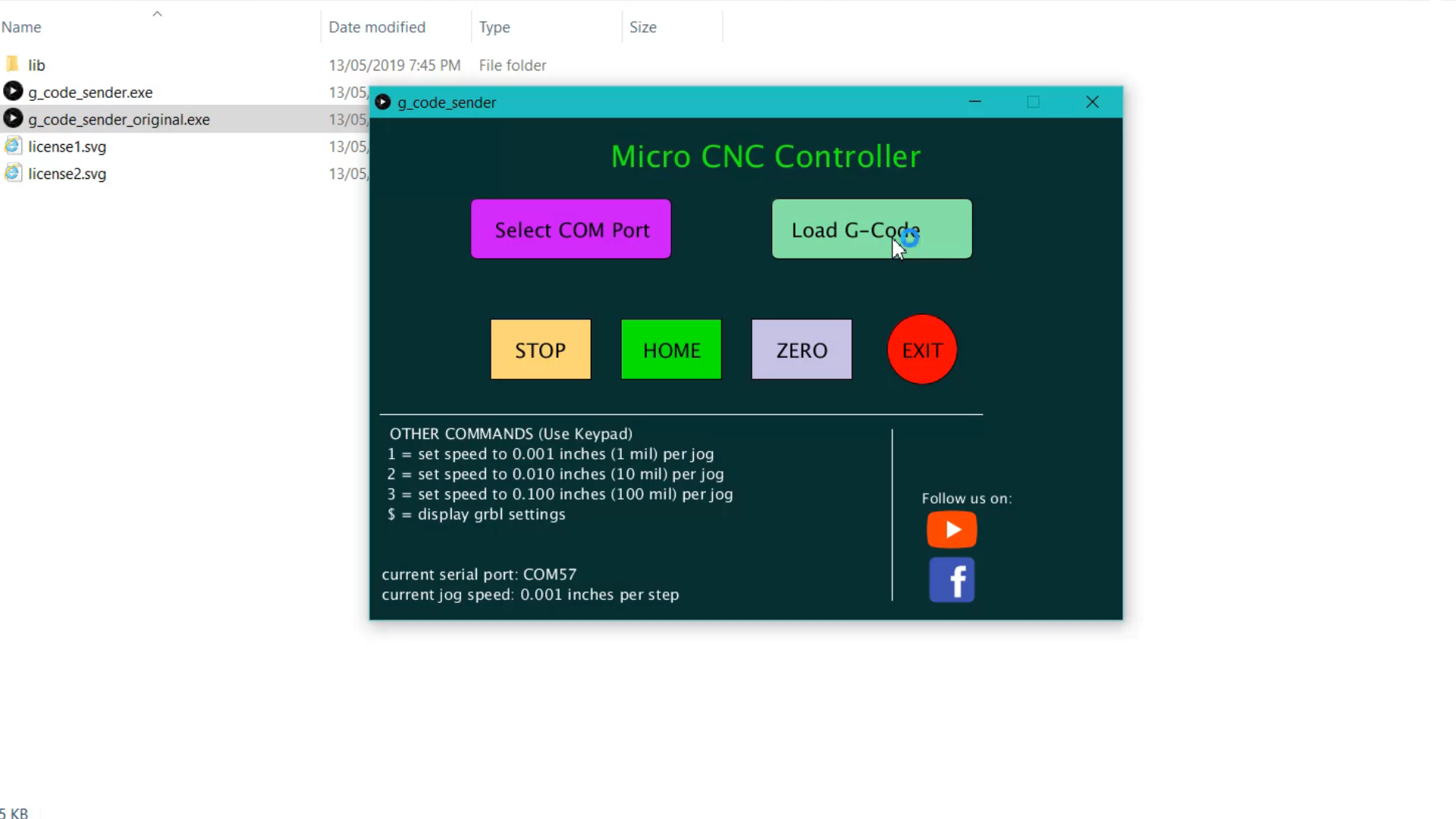
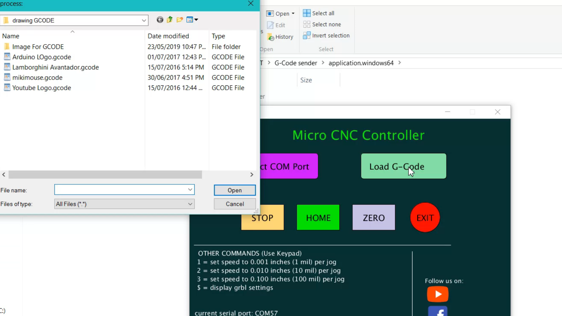
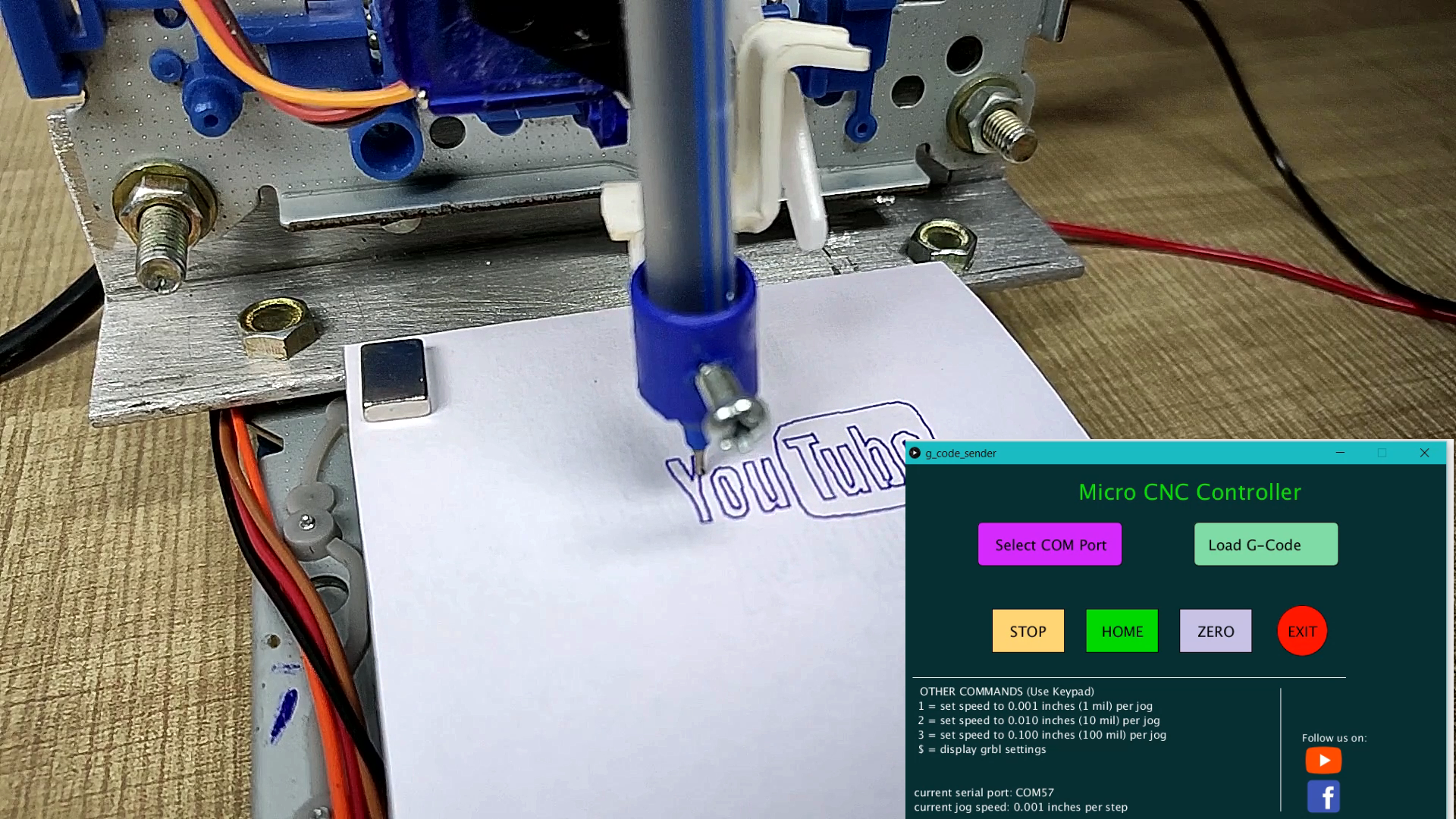
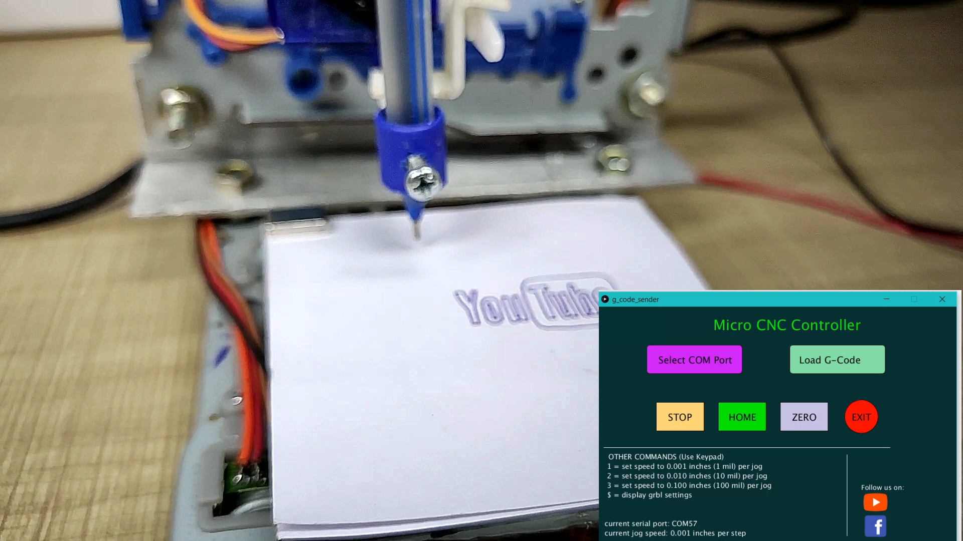
Download the source code and all other required software from the given link. connect Arduino with the computer open the Arduino code from the downloaded file. select the correct COM port and board type from the tool menu and hit upload. after successfully uploading of the program open the G code Sender EXE select correct COM port after selecting COM port all options in the application will open. now click load G-code button to select your file which you want to draw.
Fixing Problems Like Mirror Image Output
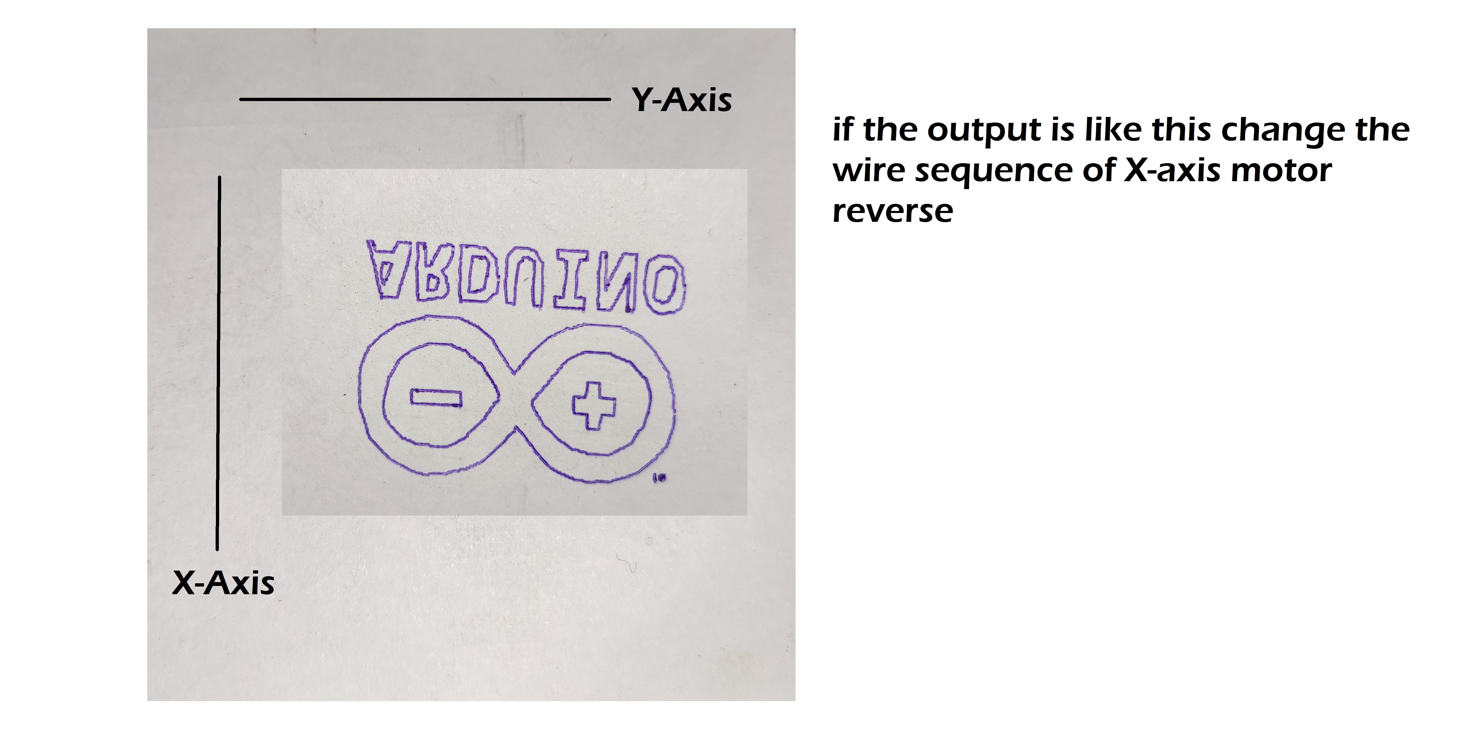
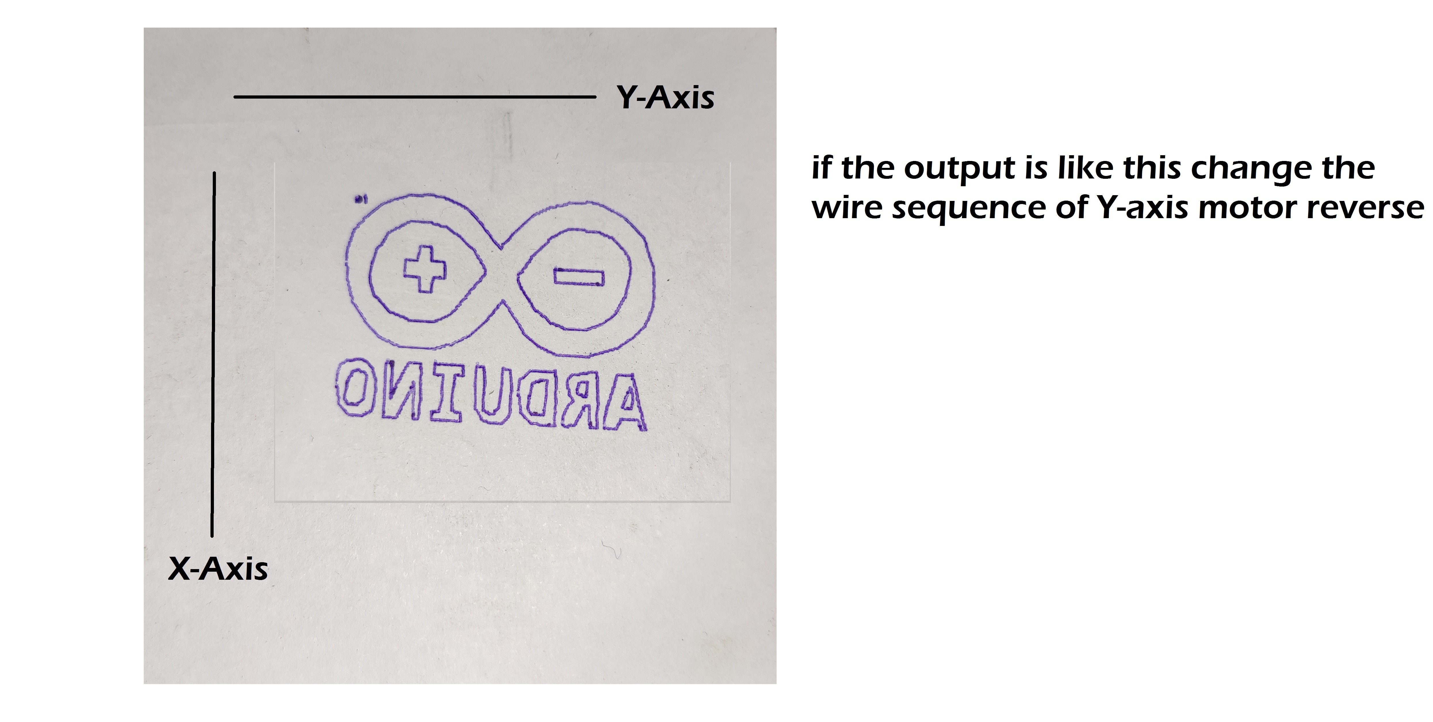
this is very common problem while making these types of machines. if you get mirror image on output, check on which axis it has mirror effect. see pictures.
How to Make G-code ?
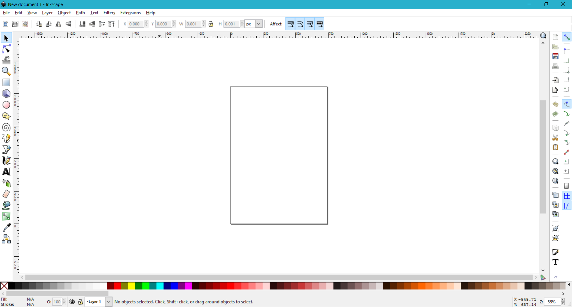
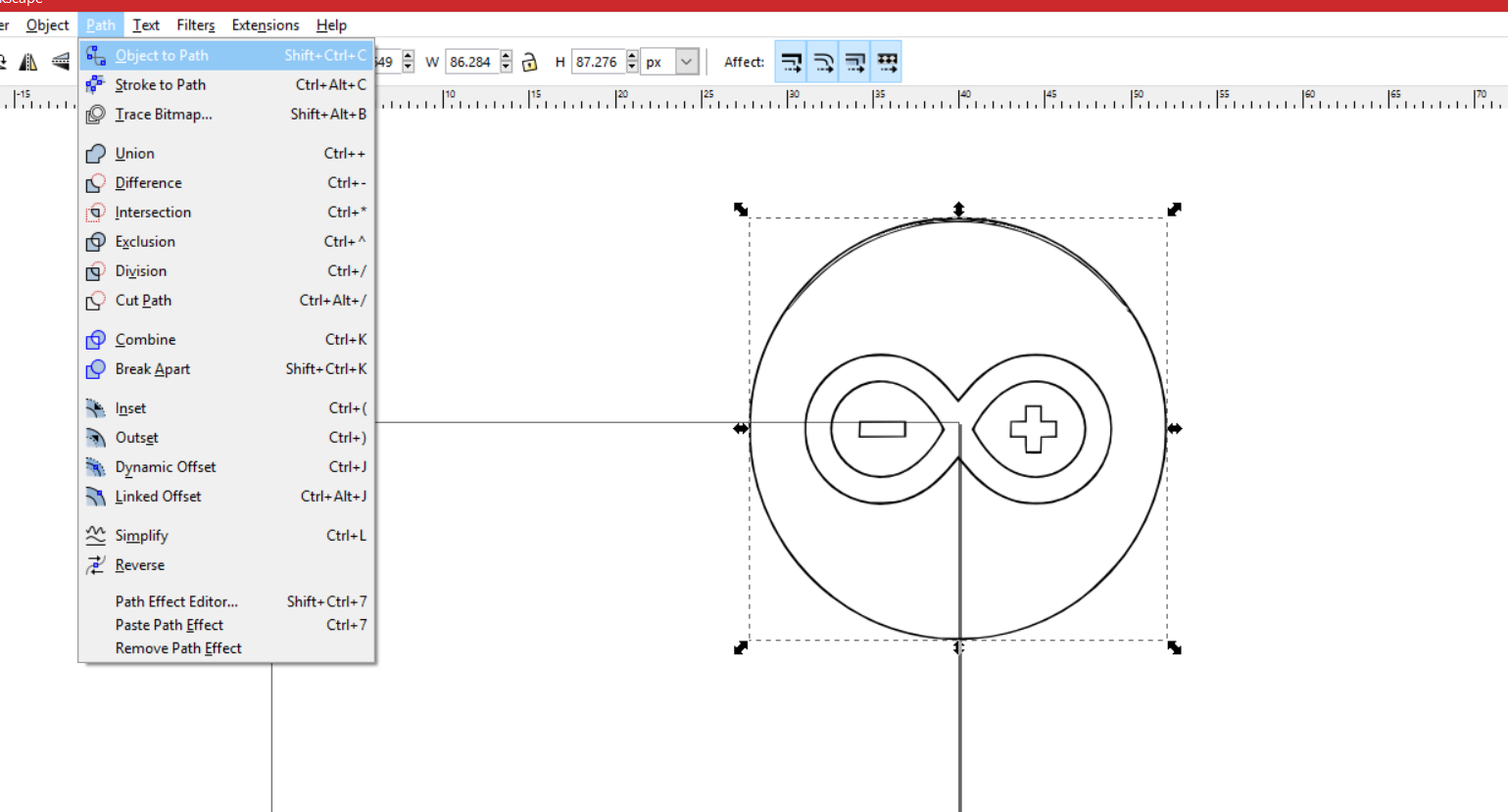
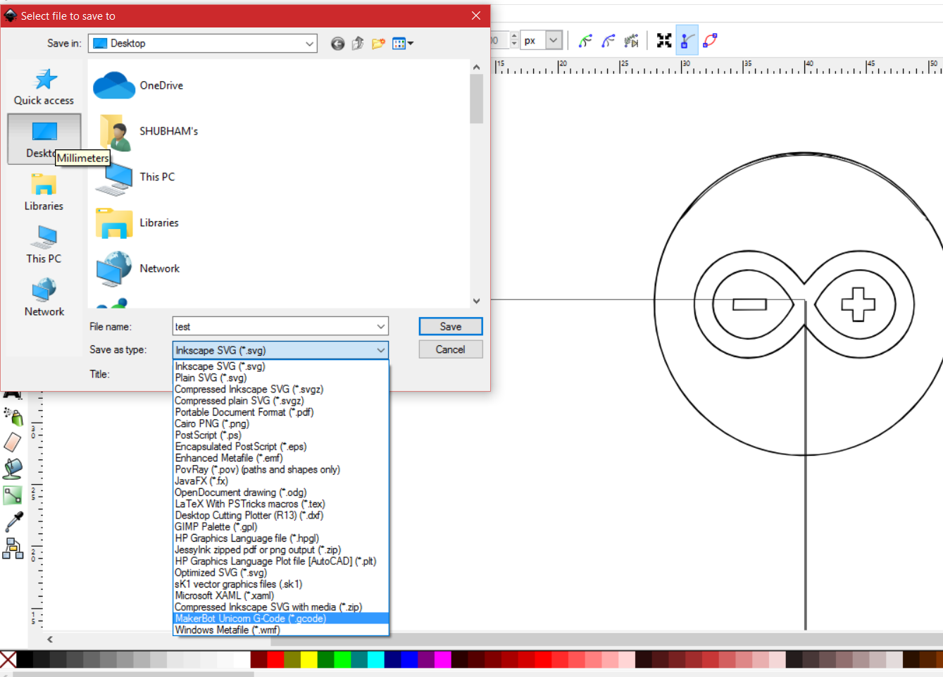
to draw something using this CNC machine we need the G-code. so if I want to make a drawing of a car I need to convert that car image (JPG or PNG) into G-code. to convert or make G-code of something we need Inkscape software. I provide Inkscape software in the Micro CNC Data zip. install Inkscape after installing Inkscape you need to install extension for saving G-code. to do this open the folder Inkscape-unicorn-master from Micro CNC Data zip. Copy All the contents of `src/` folder and pest them to your Inkscape `extensions/` folder.
Typical locations include:
* Windows - `C:\Program Files\Inkscape\share\extensions`
* OS X - `/Applications/Inkscape.app/Contents/Resources/extensions`
* Linux - `/usr/share/Inkscape/extensions`
after installing all things, software is ready to make G-code
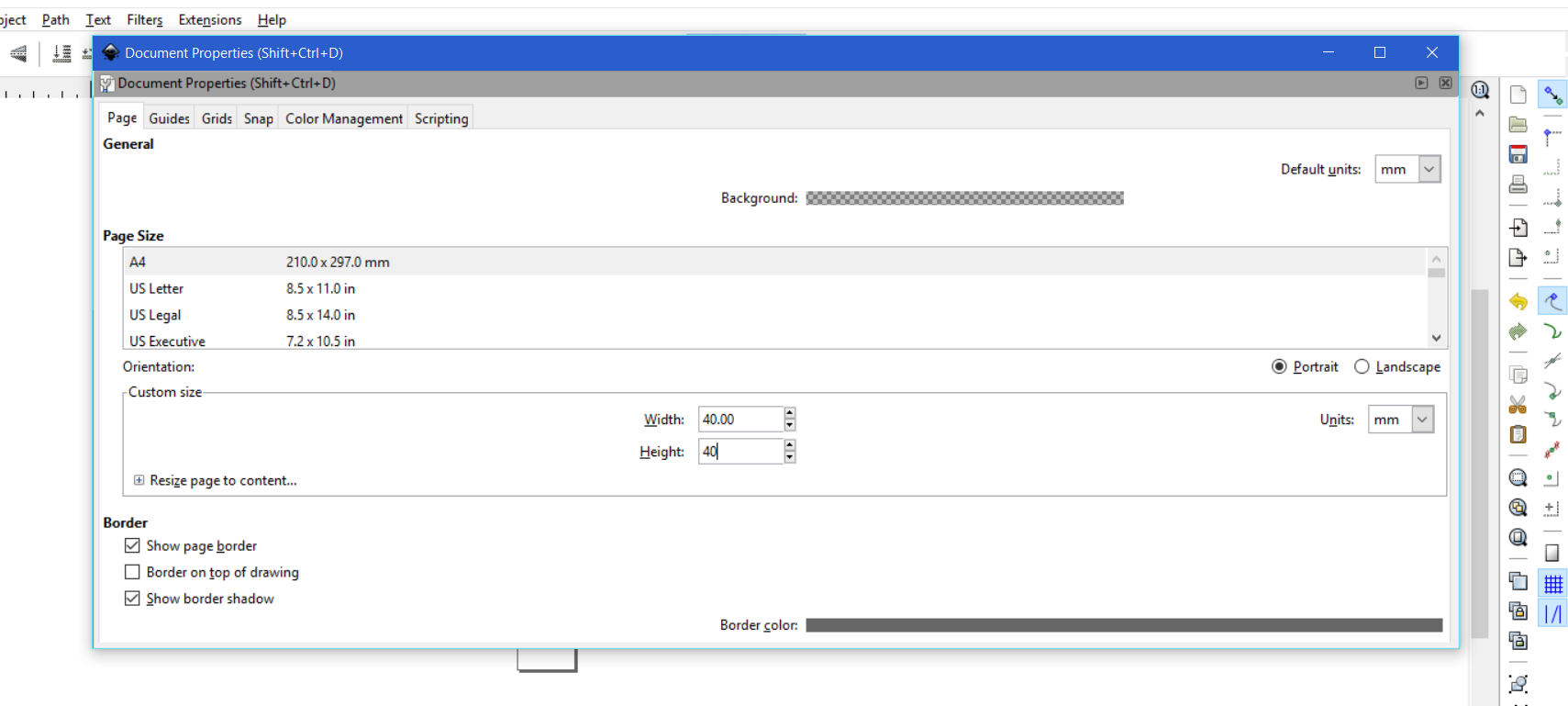
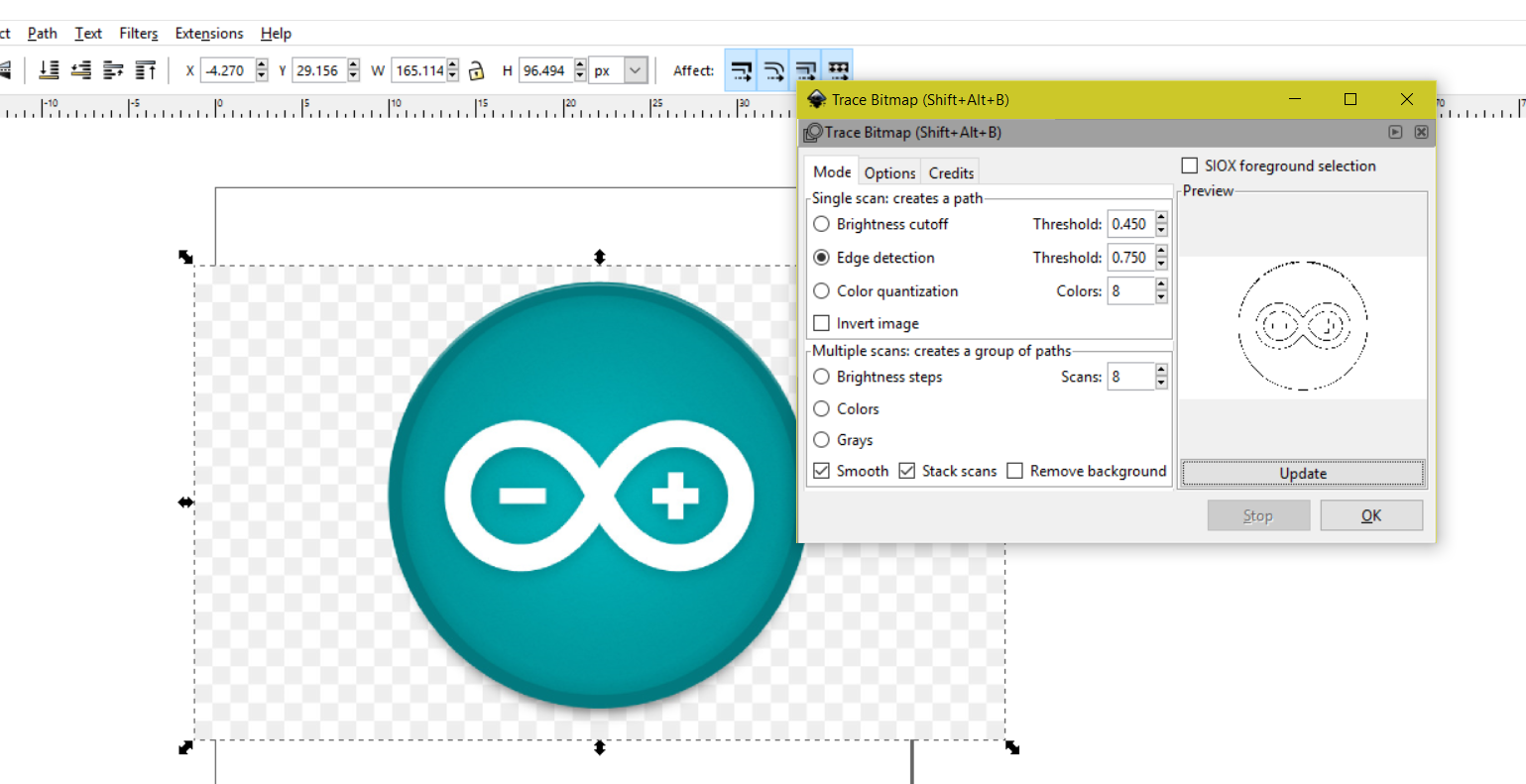
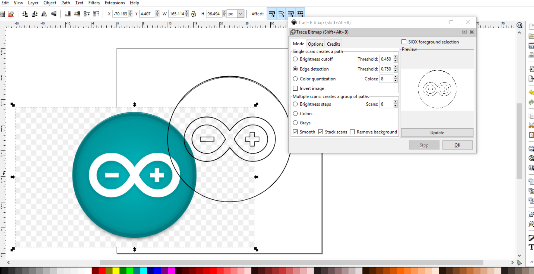
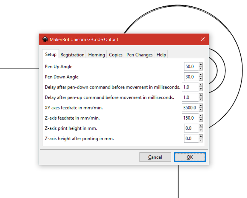
open Inkscape goto file/document property it will pop-ups a new window set all units in mm here, and set width = 40 and height=40 in size and close the window. Now drag the target image and scale down it so it will fit in the output area. now select the image goto the path tab click on trace bitmap. new window will open, select edge detection click update click ok. it will create a duplicate shape of original image. delete the original image. Now place this new image on the top right corner in such a way that the top right corner of output area will be the center of target image. select new image goto path tab click object to path again goto path tab click Dynamic Offset. now goto file/ save As, type file name select save as type = MakerBot Unicorn G-code and click save, new window will open check all the parameters and if not same set them as shown in the picture. click ok and your G-code is ready to load in G-code sender.
Output
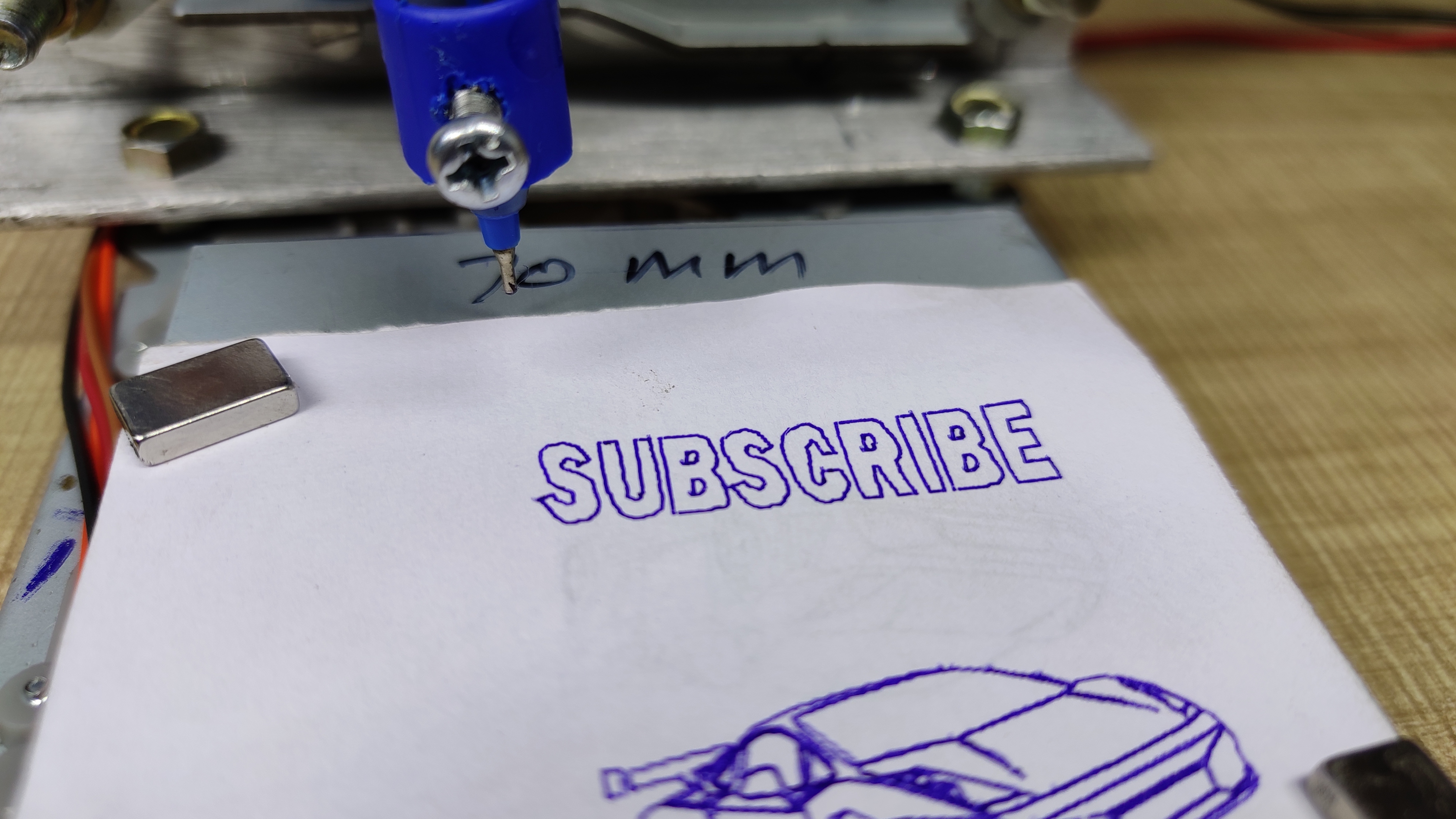
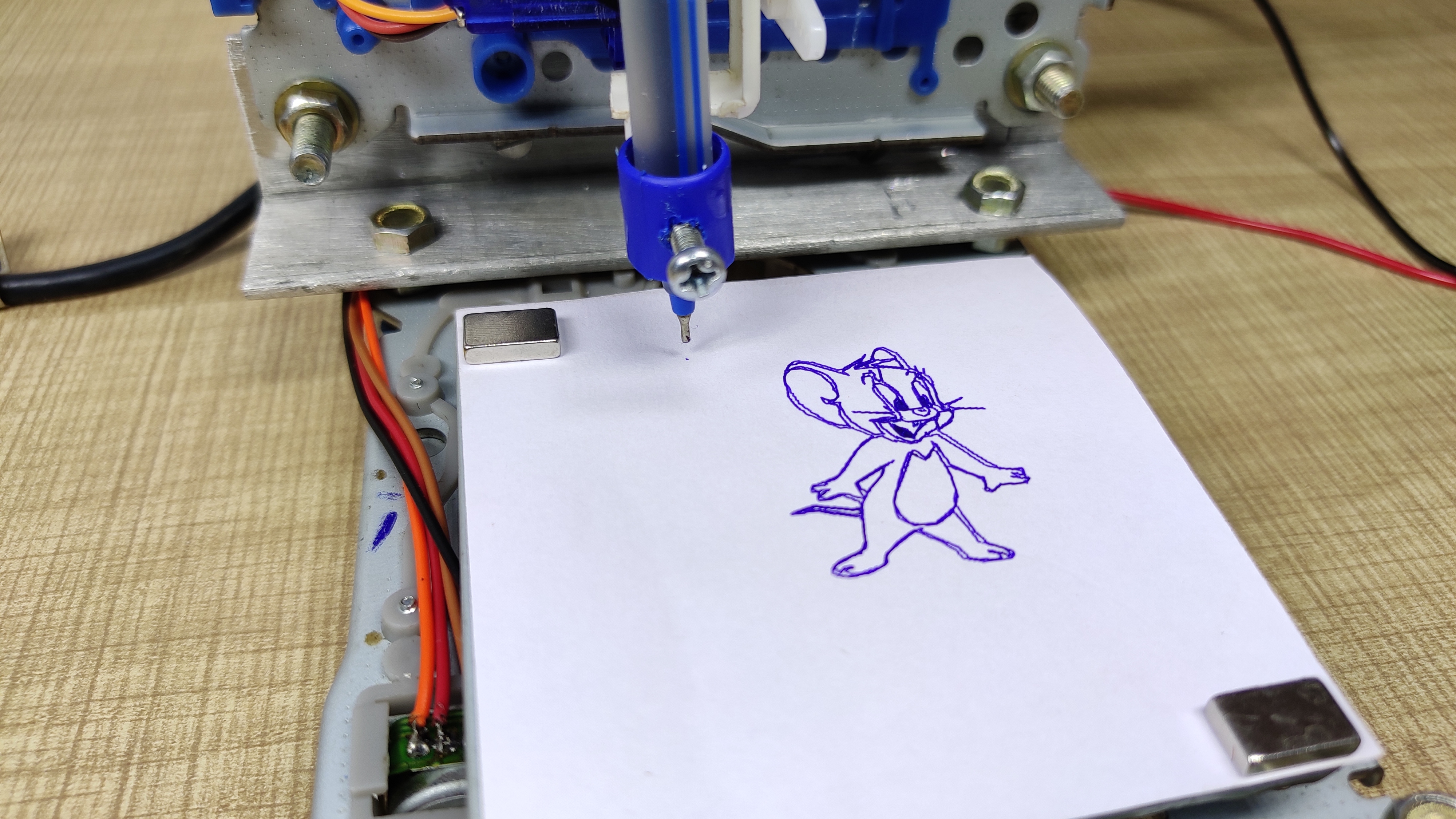
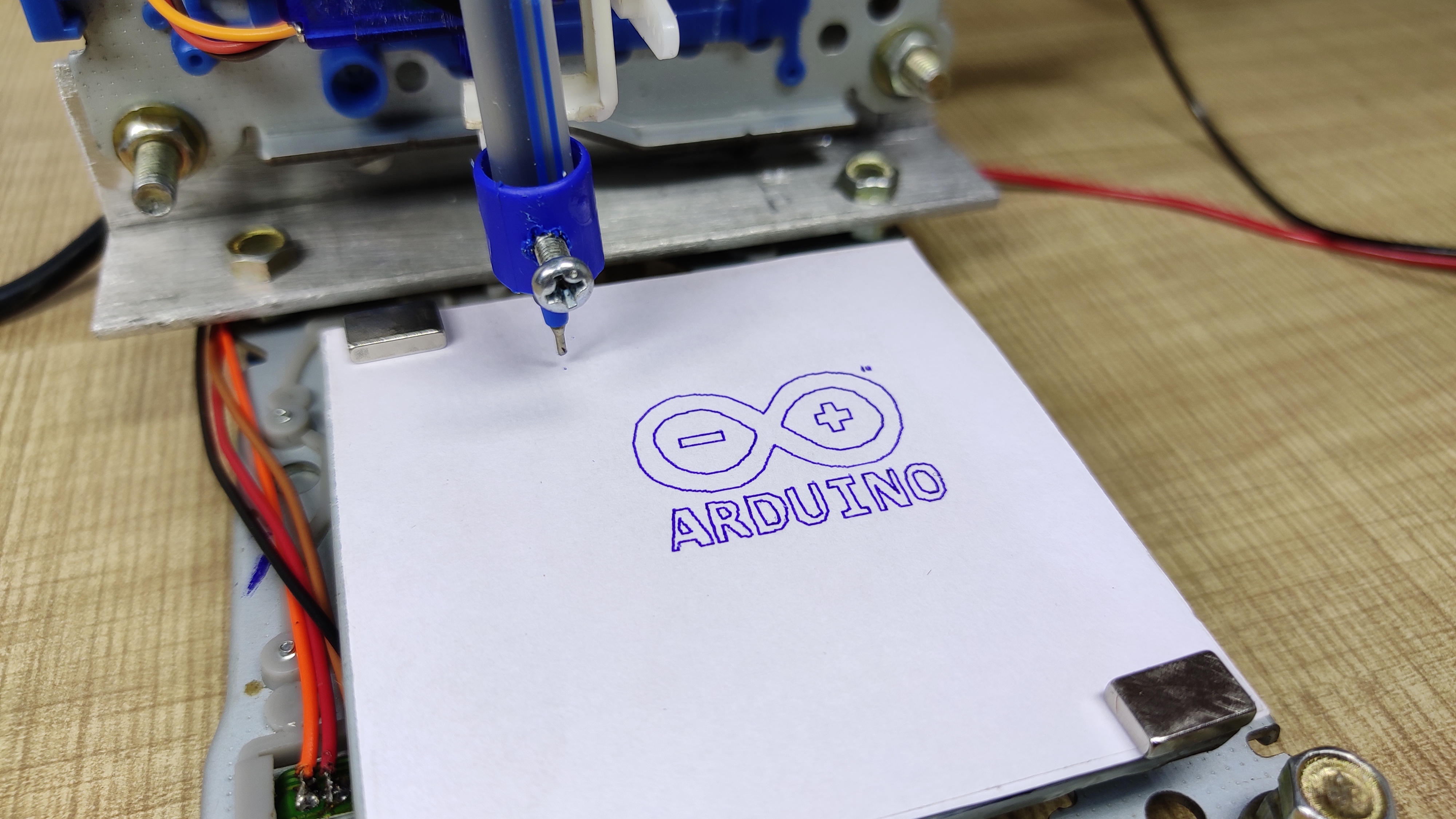
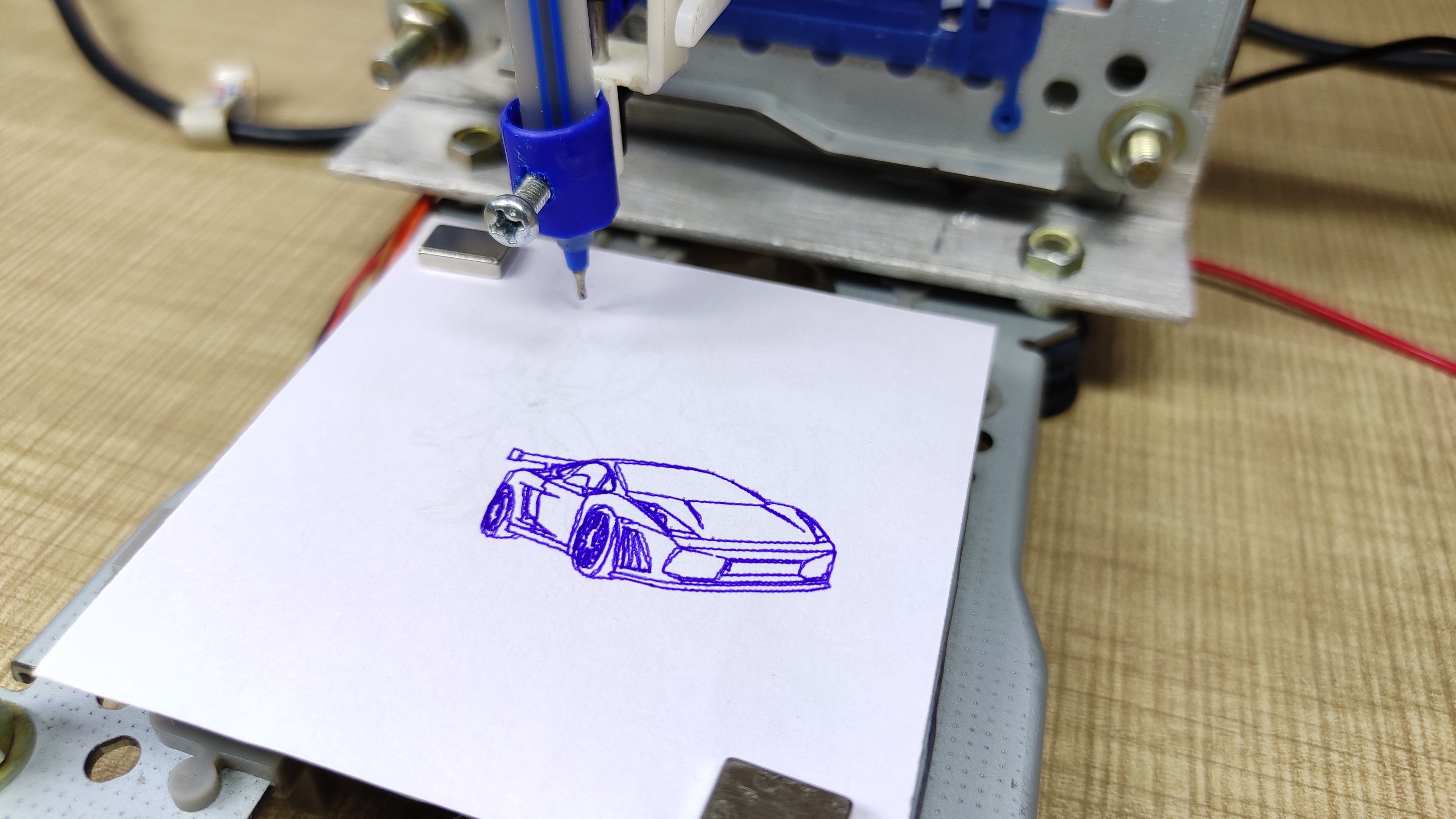
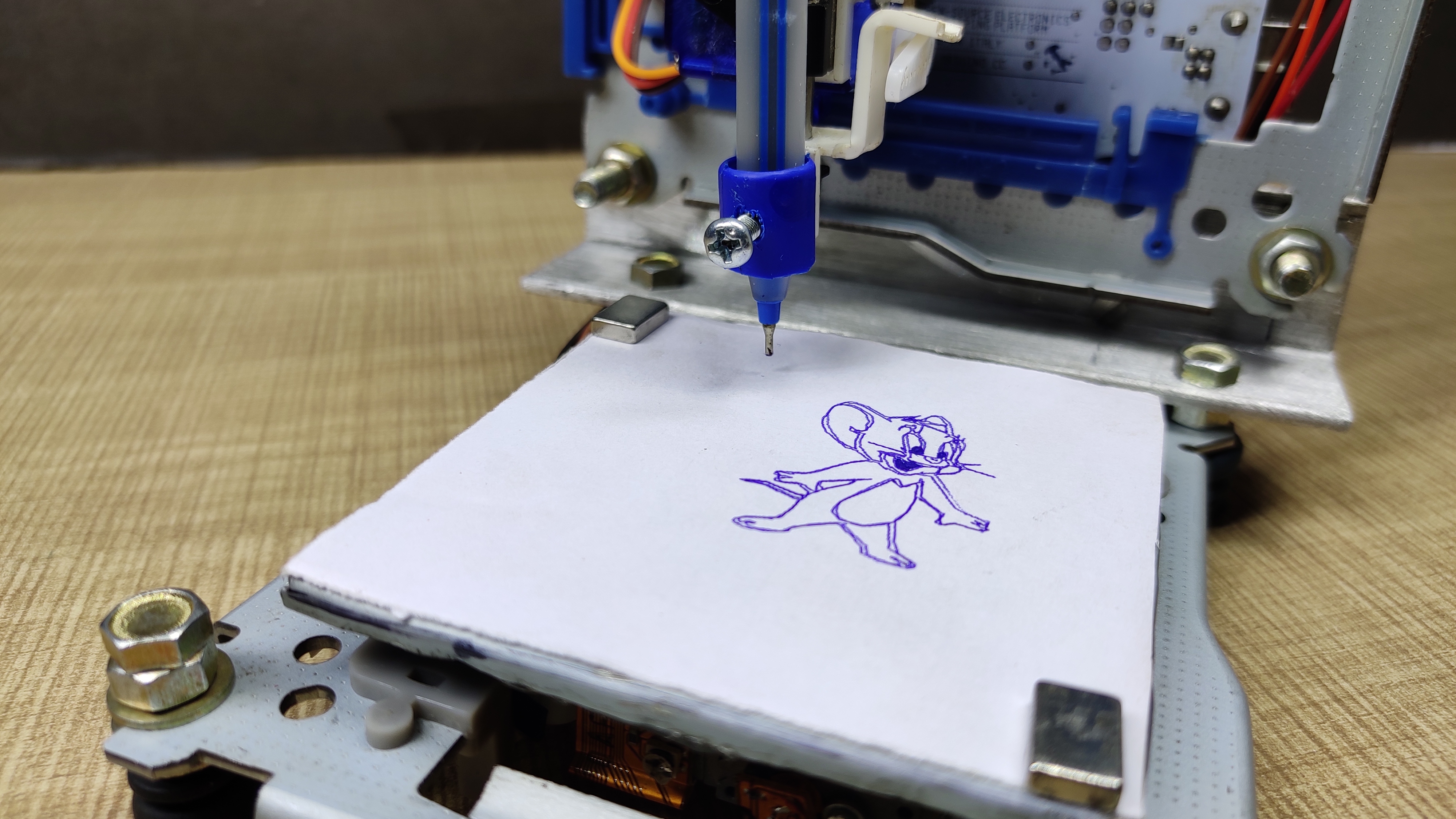
Hope you find this useful. if yes, like it, share it, comment your doubt. For more such projects, follow me! Support my Work and Subscribe to My Channel on YouTube.
Thank you!