How to Make Ernie
by SoundFollowingRobot in Circuits > Microcontrollers
808 Views, 1 Favorites, 0 Comments
How to Make Ernie
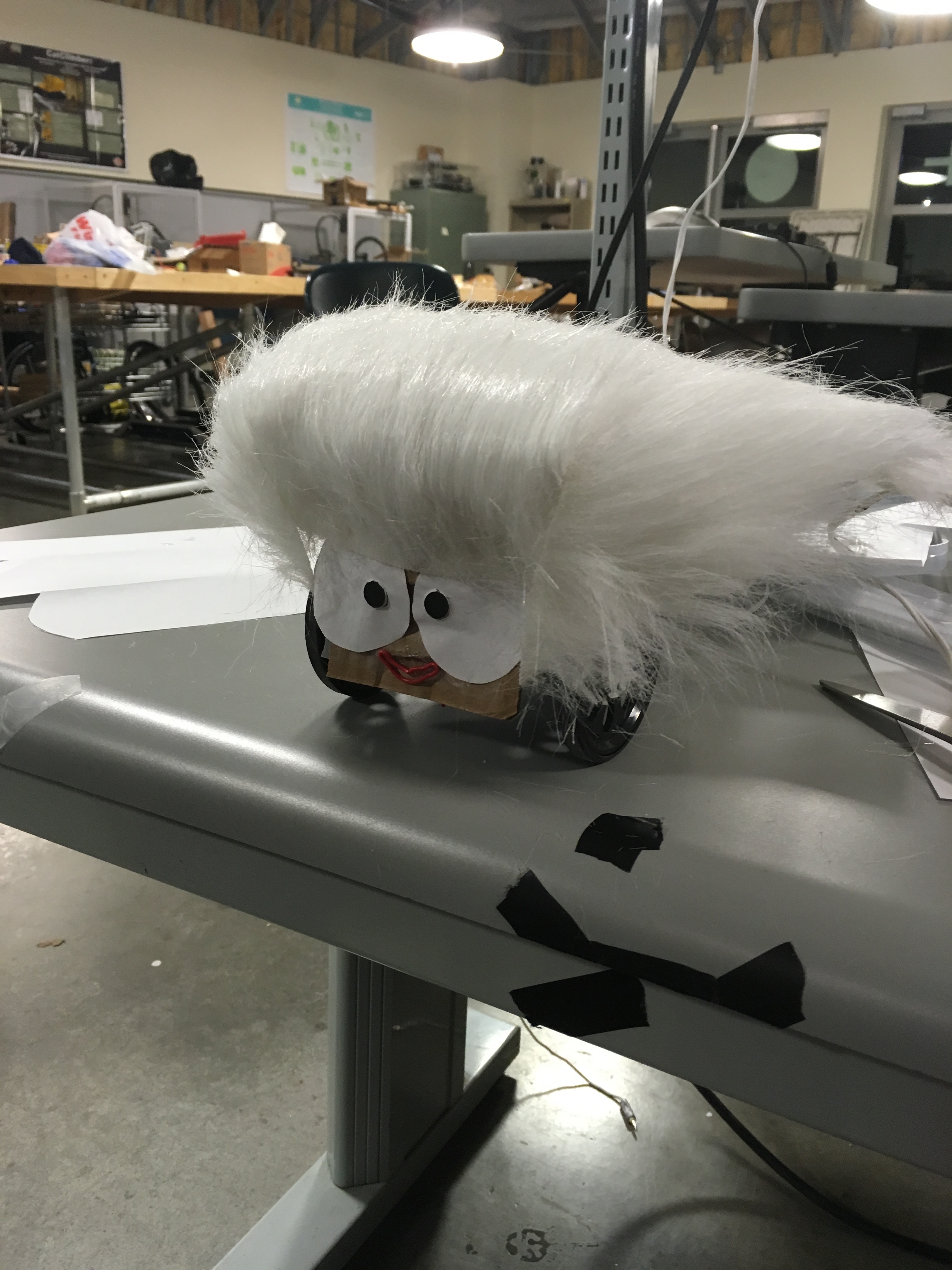
This is a tutorial on how to build Ernie, your autonomous sound following robot, using a Zybo Board. It will cover how to: create a project in Vivado, create PWM-like servo motor drivers in the the FPGA, interface with two sound sensors, create a time difference of arrival IP, use freeRTOS, and run the zybo off a battery pack. This was our final project for a Real Time Operating Systems class (CPE 439) at Cal Poly SLO.
Equipment list:
- 1 - ZYBO Zynq 7000 Development Board
- 2 - Parallax Continuous Rotation Servo
- 2 - Sound Sensor (SparkFun Sound Detector)
- 1 - 5v Lithium Ion USB battery pack (for board)
- 4 - AA batteries (for servos)
- 1 - AA battery pack (w/ 4 battery slots)
- 1 - Micro USB cable
- 1 - Breadboard
- many - Male to Male Wires
- 1 - Servo chassis
Software requirements:
- Xilinx Vivado Design Suite 2016.2
- Digilent Adept 2.16.1
Setting Up a Project in Vivado for Ernie
- A wizard will pop up
- Click Next
- Next name the project
- Never use a project name or directory path that has spaces in it!!!!!
- This will be an RTL project.
- We do not want to specify sources
- Clicking Next, we get to the Part page. We are using a ZYNQ XC7Z010-1CLG400C.
- Vivado doesn’t have the Zybo listed as one of it’s pre-defined boards. Select: “parts” then search for xc7z010clg400-1.
- If you choose the wrong part by mistake you can easily switch chips: Tools -> Project Settings -> General and click the dots to the right of “Project Device”
- Click Create Block Design.
- Name it design_1 for now
- You will see a green bar that says Add IP, click it.
- Search for Zynq.
- Double click ZYNQ7 Processing System,
- This block will appear in our block design.
- You will see a green bar that says Run Block Automation, click it.
- Download zybo_zynq_def.xml below.
- In Vivado, click “Import XPS Settings” and select “zybo_zynq_def.xml”
- This pre populates the Vivado block configuration with all of Zybo board’s built-in peripherals and pin assignments.
- Double click on the ZYNQ block.
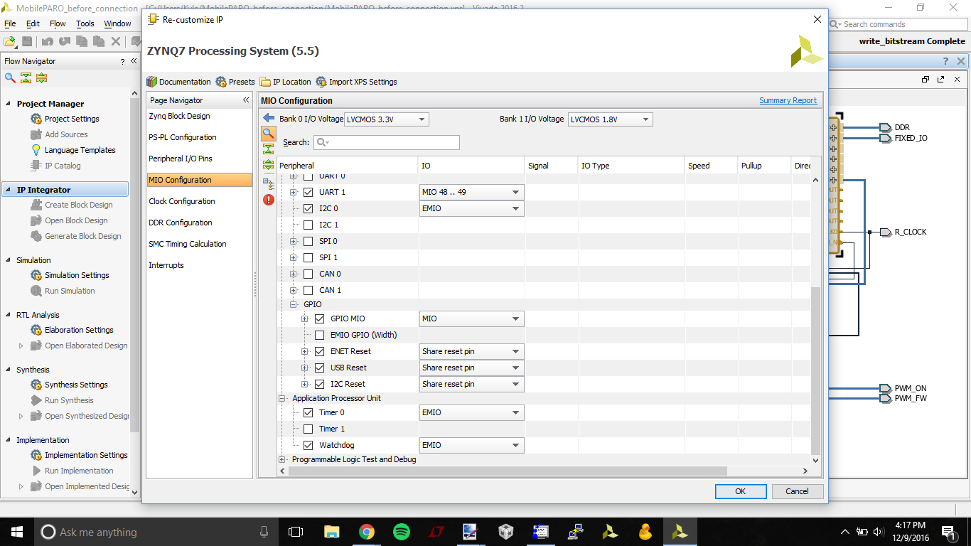
- MIO Configuration
- Enable Timer 0 (under Application Processor Unit - img 1)
- Enable Watchdog (under Application Processor Unit- img 1)
- Enable GPIO->GPIO MIO (under Application Processor Unit - img 2)
- Enable GPIO->ENET Reset (under I/O Peripherals- img 2)
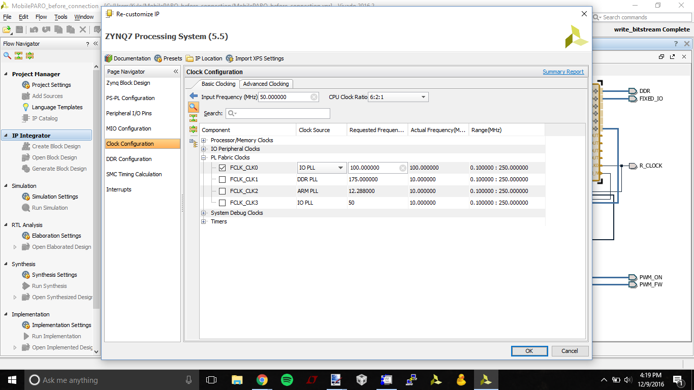
- Clock Configuration
- Disable FCLK0 (under PL Fabric Clocks - img 3)
- MIO Configuration
- Click Ok.
- “Run Block Automation” now.
- There will be some questions about signals, say OK
- Click “Generate HDL Wrapper”.
- We will want to copy the generated wrapper to allow user edits.
- Click OK.
Downloads
Creating Ernie's PWM in Vivado
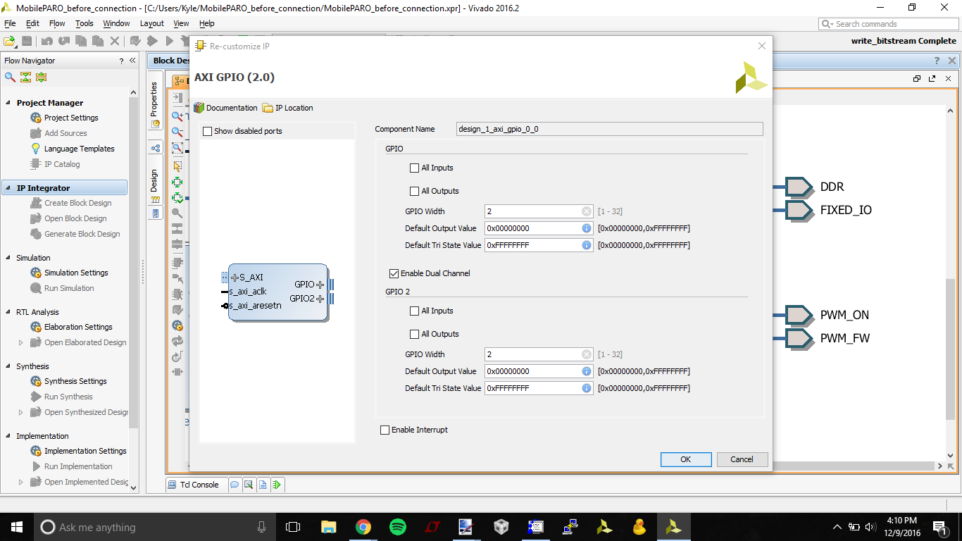
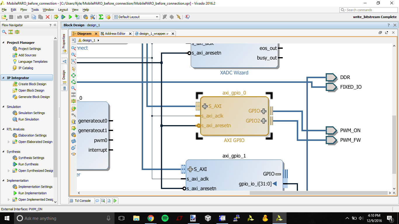
This step will generate a PWM IP with inputs sent via the AXI library.
- Create AXI GPIO block by right-clicking the background, and clicking "add IP"
- type "AXI_GPIO" into the search bar, and select this package
- Re-customize IP by double-clicking the new axi_gpio_0 block
- under GPIO, set GPIO width to 2. These bits will be the PWM_ON signal to drive each PWM module instance.
- click "enable dual channel"
- under GPIO 2, set GPIO width to 2. These bits will be the PWM_FW signal to set the direction of each PWM module instance.
- Right click on the axi_gpio_0 output port labeled GPIO, and select "Make External"
- Click on the new output labeled GPIO, and navigate to the "properties" tab on the left toolbar, and change the name to PWM_ON
- Click on the new output labeled GPIO2, and navigate to the "properties" tab on the left toolbar, and change the name to PWM_FW
- Select Run Connection Automation in the green banner above the block diagram.
- If you manually connect the ports, AXI addresses may not be configured, leading to communication issues later on
- In the Flow Navigator Pane, select project manager -> Add Sources to create a new custom IP block
- choose "add or create design sources", and hit next
- click "create file", change file type to "SystemVerilog", and type "pwm" into the file name field, then click OK
- click Finish
- ignore the Define Module window by pressing OK (we will overwrite these later)
- if it asks if you're sure, click Yes
- In the sources tab, double-click the pwm.sv (located in "Design Sources/design_1_wrapper")
- Copy/paste the entire SystemVerilog code from the pwm.txt file attached below
Downloads
Creating Ernie's TDOA in Vivado
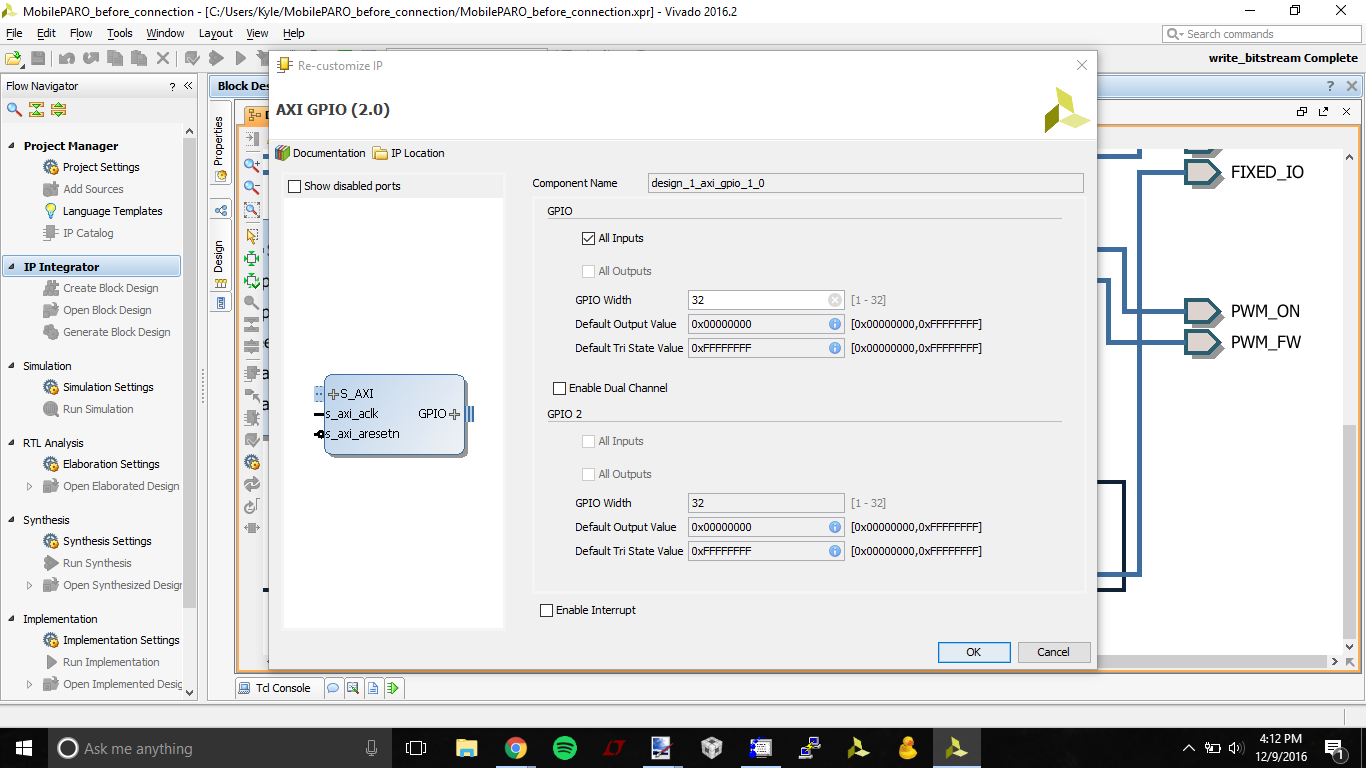
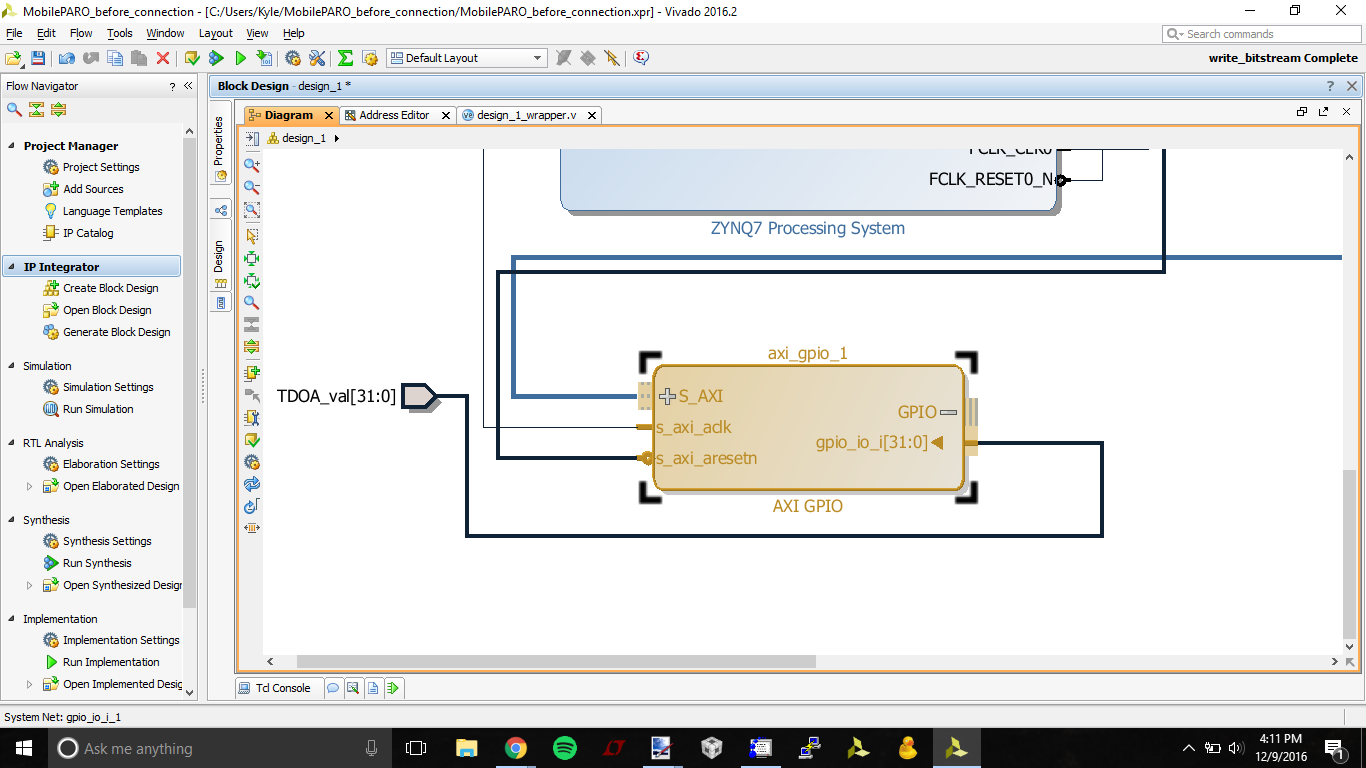
This step will generate a TDOA IP whose output can be read via the AXI library
- Create AXI GPIO block by right-clicking the background, and clicking "add IP"
- type "AXI_GPIO" into the search bar, and select this package
- Re-customize IP by double-clicking the new axi_gpio_1 block
- under GPIO, check the "All Inputs" box, and set GPIO width to 32. This bus will be the time difference of arrival between the two sensors.
- inside the axi_gpio_1 block, click the + next to the GPIO port to reveal gpio_io_i[31:0].
- Right click on the axi_gpio_1 output port labeled gpio_io_i[31:0], and select "Make External"
- Click on the new input labeled gpio_io_i[31:0], and navigate to the "properties" tab on the left toolbar, and change the name to TDOA_val
- Select Run Connection Automation in the green banner above the block diagram.
- If you manually connect the ports, AXI addresses may not be configured, leading to communication issues later on
- In the Flow Navigator Pane, select project manager -> Add Sources to create a new custom IP block
- choose "add or create design sources", and hit next
- click "create file", change file type to "SystemVerilog", and type "tdoa" into the file name field, then click OK
- click Finish
- ignore the Define Module window by pressing OK (we will overwrite these later)
- if it asks if you're sure, click Yes
- In the sources tab, double-click the tdoa.sv (located in "Design Sources/design_1_wrapper")
- Copy/paste the entire SystemVerilog code from the tdoa.txt file attached below
Downloads
Wrapping and Exporting Ernie
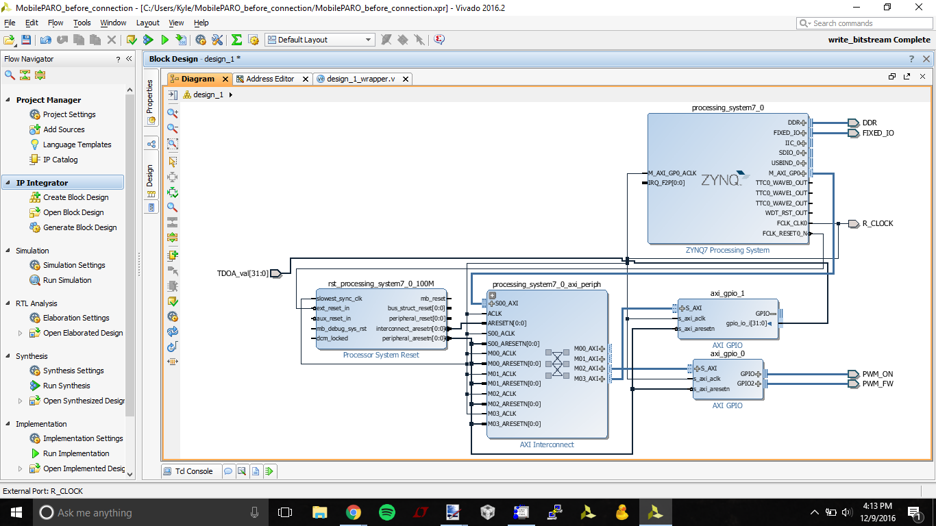
- Verify that the block diagram looks like the screenshot attached
- In the sources tab, right-click design_1.bd and select "Create HDL Wrapper..."
- Select "Copy generated output to allow user edits", then press "OK"
- Copy the code from design_1_wrapper.txt attached below, and paste it in place of the generated design_1_wrapper.v code
- save design_1_wrapper.v
- In the sources tab, double-click the ZYBO_Master.xdc file under Constraints/constrs1
- Copy the code from ZYBO_Master.txt attached below, and paste it in place of the existing ZYBO_Master.xdc code
- Note the following input/output pins:
- L15: PWM signal for the left motor (Pmod JA2 on the Zybo)
- L14: PWM signal for the right motor (Pmod JA8 on the Zybo)
- V12: gate input from sound sensor 1 (Pmod JE1 on the Zybo)
- K16: gate input from sound sensor 2 (Pmod JE2 on the Zybo)
- In the Flow Navigator Pane, Click "Generate Bitstream" under Program and Debug
- if you think it's done right away, it's probably not. seriously, make some tea
- Click File->Export->Generate Hardware
- Check "Include Bitstream" and hit OK
- Click File-> Launch SDK
Building Ernie
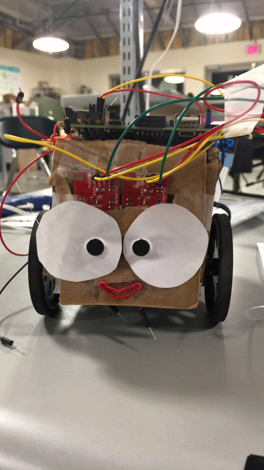
- Mount the servos to the servo chassis.
- Following the datasheet for the servos, do the following:
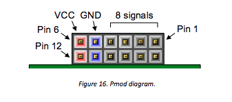
- connect the ground of the servos to ground pins on the Zybo's JA Pmod (see attached pinout image)
- connect the power pin of the servos to the AA battery pack
- We found that when the servos are connected to the Zybo's Vdd, the board draws too much current, causing the board to continuously reset.
- connect the input signal pins to the Zybo's appropriate output pins (left: JA2, right: JA8)
- mount the sound sensors to the front of the chassis, facing forward, keeping them as close together as possible
- use the sound sensor's hookup guide to integrate the sound sensors
- wire the ground and Vdd pins of each sound sensor to the ground and Vdd pins on the Zybo's JE Pmod (see attached pinout image)
- wire the left sound sensor's Gate pin to JE1
- wire the right sound sensor's Gate pin to JE2
Downloads
Ernie's First BSP
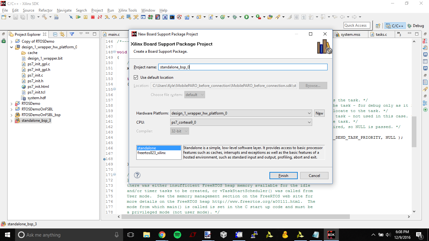
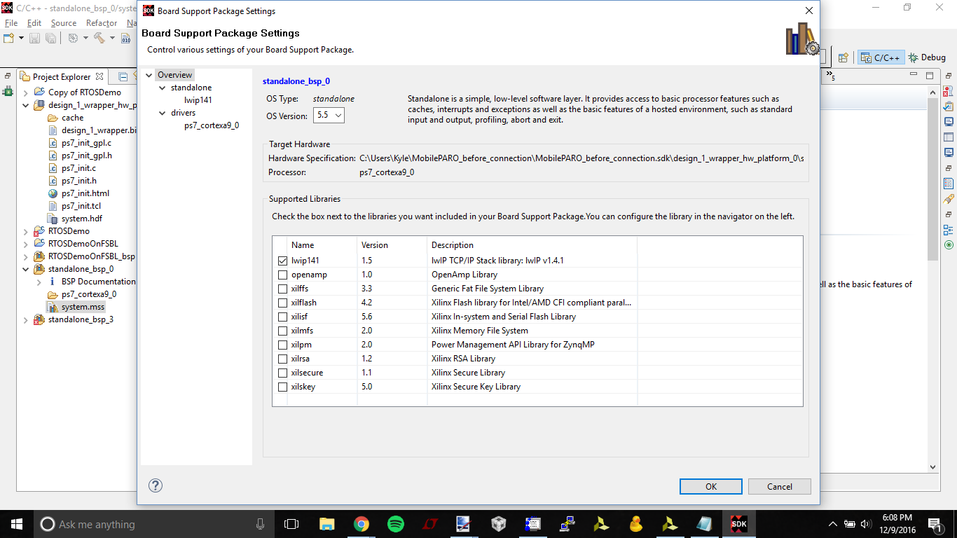
- Create a BSP to wrap up the platform we just created.
- You can get this through File -> New -> Board Support Package.
- A wizard will pop up to help you create the BSP.
- We want to tie this BSP with our Platform that we just created, so
- Hardware Platform should line up with the one we just created (see img 1)
- Our CPU will be the _0 CPU.
- Click Finish
- Be sure to check off lwip141 for inclusion with your bsp in the window that pops up (see img 2)
FreeRTOS'ing Ernie
- Download the latest FreeRTOS release from Sourceforge.
- If the download is an executable, run it to extract the FreeRTOS files into your project directory.
- Keep that SDK open, and click File -> Import.
- We want to click General->From an Existing Workspace, and then we will want to navigate to where we downloaded FreeRTOS.
- Our demo will be located in FreeRTOS/Demo/CORTEX_A9_Zynq_ZC702. Upon selecting this folder, we should see three projects pop up (our code (OS), it’s BSP, and the HW Platform).
- ONLY Import RTOSDemo into your current workspace.
- On all “blue” folder projects change the referenced BSP
- Right clicking and selecting “Change Referenced BSP.”
- Select the BSP you just created for your Zybo
- Code Editing in Xilinx’s SDK Blue folders are the actual code projects.
Importing Ernie's C Code
- In the RTOSDemo/src directory, overwrite the existing main.c with the main.c file attached here.
- Copy the main_sound.c fiile into the RTOSDemo/src directory.
Debugging Ernie
- Select Run -> Debug Configurations
- On the left pane create a new System Debugger run
- In the Target Setup tab,
- select “Reset Entire System” so that the both that and ps7_init are selected
- Now select the Application tab.
- Select “download application”
- Set the cortexa9_0 core to “stop at program entry”
- Click Apply and Debug.
- Verify that there are no errors in the debugging process
- Keeping a close watch on the robot, press the Resume button until program runs without hitting any breakpoints
- The robot should now turn and move towards loud noises. Yay!
Making Ernie Autonomous
- Once your project is all ready to go (you can run with no problems through the debugger) you are ready to load it to the flash memory on your board.
- Create what is called the “first stage boot loader” (FSBL) project and contains all the instruction that your board will need in order to load your project files (the bit stream and OS) on startup.
- Select: File->New->Application Project and the following window should appear.
- Name it what you want (i.e. “FSBL”)
- Ensure the hardware platform is the one you are working with
- Press next (Do not press Finish)
- Select the Zynq FSBL template
- Click finish.
- Once the creation process is complete you will know if everything worked if you see the following two new folders in the Project Explorer window.
- Create a Boot Image Now you will need to create the Boot image.
- Right click on your project folder (in this case mine is called “RTOSDemo”)
- Click “Create Boot image” from the drop down
- If everything is linked correctly, the project will know what files it needs and the following window will look as you see below (key being that you have 3 partitions under Boot image section, the bootloader, your bit file, and your projects .elf file).
- If this is not the case there is possibly something wrong with your project linking. Insure that the project folders are linked to their respective BSPs
- Click the “Create Image” button
- The last step to perform in software is to now flash your previously created image to the board’s memory
- Select from the SDK’s main tool bar select Xilinx Tools->Program Flash Memory
- Insure that the correct hardware platform is selected and that the image file path is correctly pointing to the .BIN file created in the previous step.
- Select “qspi single“ from the Flash type
- Tick the “Verify after flash” to insure the integrity but it is not needed
- Configure Your Board Lastly you need to insure that the boards programming mode jumper (JP5) is correctly set to select to boot from the qspi (which contains what you just flashed) when the BootROM is run.
- Now simply power cycle the device and insure the “Logic Configuration Done LED” (LED 10) is lit green.
Making Ernie Cute
- Fur
- Lots of Fur
- BIG eyes!
- ... top hat