How to Interface 16×2 LCD With Arduino Uno
by Rachana Jain in Circuits > Arduino
1466 Views, 2 Favorites, 0 Comments
How to Interface 16×2 LCD With Arduino Uno

A 16x2 LCD (Liquid Crystal Display) is commonly used in electronics projects for displaying sensor readings, messages, or real-time data.
In this project, we will interface a 16x2 LCD module with an Arduino Uno and display a custom message
Supplies
- Arduino Uno
- 16x2 LCD Display
- Potentiometer (10KΩ) for contrast control
- Resistor (220Ω)
- Breadboard & Jumper Wires
What Is a 16×2 LCD Module?
A 16×2 LCD module is a widely used Liquid Crystal Display (LCD) that can show 16 characters per line on 2 lines, making it ideal for displaying text and simple symbols in embedded systems and microcontroller-based projects.
Key Features
- LCD displays up to 32 characters at a time.
- Most 16×2 LCDs use the Hitachi HD44780 driver, making them easy to interface with microcontrollers like Arduino, STM32, and Raspberry Pi.
- It operates in 4-bit or 8-bit modes, requiring 4 or 8 data lines for communication.
- Many LCDs include an LED backlight for visibility and a potentiometer to adjust contrast.
- Can be controlled using direct GPIO, I2C, or SPI with an adapter.
16×2 LCD Pinout Diagram

Power and Control Pins:
- GND (Ground) – Connect this pin to the ground (0V) of the power supply.
- VCC (Power Supply) – Provides power to the LCD; typically connected to +5V.
- VO (Contrast Adjustment) – Controls the display contrast. A 10kΩ potentiometer is usually connected between VCC, GND, and VO to adjust the contrast level.
- RS (Register Select) – Used to differentiate command and data:
- RS = 0 → Command mode (for sending instructions like cursor position).
- RS = 1 → Data mode (for sending character data to be displayed).
- R/W (Read/Write) – Selects read or write operation:
- R/W = 0 → Write to LCD (default mode for most applications).
- R/W = 1 → Read from LCD (used to check busy status via D7 pin).
- E (Enable) – Latches data into the LCD when transitioning from HIGH to LOW. The signal must be held HIGH for at least 450ns before going LOW.
Data Pins (D0 to D7):
These 8 pins (D0–D7) are used to send data/commands to the LCD.
- In 8-bit mode: All 8 data pins (D0–D7) are used.
- In 4-bit mode: Only D4 to D7 are used, while D0 to D3 are grounded.
Backlight Pins:
LED (+) (Anode) – Connect to +5V through a 220Ω resistor to power the backlight.
LED (-) (Cathode) – Connect to GND to complete the backlight circuit.
Interfacing LCD With Arduino in 8-bit Mode

In this project, we will interface a 16×2 LCD module with an Arduino UNO in 8-bit mode. This means all 8 data lines (D0–D7) will be used for communication. Instead of checking the busy flag (D7 pin), we will introduce a small delay after each command execution. The R/W pin will be permanently grounded, as we will only write data to the LCD.
Code
Upload the following code to Arduino:
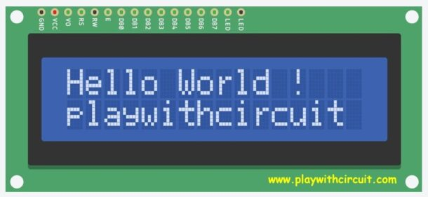
The Output of Code
To learn how to interface LCD with Arduino in 4-bit mode checkout: https://playwithcircuit.com/interfacing-16x2-lcd-with-arduino/