How to Help Others With a Parametrically Assisted Gas Cap Opener!
by Nikhil Ashri in Workshop > 3D Printing
664 Views, 2 Favorites, 0 Comments
How to Help Others With a Parametrically Assisted Gas Cap Opener!
On the MakersMakingChange.com, a website used for assisting in people with certain disabilities and limitations, I decided to parametricize a design for something that I thought was super useful and interesting, a gas can opener to assist people with who have limited mobility and struggle with doing the simple task of filling up the gas can on their car. Though the project seems simple, it can be a life changer and a few hours of my time is able to change days of someone else's time and money. I have recently made other projects that have to do with Bioengineering all focusing on different aspects of engineering. For this project we will be learning how to use Fusion 360 to parametrize a design, and then print it. This project will allow people of various different gas cap dimensions to be able to access such a cool project!
This project was done at Charlotte Latin School.
Supplies
- PrusaSlicer (or any other 3D printer which supports gcode)
- Printing Filament
- Fusion360
- PruserSlicer app (v. 2.5.0)
Setting Up the Model
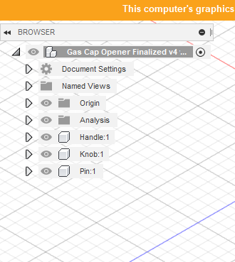
First open Fusion 360, and create a new project. To begin the project, start by creating three components (click "S" and then search for the component feature). Name these components "Pin", "Knob", and "Handle".
Setting Up the Parametrics
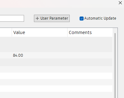
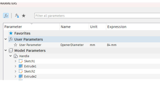
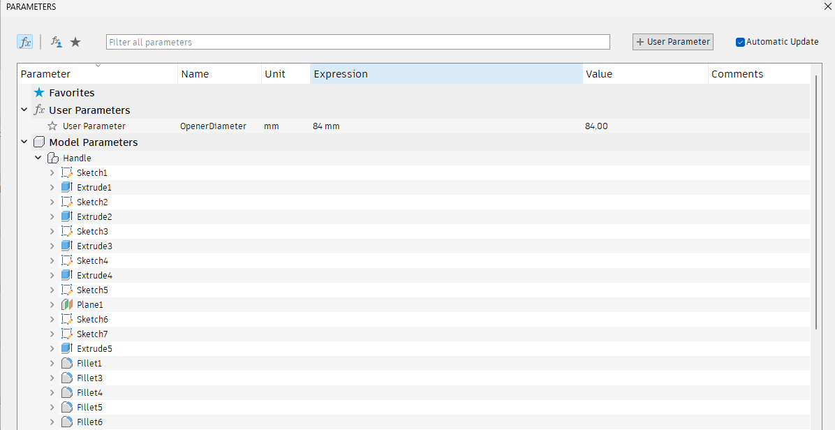
This is probably the most important and novel step in the process! Click "S" on your keyboard and search up "Change Parameters". On the top right of the Parameters menu click on "+User Parameter". Name this Parameter "OpenerDiameter" and set the value to 84 millimeters. This is going to allow us to change the size of the actual opener of the can. When we are completed with the file, you can simply go to the parameters menu to create your design dimensions based on whatever your car needs!
Creating the Base
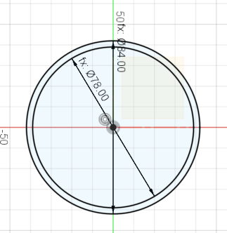
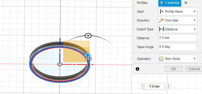
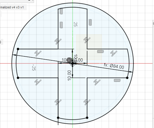
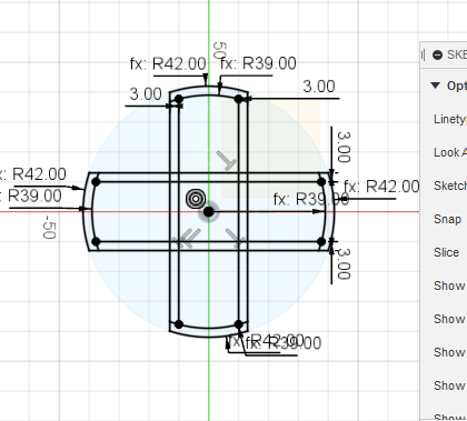
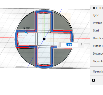
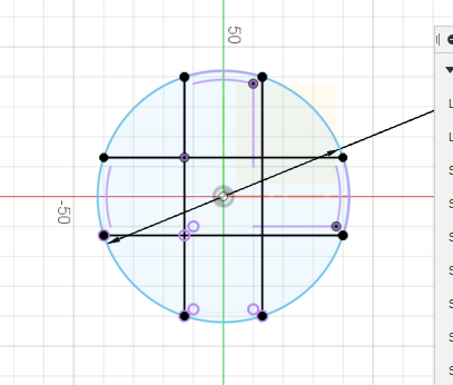
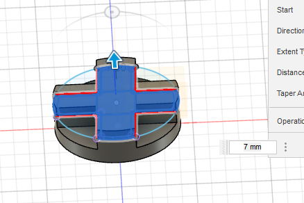
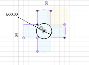
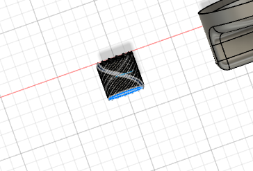
For this step, we are going to build a series of sketches in order to build our base. First, create a sketch, and create a center circle with the diameter of the "OpenerDiameter" parameter. Next, create a new sketch which has a center circle diameter of "OpenerDiameter"-6. Make sure both circles of concentric! Next, to create our next sketch we are first going to extrude the ring created by our original sketch. This extrusion will be 7.5 mm! Building off of this extrusion, we are going to make a new circle of diameter of "OpenerDiameter". After this, we will build 4 line segments each 10 millimeters away in the horizontal direction, and 10 millimeters in the vertical direction from the center (For example one line segment would be 10 mm from the left and 10 mm below the center). A image is shown above. We are then going to create 4 arcs connecting each line segment and each of these arcs have radius dimension ("OpenerDiameter"/2)-3. This is also shown above. You should have a "cross" like figure inside of a circle for this sketch. We are going to extrude the section of the sketch which does not include the cross by 2.5 mm. Then, we are going to build the exact same cross, but also create line segments three centimeters away from each of the line segments. We are then going to connect these farther apart line segments with a arc of radius dimension "OpenerDiameter"/2. This creates a "cross" within a cross (picture above). We are going to extrude the "ring" cross created within both crosses by 9 mm. We are then going to build a final "cross" with the same dimensions as are longer cross we built before the extrusion. Extrude this by 7 mm. Finally, create a center circle of diameter 30 mm.
Creating the Stem
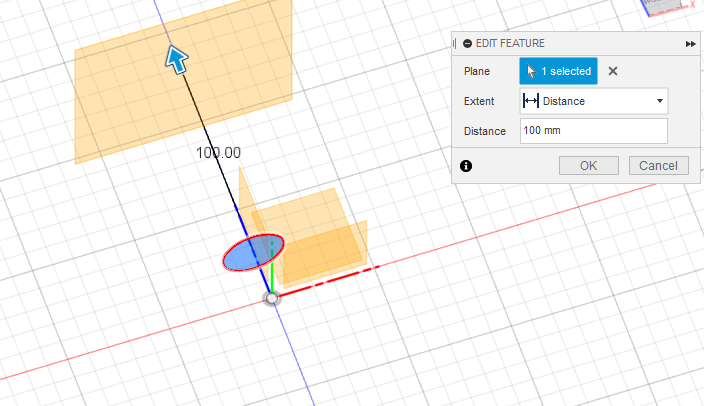
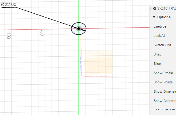
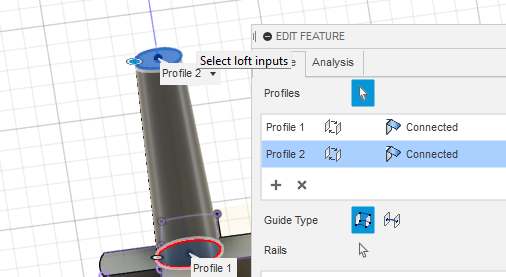
To start off, let's build a plane around 100 mm from the center circle that we just made in the previous step. After this, we will create a center circle on this plane of diameter 22 mm. Finally, create a loft to connect the circles and form handle.
Creating the Handle
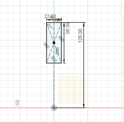
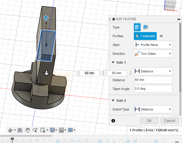
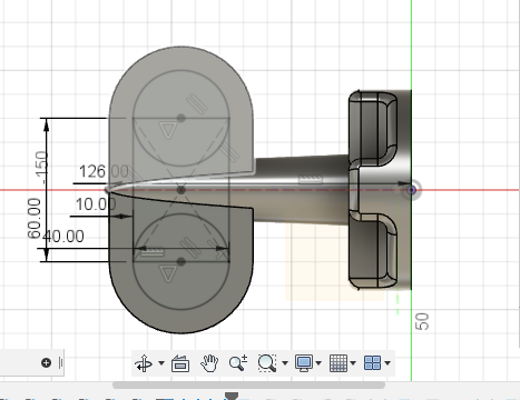
Create a sketch on the plane that cuts through the length of the loft. Create a sketch dimension of 126 mm from the origin, then create a center rectangle such that the width is 22 mm and the height is 60 mm where the bottom of the rectangle is 66 mm from the origin and top is 126 mm from the origin. Next, extrude the rectangle and select two sided extrusion. Extrude both sides by 60 mm!
Some Cleaning and Smoothing
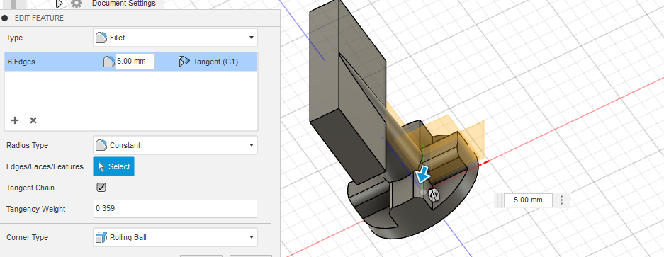
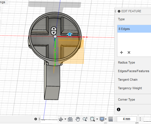
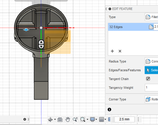
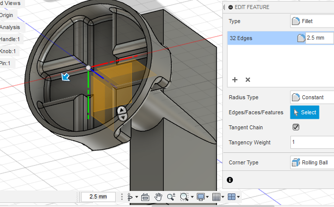
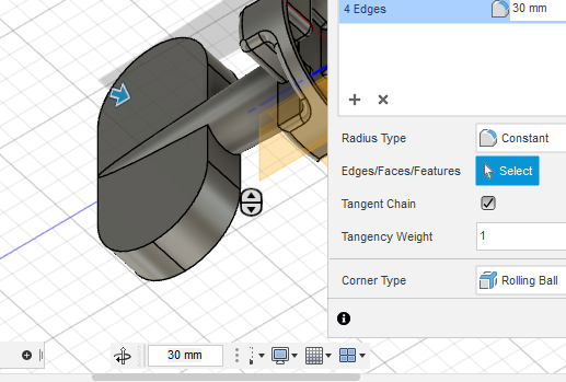
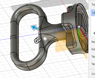
This step is going to involve the fillet feature. On your cross that is formed out of the extrusions, the linear edges on the top of the cross should all be selected for filleting. Then fillet by 5 mm. Next, at the bottom of the cross select all the bottom linear edges to be filleted by 4 mm. Next, select the edges which formed the arch at the top of the cross, and extrude these by 4 mm. Next, look at the underside of the base, and select all the edges of the top of the triangular pieces and fillet these by 4 mm. Then do the the rest of the edges on the triangular pieces by 2.5 mm (there should be a whopping 44 of these!). The last fillet for now is the edges of the handle and fillet these to 30 mm.
Handle Creation: Part 2
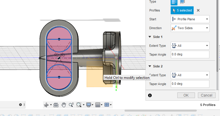
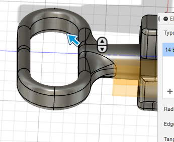
On the handle, create a sketch. Create a center rectangle formed from the center of the handle of dimensions 40 mm by 60 mm such that the 60 mm length is parallel to the linear parts of the handle. On each of the 40 mm lengths, create a circle of diameter 40 mm. Extrude the edges of the entire track curve (edges and half of each circle's circumference). Do a two sided cut and select under "Extent Type", "All". A picture is shown above.
Cleaning and Smoothing: Part 2
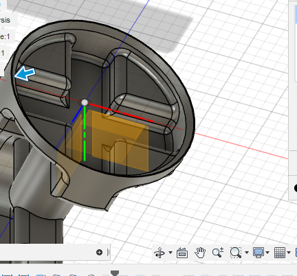
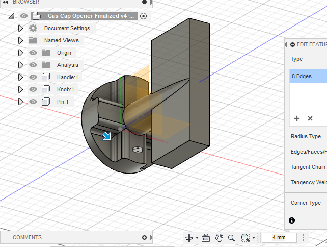
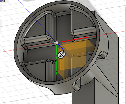
Select all the edges on the handle and fillet them by 5 mm. Then, on the bottom of the entire build (on the base) chamfer the inner edge of the base bottom ring by 2.5 mm (picture shown to clarify). An optional fillet is to fillet the handle and the stem together. You can choose different edges to fillet in order to vary how smooth you want the transition from handle to stem to be. Do a fillet of 20 mm.
Screws on Actual Handle
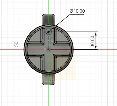
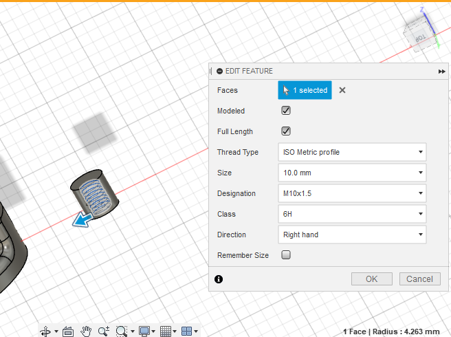
Create a sketch on the cross looking down at the handle. Create two circles 30 mm from origin (from each side) of diameter 10 mm. Extrude the circles by 10 mm. Then thread the two extrusions to using ISO Metric Profile thread type and designation M10x1.5, class 6g, and Right Hand direction.
Connection Hole
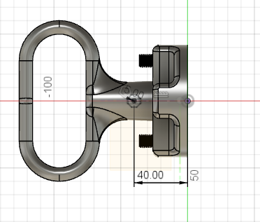
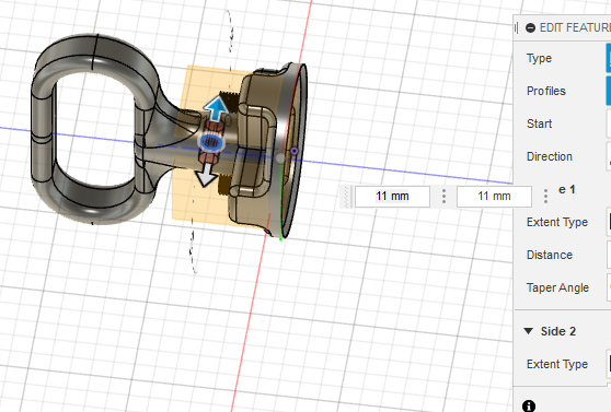
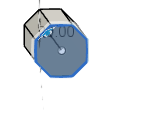
Create a sketch on the plane of the front view of the figure. Create a sketch dimension of 40 mm from the base of the figure, and create an octagon of radius 5 mm on the end of the 40 mm sketch dimension (on the handle). Then do a two sided extrusion on this octagon of 11 mm on both sides.
Splitting the Figure
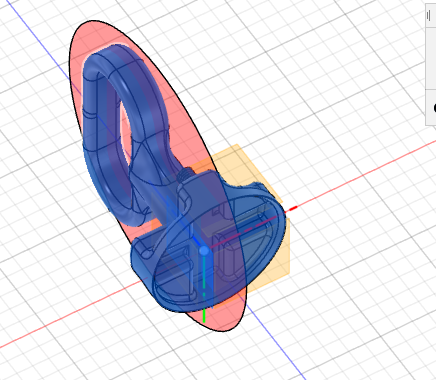
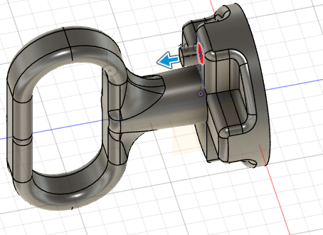
This is probably the easiest step yet (yay!). Simply use the split face command and split the figure so that the figure is cut in half in the plane that would cut the screws in half.
Creating the Actual Screws
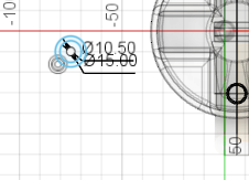
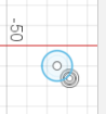
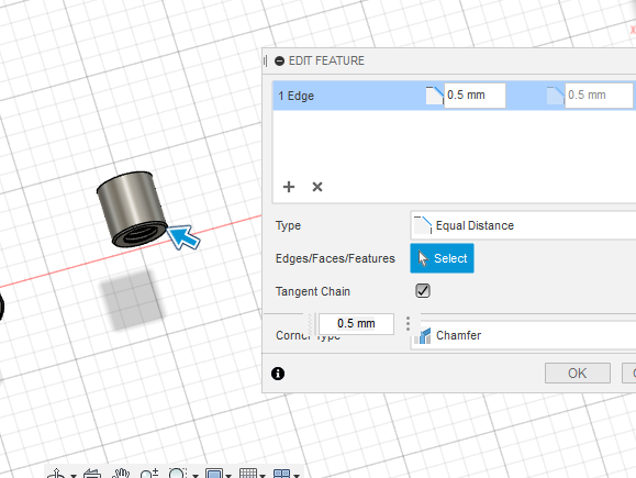
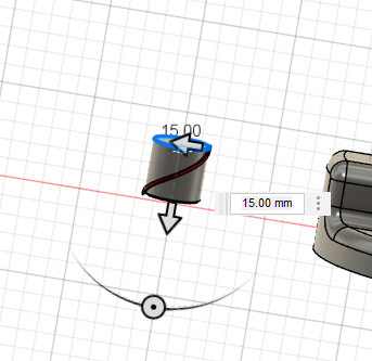
On the Knob Profile, create a new sketch. On this sketch create two concentric circles, one with diameter 10.5 mm the other with diameter 15 mm. Extrude this by 12.5 mm. Then create a sketch which has a 15 mm diameter circle on top of the extruded piece. Then extrude the new circle by 2.5 mm. Thread the inside of the screw piece using the same settings as used when creating screw on actual handle. Chamfer the edge of the screw outer edge (on bottom) by 0.5 mm. Then, preform a CoilPrimative on the top circle of the screw with a value of 15 mm (make sure operation type is cut). Finally, add a full distribution with quantity 15 C-pattern on the screw (for aesthetics).
Connection Piece
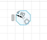
Under the Pin Component, create a new sketch of a octagon of radius 4.8 mm. Then extrude this sketch to 20 mm. Congrats! You have just finished designing the Assistive Handle!
Adjust Parameters As Needed
Go back to the Parameters menu and adjust the parameters as needed for your gas can size.
Delete a Face
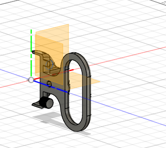
Click on delete face as you are going to need to print this print twice as most 3D printers aren't big enough for doing this whole design!
Export Your Fusion 360 File
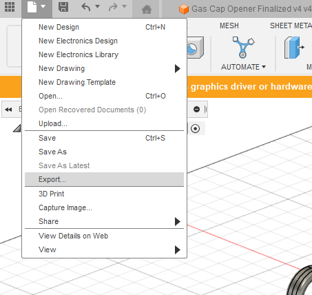
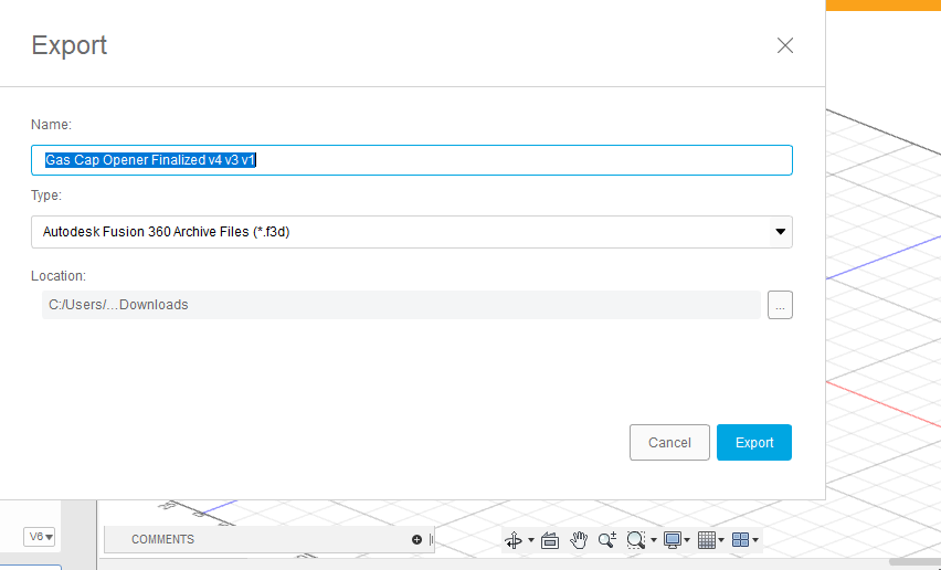
On the top left of the screen click File->Export->Export. This will save your Fusion file to your computer.
Import Into PrusaSlicer 2.5.0
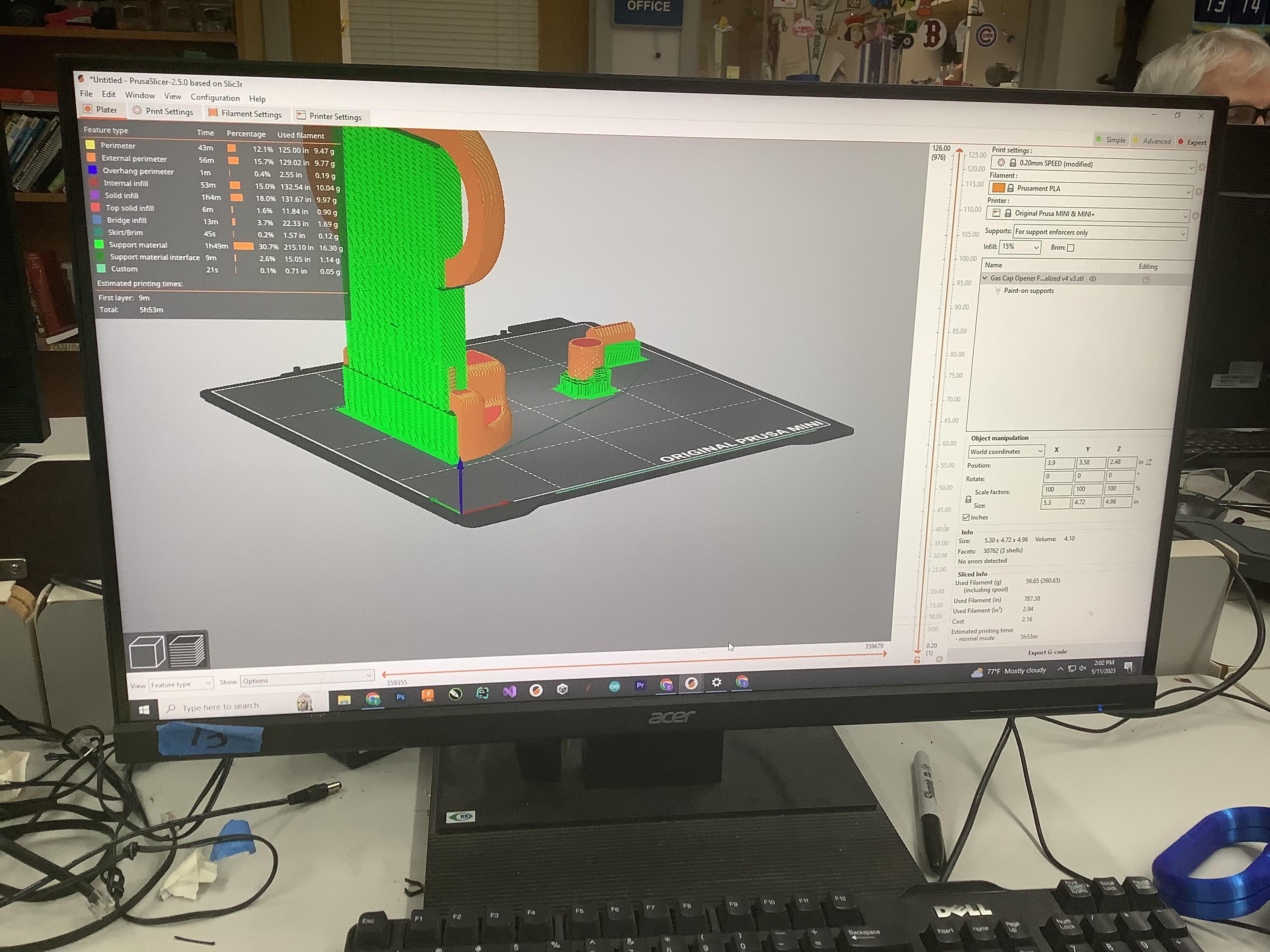
Import your design into the PrusaSlicer 2.5.0 software. Add and remove supports as necessary to minimize print time! Then click Export and export your G-Code!
Its Time to Print!
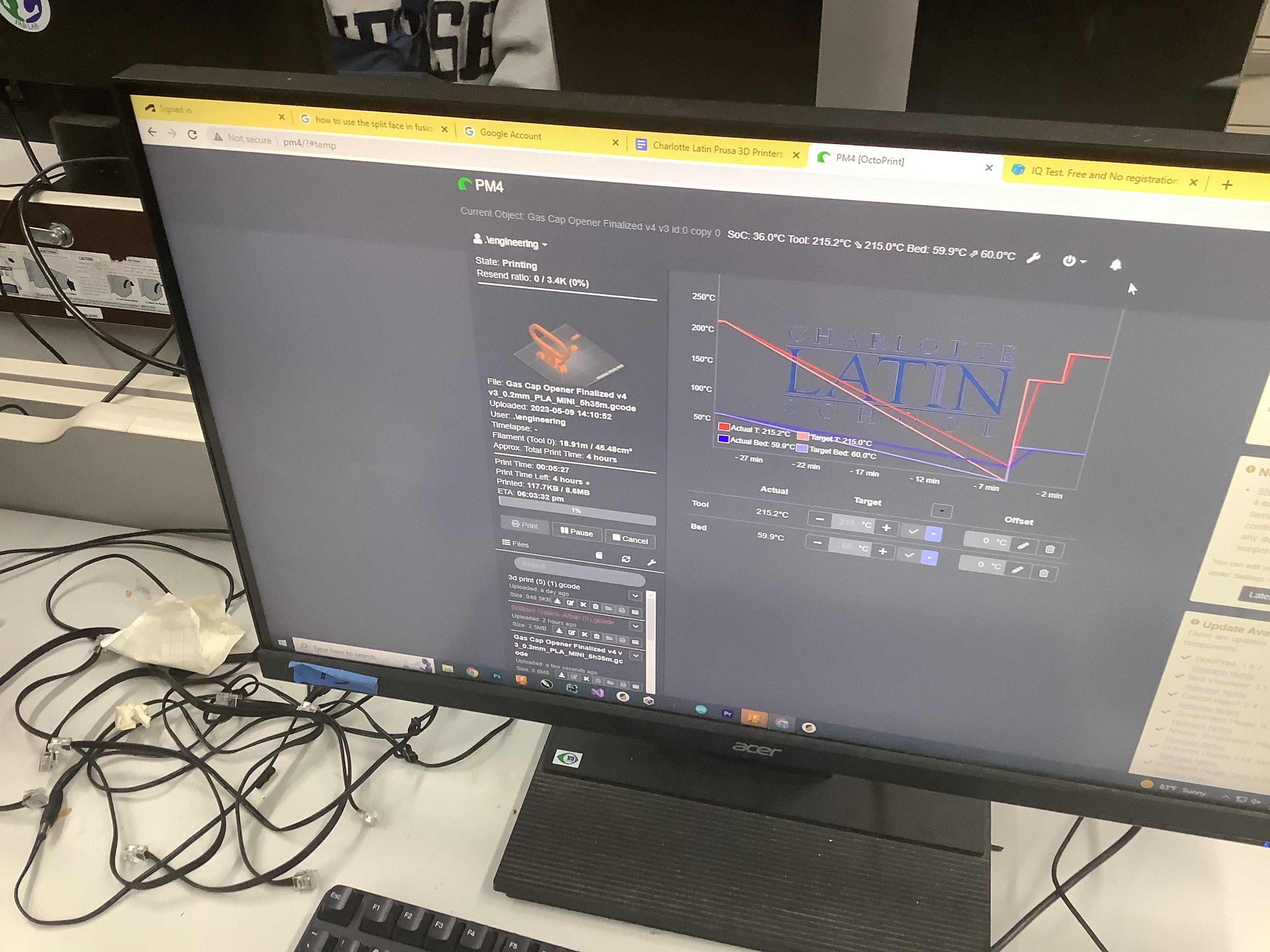
Import your Exported G-code into the PrusaSlicer printing service website (for your 3D Printer). Before you print make sure to wipe your print bed! Then simply click print build and watch as your masterpiece forms! Remember, you need to do this twice to get both halves of your design.
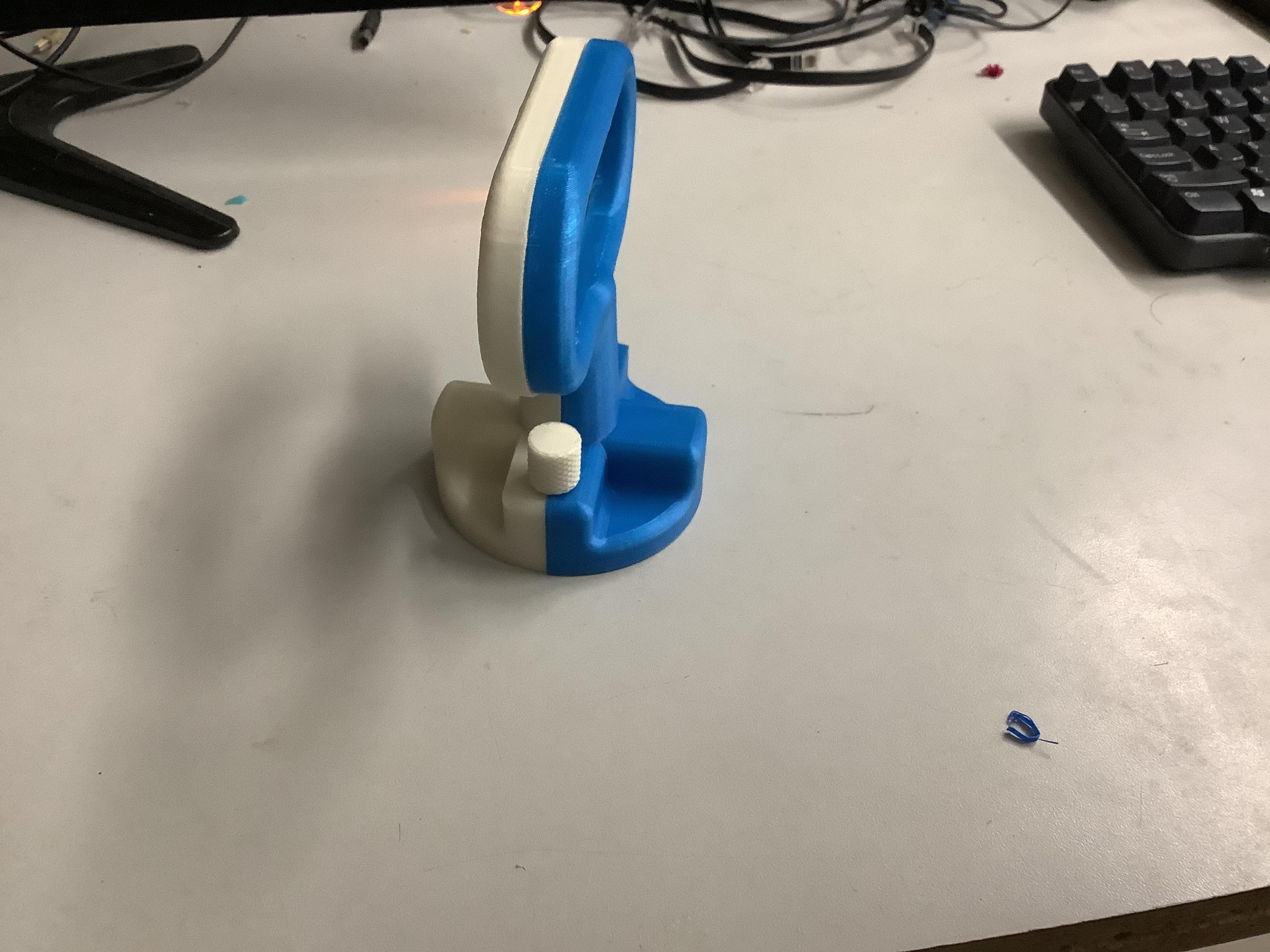
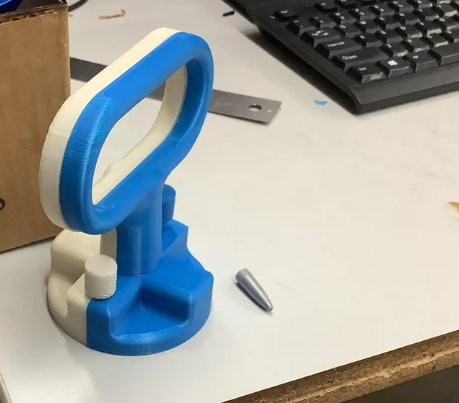
Connect Your Design

Once you have both of your design, use tweezers to get rid of supports. Then place your pin/connection piece in the slot of one of the halves and connect the two halves of the design. Then screw in your screws to get your finished product. Congrats on helping out people who are not as fortunate as me and you! Feel proud of yourself and give yourself a pat on the back!!!