How to Get Started With Arduino
by antoine57 in Circuits > Microcontrollers
3522 Views, 59 Favorites, 0 Comments
How to Get Started With Arduino
![IMG_5574[1].JPG](/proxy/?url=https://content.instructables.com/F0S/EOII/IZ6CAQZW/F0SEOIIIZ6CAQZW.jpg&filename=IMG_5574[1].JPG)
So you want to get started with Arduino huh? Well, you came to the right place. Today, i'm gonna show you how to get started with Arduino. Lets go!
What Is Arduino and His History.

Arduino is a computer and software community. They manufactures microcontroller boards and kits for building projects. The project is distributed as open-source hardware and sofware. This means permetting the manufacture of Arduino boards and software by anyone. The boards feature an USB to serial communication interface. The microcontrollers are programmed in a language called C and C++. Also, the Arduino Project provide and Integrated Develepment Environement (IDE) based on the Processing language project
The Arduino started in 2005 as a program for students at the Interaction Desing Institue in Ivrea, Italy. The goal was to provide a low-cost and easy way for novices and professionals to create devices that interact with their environment using sensors and actuators. The name Arduino comes from a bar in Ivrea, Italy, where the founders of the project used to meet. The bar was named after Arduino of Ivrea, who was the margrave of the March of Ivrea and King of Italy from 1002 to 1014.
The Arduino is open-source hardware. The designs are disributed under Creative Commons Attribution Share-Alike 2.5 license. An official Bill of Materials of Arduino boards has never been released by the Arduino staff. The developers have requested that the name Arduino be exclusive to the official product and not be used for derived works without permission. The Arduino Uno consist of an Atmega328P-20PU chip from Atmel.
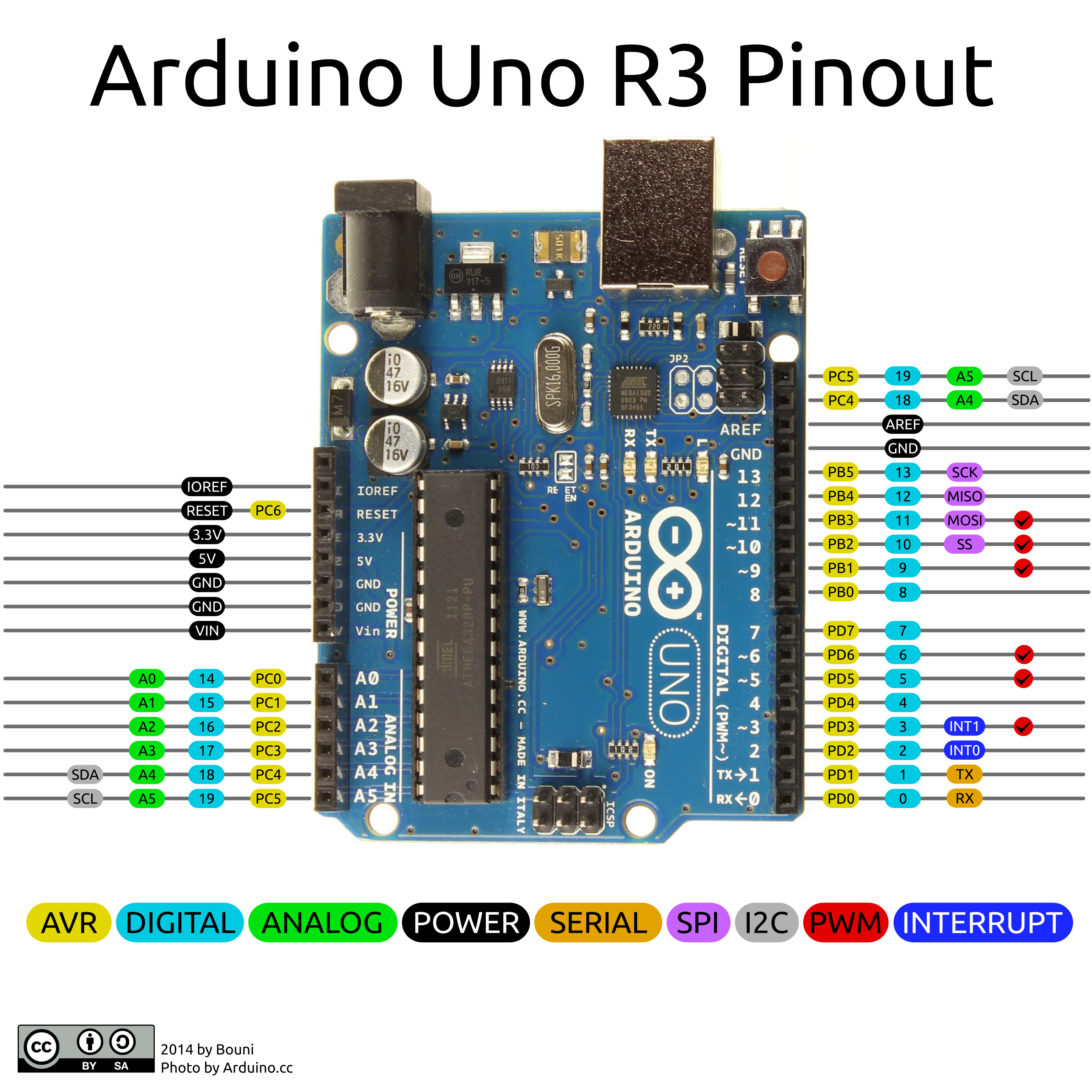
Arduino Uno PInout
Download the Arduino IDE
Follow these steps to download the Arduino IDE:
1. Go to https://www.arduino.cc/en/Main/Software
2. Click on Software
3. Click on either Windows, Mac or Linux.
4. You can donate if you want or just download.
5. When this is done, you will simply need to continue the steps to download it to your computer.
6. You are done!
Things You Will Need
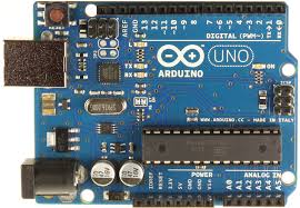
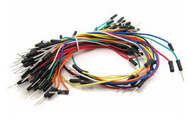
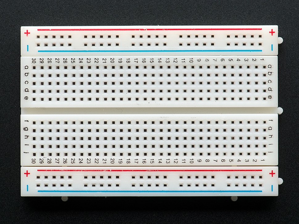
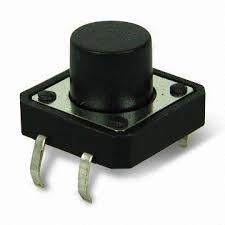
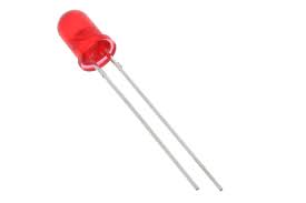
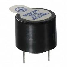
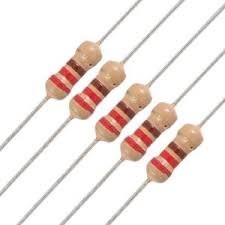
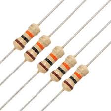
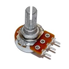
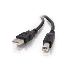
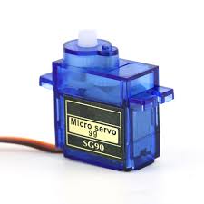
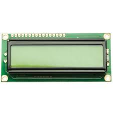
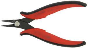
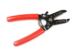

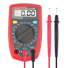
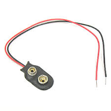
For this project, you will need:
1x Breadboard
1x Set of Jumper Wire
1x Arduino Uno ( I'm using a clone from China)
1x 5mm red LED
1x 220 Ohm resistor
1x 10k Ohm resistor
1x 5v Buzzer
1x 10k Potentiometer
1x Tactile Switch
1x 16x2 LCD display
1x Servo Motor
1x 9v battery and snap (optional)
1x USB type A to B cable
1x Multimeter (optional)
1x pair of pliers (optional)
1x diagonal cutters (optional)
1x Wire stripper (optional)
Make the Onboard LED Blink
![IMG_5589[1].JPG](/proxy/?url=https://content.instructables.com/FCK/LAW2/IZ6CB5X7/FCKLAW2IZ6CB5X7.jpg&filename=IMG_5589[1].JPG)
![IMG_5590[1].JPG](/proxy/?url=https://content.instructables.com/F2N/F30K/IZ6CB5YV/F2NF30KIZ6CB5YV.jpg&filename=IMG_5590[1].JPG)
![IMG_5745[1].JPG](/proxy/?url=https://content.instructables.com/FKC/TU4G/IZ6CB68A/FKCTU4GIZ6CB68A.jpg&filename=IMG_5745[1].JPG)
![IMG_5746[1].JPG](/proxy/?url=https://content.instructables.com/F4U/P77C/IZ6CB692/F4UP77CIZ6CB692.jpg&filename=IMG_5746[1].JPG)
![IMG_5751[1].JPG](/proxy/?url=https://content.instructables.com/F7I/UIIS/IZ6CB698/F7IUIISIZ6CB698.jpg&filename=IMG_5751[1].JPG)
![IMG_5752[1].JPG](/proxy/?url=https://content.instructables.com/FV5/294Y/IZ6CB69E/FV5294YIZ6CB69E.jpg&filename=IMG_5752[1].JPG)
![IMG_5753[1].JPG](/proxy/?url=https://content.instructables.com/F9E/V4DA/IZ6CB6B3/F9EV4DAIZ6CB6B3.jpg&filename=IMG_5753[1].JPG)
Are you ready for your first Arduino Project? Lets go!
Its gonna be easy if you follow these steps.
1. Plug the arduino to your computer using the USB cable.
2. You will see 2 LEDs light up, one meaning the board is ON and the other indicating that the bootloader is working.
3. Open your Arduino IDE.
4. Go to File -) Exemples -) Basic -) Blink.
5. Click on Upload, on the left of the screen.
6. It will say Done uploading is there is no problems.
7. If there is an error, please visit the arduino website, and they will be happy to assist you.
8. The LED will blink!
9. Bravo! You've just done your first Arduino Project!
What Is a Breadboard?
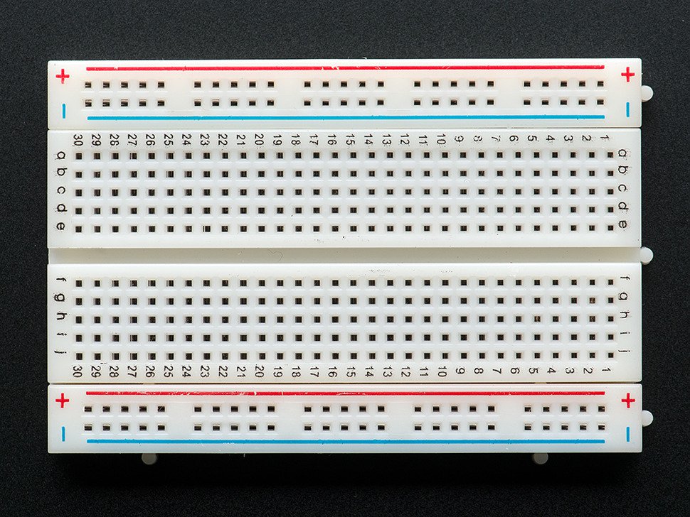
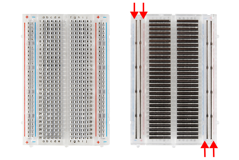
A breadboard is a cutting board to cut bread. Yeah, trust me!
Just kiddng! Its a prototyping platform, where you can plug components and remove them easily. Please refer to the photo to see how its made inside. There usualy is 2 bands on each sides indicating the power rails. Its made to easily connect all of the (-) and (+) together.
Make an LED Blink on a Breadboard
![IMG_5592[1].JPG](/proxy/?url=https://content.instructables.com/FS6/JVZ8/IZ6CBED5/FS6JVZ8IZ6CBED5.jpg&filename=IMG_5592[1].JPG)
![IMG_5593[1].JPG](/proxy/?url=https://content.instructables.com/FI1/M9TM/IZ6CBEGK/FI1M9TMIZ6CBEGK.jpg&filename=IMG_5593[1].JPG)
![IMG_5594[1].JPG](/proxy/?url=https://content.instructables.com/FNT/JQOB/IZ6CBEHZ/FNTJQOBIZ6CBEHZ.jpg&filename=IMG_5594[1].JPG)
![IMG_5595[1].JPG](/proxy/?url=https://content.instructables.com/FAJ/0H8D/IZ6CBEI3/FAJ0H8DIZ6CBEI3.jpg&filename=IMG_5595[1].JPG)
![IMG_5596[1].JPG](/proxy/?url=https://content.instructables.com/F75/OHS3/IZ6CBEJI/F75OHS3IZ6CBEJI.jpg&filename=IMG_5596[1].JPG)
![IMG_5597[1].JPG](/proxy/?url=https://content.instructables.com/FQ3/2USU/IZ6CBEKX/FQ32USUIZ6CBEKX.jpg&filename=IMG_5597[1].JPG)
![IMG_5598[1].JPG](/proxy/?url=https://content.instructables.com/FXH/SCST/IZ6CBEPS/FXHSCSTIZ6CBEPS.jpg&filename=IMG_5598[1].JPG)
![IMG_5599[1].JPG](/proxy/?url=https://content.instructables.com/F1C/CBCY/IZ6CBEQE/F1CCBCYIZ6CBEQE.jpg&filename=IMG_5599[1].JPG)
![IMG_5600[1].JPG](/proxy/?url=https://content.instructables.com/FU7/K32Y/IZ6CBES2/FU7K32YIZ6CBES2.jpg&filename=IMG_5600[1].JPG)
![IMG_5601[1].JPG](/proxy/?url=https://content.instructables.com/F16/I21L/IZ6CBETP/F16I21LIZ6CBETP.jpg&filename=IMG_5601[1].JPG)
![IMG_5602[1].JPG](/proxy/?url=https://content.instructables.com/FG2/CYG9/IZ6CBEV5/FG2CYG9IZ6CBEV5.jpg&filename=IMG_5602[1].JPG)
![IMG_5604[1].JPG](/proxy/?url=https://content.instructables.com/FSM/EAO0/IZ6CBEV6/FSMEAO0IZ6CBEV6.jpg&filename=IMG_5604[1].JPG)
![IMG_5606[1].JPG](/proxy/?url=https://content.instructables.com/FYS/KV4C/IZ6CBEWK/FYSKV4CIZ6CBEWK.jpg&filename=IMG_5606[1].JPG)
![IMG_5607[1].JPG](/proxy/?url=https://content.instructables.com/F2U/SMWU/IZ6CBEXZ/F2USMWUIZ6CBEXZ.jpg&filename=IMG_5607[1].JPG)
![IMG_5608[1].JPG](/proxy/?url=https://content.instructables.com/FS2/3167/IZ6CBEY2/FS23167IZ6CBEY2.jpg&filename=IMG_5608[1].JPG)
![IMG_5610[1].JPG](/proxy/?url=https://content.instructables.com/FCH/64W1/IZ6CBEY7/FCH64W1IZ6CBEY7.jpg&filename=IMG_5610[1].JPG)
You will need:
Breadboard x1
Arduino Uno x1
Jumper wires x1
220 ohms resistor x1
LED x1
USB cable x1
1. Take a red jumper and connect it to the red power rail. Connect the other end to the other red rail.
2. Do the same with the blue rail. Use a blue jumper instead of a red.
3. Take a red jumper, and connect it to 5V on the arduino. Connect the other end to one of the red power rails on the breadboard.
4. Connect a blue jumper to GND on arduino. Connect the other end to one of the blue power rails on the breadboard.
5. The LED as 2 leads. A short one and a long one. The long one indicate the positive (+) lead and the short one, the negative (-) lead. Its important to place the LED correctly because if you put in in the wrong way, it will not work.
6. Put the Long (+) lead at the left on the breadboard ( like shown in the photo)
7. Take the resistor and place one of his lead into the LED positive lead ( the left pin)
8. Take a red jumper, and connect it to the other resistor lead. Connect the other end to Arduino pin 13.
9. Take a blue jumper, and connect it to the blue power rail on the breadboard.
10. Connect your arduino via USB and watch the LED blink.
* Note that we did not uploded any code to the board because the blink sketch is already uploaded.
Make a Buzzer Play a Tone
![IMG_5612[1].JPG](/proxy/?url=https://content.instructables.com/F4N/18GA/IZ6CC0CF/F4N18GAIZ6CC0CF.jpg&filename=IMG_5612[1].JPG)
![IMG_5613[1].JPG](/proxy/?url=https://content.instructables.com/FV5/IQGB/IZ6CC0DQ/FV5IQGBIZ6CC0DQ.jpg&filename=IMG_5613[1].JPG)
![IMG_5614[1].JPG](/proxy/?url=https://content.instructables.com/F24/8FFO/IZ6CC0F5/F248FFOIZ6CC0F5.jpg&filename=IMG_5614[1].JPG)
![IMG_5615[1].JPG](/proxy/?url=https://content.instructables.com/FH8/LIJM/IZ6CC0GK/FH8LIJMIZ6CC0GK.jpg&filename=IMG_5615[1].JPG)
![IMG_5616[1].JPG](/proxy/?url=https://content.instructables.com/FOX/3HOU/IZ6CC0GP/FOX3HOUIZ6CC0GP.jpg&filename=IMG_5616[1].JPG)
The next thing we will do is make a buzzer play a tone.
We will basiclly remove the LED and resitor and replace it with a buzzer.
You will need:
Breadboard x1
Jumper Wires x1
Arduino Uno x1
5v buzzer x1
USB cable x1
1. Remove the LED and the 220 ohm resistor from the bredboard.
2. Place the buzzer negative (-) lead on the blue jumper wire.
3. Take the red jumper, and connect it to the other positive (+) lead on the buzzer.
4. Plug your USB cable into your Arduino
5. Your done!
* Note that we did not uploded any code to the board because the blink sketch is already uploaded.
Use a Tactile Switch
![IMG_5617[1].JPG](/proxy/?url=https://content.instructables.com/FWY/2NXY/IZ6CC14K/FWY2NXYIZ6CC14K.jpg&filename=IMG_5617[1].JPG)
![IMG_5618[1].JPG](/proxy/?url=https://content.instructables.com/FNA/SMDW/IZ6CC14L/FNASMDWIZ6CC14L.jpg&filename=IMG_5618[1].JPG)
![IMG_5619[1].JPG](/proxy/?url=https://content.instructables.com/FW3/6WRL/IZ6CC14M/FW36WRLIZ6CC14M.jpg&filename=IMG_5619[1].JPG)
![IMG_5620[1].JPG](/proxy/?url=https://content.instructables.com/FSB/W33A/IZ6CC14R/FSBW33AIZ6CC14R.jpg&filename=IMG_5620[1].JPG)
![IMG_5621[1].JPG](/proxy/?url=https://content.instructables.com/FDS/AOB1/IZ6CC14T/FDSAOB1IZ6CC14T.jpg&filename=IMG_5621[1].JPG)
![IMG_5622[1].JPG](/proxy/?url=https://content.instructables.com/FHG/4DFD/IZ6CC14U/FHG4DFDIZ6CC14U.jpg&filename=IMG_5622[1].JPG)
![IMG_5623[1].JPG](/proxy/?url=https://content.instructables.com/FHU/JTHZ/IZ6CC14X/FHUJTHZIZ6CC14X.jpg&filename=IMG_5623[1].JPG)
![IMG_5624[1].JPG](/proxy/?url=https://content.instructables.com/F0G/WP2K/IZ6CC16A/F0GWP2KIZ6CC16A.jpg&filename=IMG_5624[1].JPG)
![IMG_5625[1].JPG](/proxy/?url=https://content.instructables.com/F45/JIG6/IZ6CC17K/F45JIG6IZ6CC17K.jpg&filename=IMG_5625[1].JPG)
![IMG_5626[1].JPG](/proxy/?url=https://content.instructables.com/F18/POW6/IZ6CC18Y/F18POW6IZ6CC18Y.jpg&filename=IMG_5626[1].JPG)
![IMG_5627[1].JPG](/proxy/?url=https://content.instructables.com/FE7/N3CE/IZ6CC18Z/FE7N3CEIZ6CC18Z.jpg&filename=IMG_5627[1].JPG)
![IMG_5628[1].JPG](/proxy/?url=https://content.instructables.com/FI6/JNQH/IZ6CC1A9/FI6JNQHIZ6CC1A9.jpg&filename=IMG_5628[1].JPG)
For our next project, we are gonna use a tactile switch to turn on or off an LED.
You will need:
Arduino Uno x1
Breadboard x1
Jumper wires x1
Tactile switch x1
10k resistor x1
USB cable x1
1. Place the tactile switch into the breadboard as shown in the photo.
2. Place the 10k resistor on pin n.2 on the tactile switch ( the right most pin)
3. Take a red jumper and connect it to the other resistor lead.
4. Take the other end of the jumper and connect it to the blue negative rail of the breadboard.
5. Take an other jumper wire and connect it to the left pin of the tactile switch.
6. Connect the other end to the red positive rail of the breadboard.
7. Finally, connect a yellow wire from the top right pin of the tactile switch, to pin 2 of the arduino.
8. Connect your Arduino to you PC with the USB cable and open the IDE.
9. Go to File -) Exemple -) Digital -) Button and upload it to the arduino board.
How to use,
Press on the switch and watch the onboard LED light up!
Make a Servo Motor Move
![IMG_5629[1].JPG](/proxy/?url=https://content.instructables.com/FVZ/13JF/IZ6CC637/FVZ13JFIZ6CC637.jpg&filename=IMG_5629[1].JPG)
![IMG_5630[1].JPG](/proxy/?url=https://content.instructables.com/F71/5CDC/IZ6CC63G/F715CDCIZ6CC63G.jpg&filename=IMG_5630[1].JPG)
![IMG_5631[1].JPG](/proxy/?url=https://content.instructables.com/F74/1IRG/IZ6CC63R/F741IRGIZ6CC63R.jpg&filename=IMG_5631[1].JPG)
![IMG_5632[1].JPG](/proxy/?url=https://content.instructables.com/FTR/ETB0/IZ6CC63V/FTRETB0IZ6CC63V.jpg&filename=IMG_5632[1].JPG)
![IMG_5636[1].JPG](/proxy/?url=https://content.instructables.com/F98/FGX9/IZ6CC643/F98FGX9IZ6CC643.jpg&filename=IMG_5636[1].JPG)
![IMG_5637[1].JPG](/proxy/?url=https://content.instructables.com/F92/4KPG/IZ6CC647/F924KPGIZ6CC647.jpg&filename=IMG_5637[1].JPG)
![IMG_5641[1].JPG](/proxy/?url=https://content.instructables.com/FW8/AD7Q/IZ6CC64B/FW8AD7QIZ6CC64B.jpg&filename=IMG_5641[1].JPG)
![IMG_5643[1].JPG](/proxy/?url=https://content.instructables.com/FZK/RWXG/IZ6CC64I/FZKRWXGIZ6CC64I.jpg&filename=IMG_5643[1].JPG)
![IMG_5644[1].JPG](/proxy/?url=https://content.instructables.com/FC0/8CYY/IZ6CC64M/FC08CYYIZ6CC64M.jpg&filename=IMG_5644[1].JPG)
![IMG_5646[1].JPG](/proxy/?url=https://content.instructables.com/F2A/36UB/IZ6CC64S/F2A36UBIZ6CC64S.jpg&filename=IMG_5646[1].JPG)
![IMG_5647[1].JPG](/proxy/?url=https://content.instructables.com/FH9/69Y4/IZ6CC64Y/FH969Y4IZ6CC64Y.jpg&filename=IMG_5647[1].JPG)
![IMG_5648[1].JPG](/proxy/?url=https://content.instructables.com/FZW/5PO2/IZ6CC653/FZW5PO2IZ6CC653.jpg&filename=IMG_5648[1].JPG)
![IMG_5649[1].JPG](/proxy/?url=https://content.instructables.com/FGA/YGES/IZ6CC655/FGAYGESIZ6CC655.jpg&filename=IMG_5649[1].JPG)
Ok! Now its time to make a servo motor move!
You will need:
Servo Motor x1
Breadoard x1
Arduino Uno x1
Jumper Wires x1¸
USB cable x1
1. connect the red middle pin of the servo to 5v on the breadboard
2. Plug the brown servo wire to GND on the breadboard
3. Connect the yellow servo wire to pin 9 on the Arduino.
Adjust The servo horn
1. Place horn on the servo motor.
2.Turn it conter-clockwise until it stop.
3. Pull the horn out of the servo
4. Place it again in the middle.
4. PLug the USB cable into your arduino and in your computer.
5. Open the IDE and go to file -) Exemples-) Sevo -) Sweep
6. Upload the code into your Arduino
7. Your are done!
Final Project : Write Text on 16x2 LCD
![IMG_5700[1].JPG](/proxy/?url=https://content.instructables.com/FCT/BGE0/IZ6CCB0F/FCTBGE0IZ6CCB0F.jpg&filename=IMG_5700[1].JPG)
![IMG_5699[1].JPG](/proxy/?url=https://content.instructables.com/FHM/3MUF/IZ6CCAWF/FHM3MUFIZ6CCAWF.jpg&filename=IMG_5699[1].JPG)
![IMG_5698[1].JPG](/proxy/?url=https://content.instructables.com/F11/DSZH/IZ6CCAW3/F11DSZHIZ6CCAW3.jpg&filename=IMG_5698[1].JPG)
![IMG_5697[1].JPG](/proxy/?url=https://content.instructables.com/FX4/U767/IZ6CCAUN/FX4U767IZ6CCAUN.jpg&filename=IMG_5697[1].JPG)
![IMG_5696[1].JPG](/proxy/?url=https://content.instructables.com/FKN/1BMY/IZ6CCATE/FKN1BMYIZ6CCATE.jpg&filename=IMG_5696[1].JPG)
![IMG_5695[1].JPG](/proxy/?url=https://content.instructables.com/FHN/1WWD/IZ6CCAT4/FHN1WWDIZ6CCAT4.jpg&filename=IMG_5695[1].JPG)
![IMG_5694[1].JPG](/proxy/?url=https://content.instructables.com/F94/AN9U/IZ6CCAS1/F94AN9UIZ6CCAS1.jpg&filename=IMG_5694[1].JPG)
![IMG_5693[1].JPG](/proxy/?url=https://content.instructables.com/FPT/U3SX/IZ6CCAR7/FPTU3SXIZ6CCAR7.jpg&filename=IMG_5693[1].JPG)
![IMG_5692[1].JPG](/proxy/?url=https://content.instructables.com/F26/FFLH/IZ6CCAQY/F26FFLHIZ6CCAQY.jpg&filename=IMG_5692[1].JPG)
![IMG_5690[1].JPG](/proxy/?url=https://content.instructables.com/FUA/HP6N/IZ6CCAQQ/FUAHP6NIZ6CCAQQ.jpg&filename=IMG_5690[1].JPG)
![IMG_5689[1].JPG](/proxy/?url=https://content.instructables.com/FLQ/B9QB/IZ6CCAQI/FLQB9QBIZ6CCAQI.jpg&filename=IMG_5689[1].JPG)
![IMG_5688[1].JPG](/proxy/?url=https://content.instructables.com/F68/TW73/IZ6CCAPN/F68TW73IZ6CCAPN.jpg&filename=IMG_5688[1].JPG)
![IMG_5687[1].JPG](/proxy/?url=https://content.instructables.com/FOE/D18N/IZ6CCAOT/FOED18NIZ6CCAOT.jpg&filename=IMG_5687[1].JPG)
![IMG_5686[1].JPG](/proxy/?url=https://content.instructables.com/FLB/GA6V/IZ6CCAOL/FLBGA6VIZ6CCAOL.jpg&filename=IMG_5686[1].JPG)
![IMG_5685[1].JPG](/proxy/?url=https://content.instructables.com/FBF/GNJA/IZ6CCAOD/FBFGNJAIZ6CCAOD.jpg&filename=IMG_5685[1].JPG)
![IMG_5684[1].JPG](/proxy/?url=https://content.instructables.com/FS5/P6TP/IZ6CCANC/FS5P6TPIZ6CCANC.jpg&filename=IMG_5684[1].JPG)
![IMG_5682[1].JPG](/proxy/?url=https://content.instructables.com/FWT/LUFO/IZ6CCANA/FWTLUFOIZ6CCANA.jpg&filename=IMG_5682[1].JPG)
![IMG_5681[1].JPG](/proxy/?url=https://content.instructables.com/FZG/8RU8/IZ6CCAMD/FZG8RU8IZ6CCAMD.jpg&filename=IMG_5681[1].JPG)
![IMG_5680[1].JPG](/proxy/?url=https://content.instructables.com/FIQ/8ETW/IZ6CCAJY/FIQ8ETWIZ6CCAJY.jpg&filename=IMG_5680[1].JPG)
![IMG_5679[1].JPG](/proxy/?url=https://content.instructables.com/FVA/RXLR/IZ6CCAJB/FVARXLRIZ6CCAJB.jpg&filename=IMG_5679[1].JPG)
![IMG_5678[1].JPG](/proxy/?url=https://content.instructables.com/FT9/ESAX/IZ6CCAHM/FT9ESAXIZ6CCAHM.jpg&filename=IMG_5678[1].JPG)
![IMG_5677[1].JPG](/proxy/?url=https://content.instructables.com/FFC/MCMB/IZ6CCAHL/FFCMCMBIZ6CCAHL.jpg&filename=IMG_5677[1].JPG)
![IMG_5676[1].JPG](/proxy/?url=https://content.instructables.com/F75/1RYM/IZ6CCAGR/F751RYMIZ6CCAGR.jpg&filename=IMG_5676[1].JPG)
![IMG_5675[1].JPG](/proxy/?url=https://content.instructables.com/FNZ/C7V3/IZ6CCAFO/FNZC7V3IZ6CCAFO.jpg&filename=IMG_5675[1].JPG)
![IMG_5674[1].JPG](/proxy/?url=https://content.instructables.com/FAM/6ON0/IZ6CCAEQ/FAM6ON0IZ6CCAEQ.jpg&filename=IMG_5674[1].JPG)
![IMG_5673[1].JPG](/proxy/?url=https://content.instructables.com/FQO/A2NF/IZ6CCADW/FQOA2NFIZ6CCADW.jpg&filename=IMG_5673[1].JPG)
![IMG_5672[1].JPG](/proxy/?url=https://content.instructables.com/F7Q/CO4B/IZ6CCAD2/F7QCO4BIZ6CCAD2.jpg&filename=IMG_5672[1].JPG)
![IMG_5671[1].JPG](/proxy/?url=https://content.instructables.com/FQ2/VXUV/IZ6CCACD/FQ2VXUVIZ6CCACD.jpg&filename=IMG_5671[1].JPG)
![IMG_5670[1].JPG](/proxy/?url=https://content.instructables.com/FWD/H4B2/IZ6CCACB/FWDH4B2IZ6CCACB.jpg&filename=IMG_5670[1].JPG)
![IMG_5668[1].JPG](/proxy/?url=https://content.instructables.com/FO4/5QDQ/IZ6CCAAK/FO45QDQIZ6CCAAK.jpg&filename=IMG_5668[1].JPG)
![IMG_5666[1].JPG](/proxy/?url=https://content.instructables.com/FGI/OCM1/IZ6CCA8E/FGIOCM1IZ6CCA8E.jpg&filename=IMG_5666[1].JPG)
![IMG_5665[1].JPG](/proxy/?url=https://content.instructables.com/FXG/ISPD/IZ6CCA78/FXGISPDIZ6CCA78.jpg&filename=IMG_5665[1].JPG)
![IMG_5664[1].JPG](/proxy/?url=https://content.instructables.com/FL6/TX7H/IZ6CCA6T/FL6TX7HIZ6CCA6T.jpg&filename=IMG_5664[1].JPG)
![IMG_5663[1].JPG](/proxy/?url=https://content.instructables.com/FF8/RIO9/IZ6CCA4O/FF8RIO9IZ6CCA4O.jpg&filename=IMG_5663[1].JPG)
![IMG_5662[1].JPG](/proxy/?url=https://content.instructables.com/F9J/WSJ2/IZ6CCA32/F9JWSJ2IZ6CCA32.jpg&filename=IMG_5662[1].JPG)
![IMG_5661[1].JPG](/proxy/?url=https://content.instructables.com/F25/9P6D/IZ6CCA2N/F259P6DIZ6CCA2N.jpg&filename=IMG_5661[1].JPG)
![IMG_5660[1].JPG](/proxy/?url=https://content.instructables.com/FPC/1B4K/IZ6CCA2M/FPC1B4KIZ6CCA2M.jpg&filename=IMG_5660[1].JPG)
![IMG_5659[1].JPG](/proxy/?url=https://content.instructables.com/FE4/U80R/IZ6CCA2L/FE4U80RIZ6CCA2L.jpg&filename=IMG_5659[1].JPG)
![IMG_5658[1].JPG](/proxy/?url=https://content.instructables.com/FAY/UTHM/IZ6CCA2K/FAYUTHMIZ6CCA2K.jpg&filename=IMG_5658[1].JPG)
![IMG_5657[1].JPG](/proxy/?url=https://content.instructables.com/FHC/VIKC/IZ6CCA2E/FHCVIKCIZ6CCA2E.jpg&filename=IMG_5657[1].JPG)
![IMG_5656[1].JPG](/proxy/?url=https://content.instructables.com/F6P/A4IF/IZ6CCA1O/F6PA4IFIZ6CCA1O.jpg&filename=IMG_5656[1].JPG)
![IMG_5655[1].JPG](/proxy/?url=https://content.instructables.com/F8T/1SDA/IZ6CCA1A/F8T1SDAIZ6CCA1A.jpg&filename=IMG_5655[1].JPG)
![IMG_5654[1].JPG](/proxy/?url=https://content.instructables.com/FRZ/BJF5/IZ6CCA0G/FRZBJF5IZ6CCA0G.jpg&filename=IMG_5654[1].JPG)
![IMG_5653[1].JPG](/proxy/?url=https://content.instructables.com/FPD/SJY1/IZ6CC9ZW/FPDSJY1IZ6CC9ZW.jpg&filename=IMG_5653[1].JPG)
![IMG_5652[1].JPG](/proxy/?url=https://content.instructables.com/FJV/NC8X/IZ6CC9ZR/FJVNC8XIZ6CC9ZR.jpg&filename=IMG_5652[1].JPG)
![IMG_5651[1].JPG](/proxy/?url=https://content.instructables.com/FDR/WROX/IZ6CC9YQ/FDRWROXIZ6CC9YQ.jpg&filename=IMG_5651[1].JPG)
![IMG_5650[1].JPG](/proxy/?url=https://content.instructables.com/FWJ/RE8K/IZ6CC9XG/FWJRE8KIZ6CC9XG.jpg&filename=IMG_5650[1].JPG)
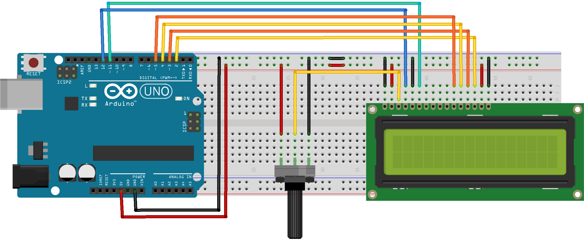
Are you ready for your final project? You've made it! Almost...
We are gonna write text on a simple 16x LCD screen.
You will need:
Arduino Uno x1
Breadboard x1
USB cable x1
10k Potentiometer x1
16x2 LCD x1
Jumper Wires x1
* The photos order is in the wrong way around. Please start with the very last photo ( step 1).
1. Because now you are an expert at electronic, im not gonna explain you step by step every steps, but i have pictures and a bredboard layout.
2. Connect your arduino with the USB cable to your computer.
3. Open the IDE and go to File -) Exemples -) LiquidCrystal -) HelloWorld.
4 Click the upload button.
5. Your done! Finally!
Resistor Hack
![IMG_5701[1].JPG](/proxy/?url=https://content.instructables.com/F32/UDQN/IZ6CCKOW/F32UDQNIZ6CCKOW.jpg&filename=IMG_5701[1].JPG)
![IMG_5703[1].JPG](/proxy/?url=https://content.instructables.com/FAD/FVAK/IZ6CCKP2/FADFVAKIZ6CCKP2.jpg&filename=IMG_5703[1].JPG)
![IMG_5704[1].JPG](/proxy/?url=https://content.instructables.com/FK3/P52V/IZ6CCKP6/FK3P52VIZ6CCKP6.jpg&filename=IMG_5704[1].JPG)
![IMG_5705[1].JPG](/proxy/?url=https://content.instructables.com/FM0/F32R/IZ6CCKPR/FM0F32RIZ6CCKPR.jpg&filename=IMG_5705[1].JPG)
![IMG_5706[1].JPG](/proxy/?url=https://content.instructables.com/FL1/V9MR/IZ6CCKPS/FL1V9MRIZ6CCKPS.jpg&filename=IMG_5706[1].JPG)
![IMG_5709[1].JPG](/proxy/?url=https://content.instructables.com/FQL/CAK2/IZ6CCKPV/FQLCAK2IZ6CCKPV.jpg&filename=IMG_5709[1].JPG)
Here is a simple hack when you are using resistors on a bredboard!