How to Flash or Program ESP8266 AT Firmware by Using ESP8266 Flasher and Programmer, IOT Wifi Module
by mybotic in Circuits > Electronics
46185 Views, 14 Favorites, 0 Comments
How to Flash or Program ESP8266 AT Firmware by Using ESP8266 Flasher and Programmer, IOT Wifi Module
Description:
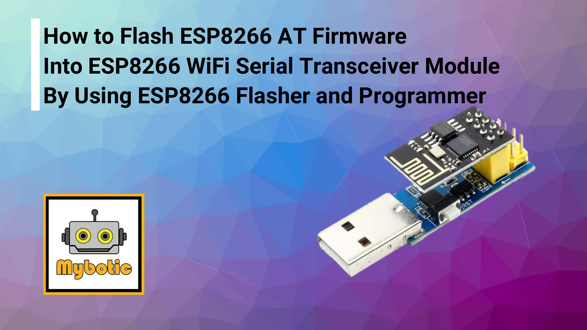
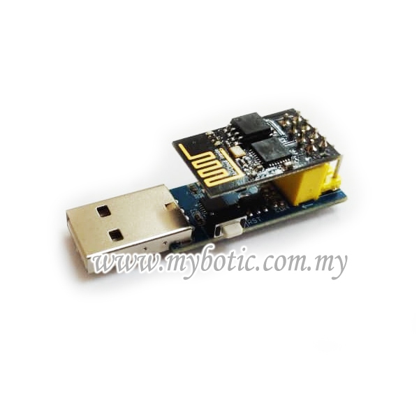
This Module is an USB adapter /programmer for ESP8266 modules of type ESP-01 or ESP-01S. It is conveniently fitted with a 2x4P 2.54mm female header to plug the ESP01. Also it breaks out all the pins of the ESP-01 via a 2x4P 2.54mm male header, so it is very convenient for user to debug the ESP8266.
The module is based on the USB-UART CP2104 which is compatible with all platforms. Onboard with the ESP8266 automatic download circuit. It is very convenient for users to download ESP-01/01S program, upgrade firmware, serial debugging and so on. It supports lots of software such as Arduino IDE, ESP8266 Flasher and Lexin FLASH_DOWNLOAD_TOOLS .
Specification:
- USB Type A interface.
- One 2x4P 2.54mm female header
- One 2x4P 2.54mm male header
- Operating Volatge: 3.3V
List of Material
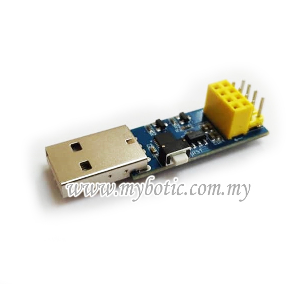
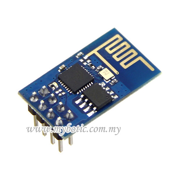

The attached photo shows the component needed In this tutorial:
- ESP8266 Flasher and Programmer
- ESP8266 Wifi Serial Transceiver Module
- Jumper wire.
Hardware Installation
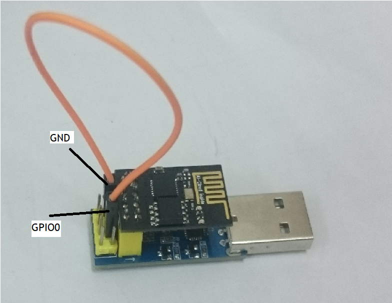
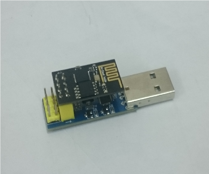
The photo above shows the connection between ESP8266 Flasher and Programmer and ESP8266 Wifi Serial Transceiver Module by using jumper wire.
Download File
Download Driver for ESP8266 Flasher and Programmer
Download firmware inside the ESP8266 Flash Tool folder.
And Install the driver.
Downloads
Firmware Installation
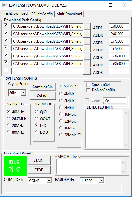
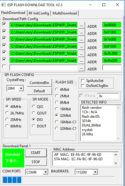
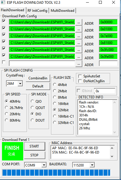
Window ( AT Firmware)
- After Download Firmware Flasher file. Extract it. Enter the folder, go to install_firmware > window.
- Open ESP_DOWNLOAD_TOOL_V2.4.exe.
-
Choose the COM port ESP8266 Flasher and Programmer + ESP8266 Wifi Serial Transceiver module connecting to. Set the BAUDRATE to 115200.
-
Make sure ESP8266 Wifi Serial Transceiver module is in FLASH mode (Refer Step 2 first photo for hardware configuration)
-
Click START to install the firmware.
- bin\boot_v1.2.bin 0x00000
- bin\user1.4096.new.4.bin 0x01000
- bin\blank.bin 0x7e000
- bin\user2.4096.new.4.bin 0x81000
- bin\esp_init_data_default.bin 0x3fc000
- bin\blank.bin 0x3fe000
AT Command in Arduino
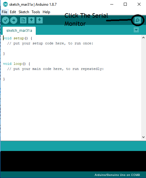
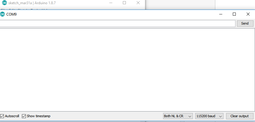
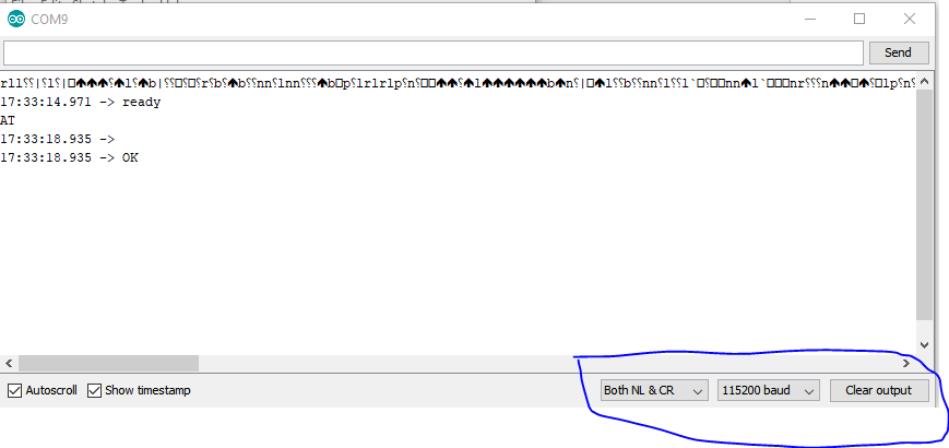
- Disconnect jumper wire from ESP8266 Flasher and Programmer (Refer step 2 second photo)
- Open your Arduino then click serial monitor.
- Press button Reset for make sure esp8266 is connected at serial monitor.
- Please follow the correct serial monitor configuration (Refer the photo above)
- Then write AT and send it, it will reply ok
- For more detail about AT Command, click this link for more information about AT Command
To change baudrate using AT Command:
AT+ UART_DEF=19200,8,1,0,0
For example 9600 baudrate / 8 data bits / 1 stop bits and none parity and flow control AT+UART_DEF=9600,8,1,0,0
the command AT+CIOBAUD=9600 it would change the baudrate temporarily
Let's Get Start !
