How to Design a Ported Subwoofer Box
by erbarnhi in Workshop > Cars
17272 Views, 11 Favorites, 0 Comments
How to Design a Ported Subwoofer Box
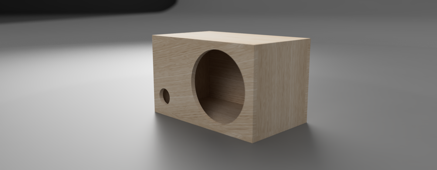
Stock audio systems can really lack in lower range bass and adding a custom subwoofer can really help in bringing those low notes to life. While there are tons of prefabricated boxes on the market, building a custom box for your subwoofer is a great way to make sure your subwoofer is performing at its best.
This step by step guide will help you learn how to design a ported subwoofer box, as well as learning how to use the basic functions of WinISD. This tutorial is for anyone looking to design a custom ported subwoofer box. This guide is intended for designing a ported box, since sealed boxes are much easier to design and build. However, the basic steps for a sealed box will be included.
Supplies
The only material you need for this project is a computer, and the free program from Linearteam in Finland, WinISD. Use the link below, and click on download latest version, run the installer, and follow the instructions to install the program.
WinISD - download link http://www.linearteam.org/
OPTIONAL - Solidworks, Fusion 360, or other similar 3d modeling program
STELs
Core Disciplinary Standards - Design in Technology and Engineering Education
This tutorial relates to the one of the key ideas of this standard, that making is an inherent part of technology and engineering design. The skills used in this tutorial such as measuring, sketching, and CAD are integral parts of this core standard.
Practices - Making and Doing
In these terms, making refers to the act of creating something, and doing refers to the hands-on processes associated with designing and building. This tutorial does not cover the physical building of the box, but the creation of the design and plans to be used to build the box later. The skills listed above are also key pieces to this practice.
Context - Computation, Automation, AI, and Robotics
This tutorial relates to the computation aspect of this context, using the program WinISD. Using and interpreting data is a key component of this context, and we do this in the tutorial with the data given from WinISD.
Rough Measuring
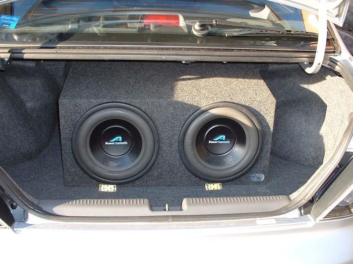
The very first step in building a custom sub box is measuring the area you have available. If planning to install into a car or SUV, the best place for the sub will be in the trunk or rear cargo area. If installing in a truck, under or behind the rear most seats will be the best location. You should measure the area where the box would roughly sit, and these measurements don’t have to be perfect, this is just to get an idea of how much space you have to work with.
Finding the Ideal Airspace
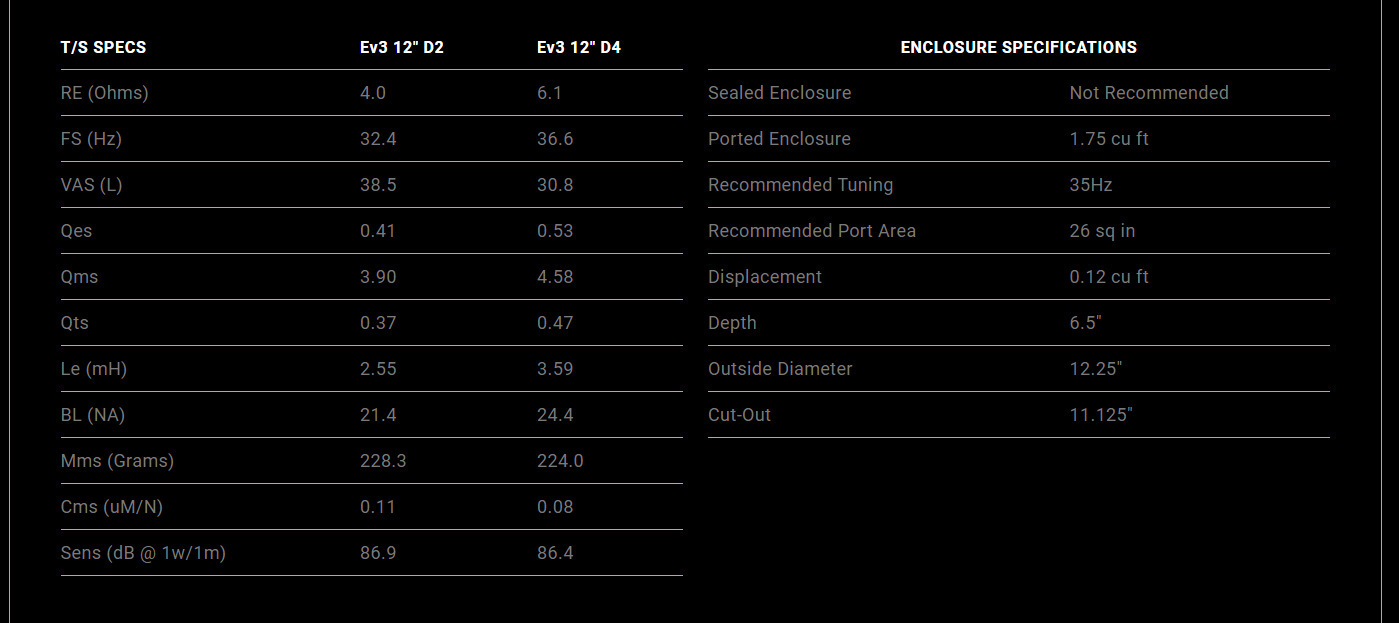
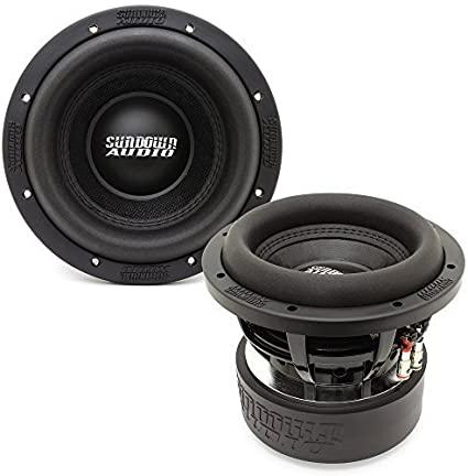
Each subwoofer has a recommended size box that it performs best in, and this differs if mounting in a sealed or ported box. For this guide, I chose to work with a Sundown Audio Ev3 10’, and to find what size box it would work best in, I checked the specs of the speaker, found on the Sundown website. Most subwoofer manufacturers have the specs for their speakers right on their websites, but some could be in the manuals. You must have the specs of your speaker for future steps. For the Ev3 10”, the recommended air space for a ported enclosure is 1.75 cubic feet. Also, the manufacturer states that this subwoofer is not recommended for a sealed enclosure. For your own project, you will only need the recommended airspace for which type of enclosure you plan to build.
After you find out your recommended airspace, compare it to the rough measurements you got earlier. You might want to convert the imaginary box’s measurements into cubic feet for a better comparison. The simple formula for finding this volume is multiplying the length, width, and height together. For example, if your rough measurements are a width of 2 feet, a height of 2 feet, and a length of 1.5 feet, you would have a volume of 6 cubic feet. If we use this for our Ev3 sub, we have more than enough space.
Setting Up WinISD
The size and shape of the ports can have a huge effect on how your subwoofer sounds. To get the most out of your sub, you can use a program called WinISD, a free program that helps you calculate port size, area, box tuning, among other things. While this may sound daunting, it's easier than you think.
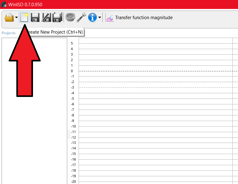
When you first open the software, you will need to create a new project. Do this by clicking on the 2nd button at the top.
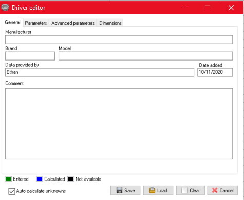
When starting a new project, a window will appear and prompt you to select a driver (subwoofer). WinISD has lots of subs already loaded in, but for this guide, I’ll be showing you how to enter in a new driver, so that you can follow along with any sub. For this, select the Add New option, and another window will appear. Go ahead and fill out the General page with some info about your sub, and then click over to the parameters tab at the top.
Entering Parameters
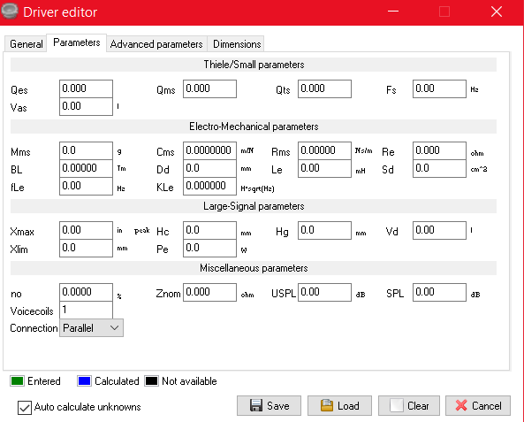
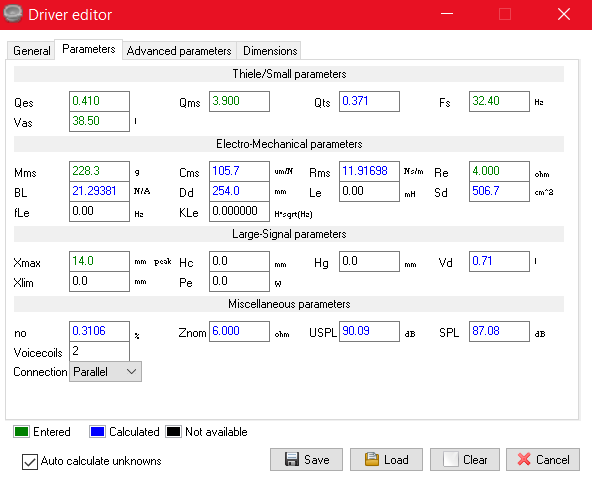
All these parameters are what makes your sub perform differently than others and allows us to calculate what the box should be like. Go back to your spec sheet for your subwoofer and start entering in the values. A tip for when entering in all these values is to utilize the tab key when moving to the next parameter. WinISD can auto calculate some of these and will help you save some time. If you find that some of your values are in a different unit than what you see in WinISD, clicking on the unit will cycle through the available options. It’s okay if you don’t have every box filled out. When you are finished on the parameters tab, click on save, and save your driver info.
Optimizing Your Box
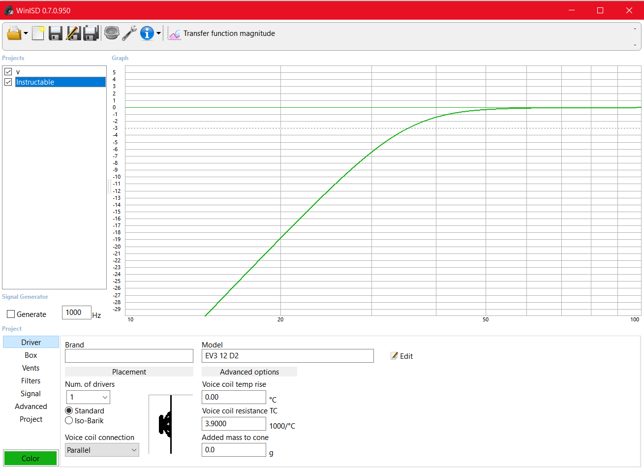
After you save your driver, click on the create new project button, find, and select your subwoofer. After the window loads, the first option to change is the number of drivers. Change this if you are using more than one subwoofer. The placement setting can be left at normal, and then click next. This next window allows you to choose what type of box to use for the calculations. For this example, I’ll be choosing a vented box, but other options including closed (sealed) boxes are available. The next window can be left at the default setting, after clicking next you will then name you project.
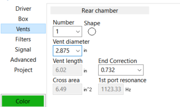
Click on the box tab in the lower left corner, and in the volume box, enter in the recommended airspace that we got earlier. In the box below volume we have tuning frequency. For my sub, a recommended tuning frequency was given at 35 Hz. If your sub doesn’t provide this, a bassline value from 32-40 Hz would be a good starting point. Next, click on the vents tab in the lower left corner. Many different port configurations are possible, and I encourage you to play around in this software and see the different results, but for this example, we will be using one circular port. You can buy cylindrical ports online, or you could use a piece of PVC pipe cut to length. Referring to my subwoofer spec sheet, I see that the recommended port area given is 26 square inches, so I should shoot for this value. To find the port area, multiply the Cross area and the Vent length given after plugging in a vent diameter. In my example, I used a vent diameter of 2.875 inches, and my port area came to 39 square inches, which is larger than I need. This is not a big deal now, since the given values change depending on the volume given and the tuning frequency.
After plugging in all these values, take a look at the graph shown. On the y-axis are decibels, and on the x-axis are Hertz. In a nutshell, the graph shows how the speaker will perform at different Hz (hertz), and you can click along the graph to get a more precise idea, shown by the data in the top right corner. The higher the Hz, the higher the note being played, and the higher the dB (decibels), the louder the speaker will be. Since we are building a box for a subwoofer, we aren’t really worried about the higher Hz (70+) levels. While this isn’t an accurate guide to exactly how loud your sub will be, it is a useful tool to compare how certain Hz will sound relative to others. Play around with the volume, and tuning frequency to see how the chart changes.
Designing the Box
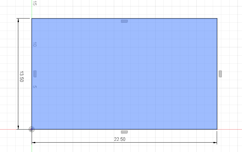
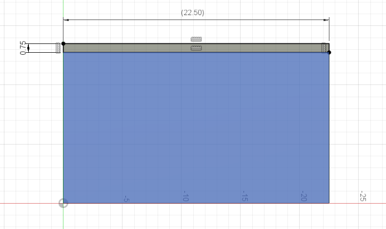
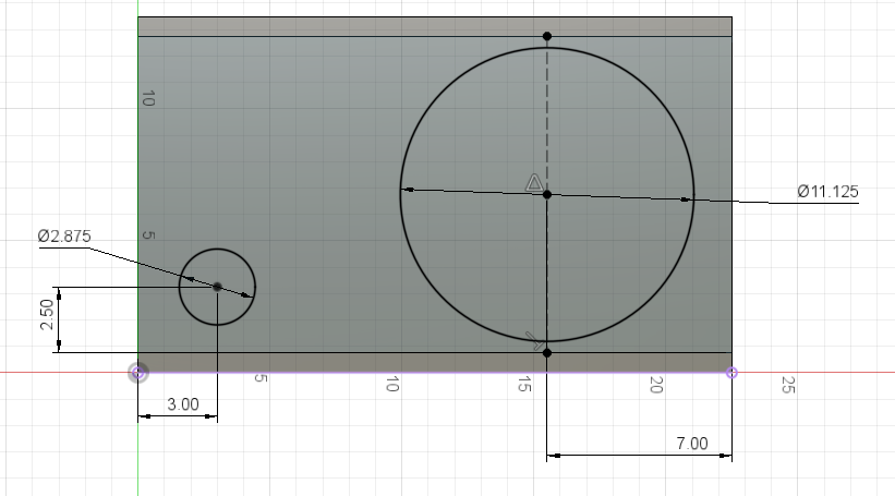
For my example I chose to use the 3d modeling program Fusion 360, but this can be done by hand sketching, or skipped completely if you choose to make the box just based on the numbers. Determining the dimensions of the box will vary for each application and requires some trial and error. For my box, I chose the dimensions of 13.5 in x 13.5 in x 22.5 in, giving me my desired air space of 1.75 cubic feet. When deciding on your dimensions, remember that the volume from WinISD or given from the manufacturer is the interior volume of the box, so this does not account for the thickness of the material. Most sub boxes are constructed with 3/4-inch MDF (medium density fiberboard) and I will be using this as my material.
When designing my sub box, I chose for the sides to be sandwiched by the top and bottom, which will affect the sizes of the pieces to be cut out. I started with the base, making a rectangle that is 22.5 inches by 13.5 inches, as to account for the thickness of the MDF. I then extruded this sketch by .75 inches to make the base for my box. Then I created another sketch for the back of my box and extruded it 12 inches. I repeated this process for the other 3 sides. Then I constructed the top, which was the same as the bottom. Next is to cut out the holes for the speaker and the port. Looking at the sub spec sheet, I can see that the cutout size for my speaker is 11.125 inches, so I’ll make that cut out of the front of the box, as well as the 2.875 inch hole for my port. You can place the holes wherever you like but placing the sub in the middle is recommended. After cutting out these holes my 3d model was done. You can add other features such as holes for wire terminals, but these can be placed after construction.
The process of sketching out or modeling your sub box isn’t essential, but it allows you to see how your box will look, how the box will be constructed, and can help avoid any errors.
(OPTIONAL) Construction Drawings From 3d Model
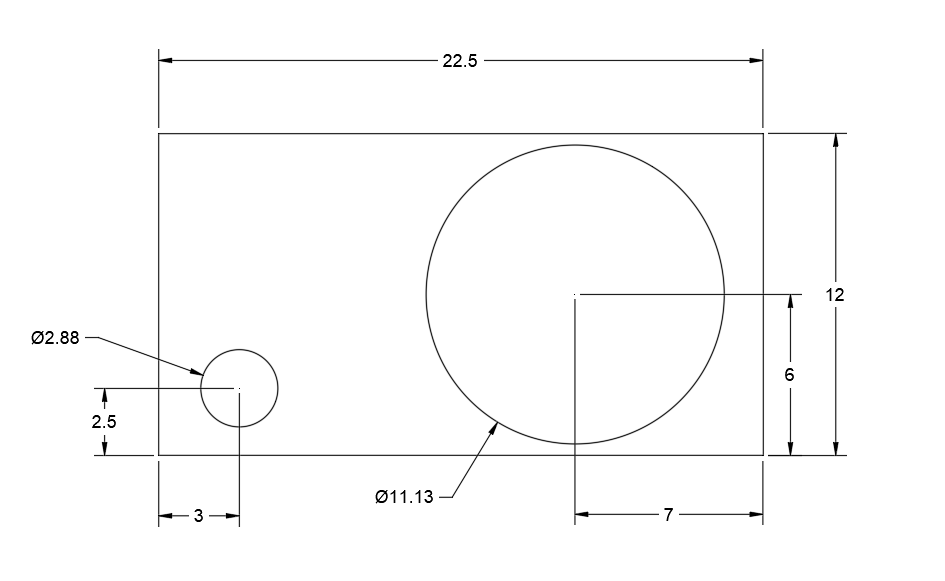
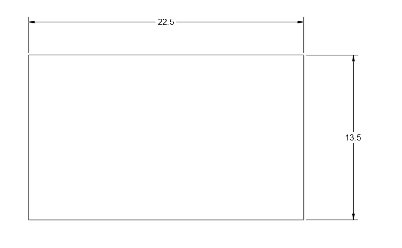
If you chose to sketch your sub box using a 3d modeling program, you can convert the parts in the model to drawings to help during the construction of the box. Having these handy when cutting out the pieces can be extremely helpful, and can help to make sure you don't make any silly errors.
Start Building!
The process and techniques used to build subwoofer boxes are already well documented, so an explanation by me isn't needed. Check out some guides on how to build your newly designed ported subwoofer box and enjoy!