How to Design a Night Lamp in Fusion 360
by tanish satpal in Design > 3D Design
617 Views, 2 Favorites, 0 Comments
How to Design a Night Lamp in Fusion 360
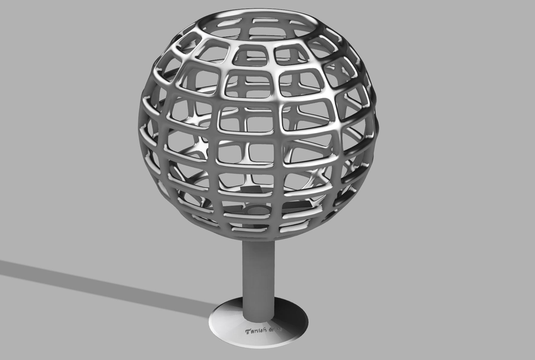
I made a stylish night lamp in fusion 360, and it is actually easier than you think! Try it out with me.
Supplies
All you need is a computer with Autodesk Fusion 360 installed in it
The Sphere
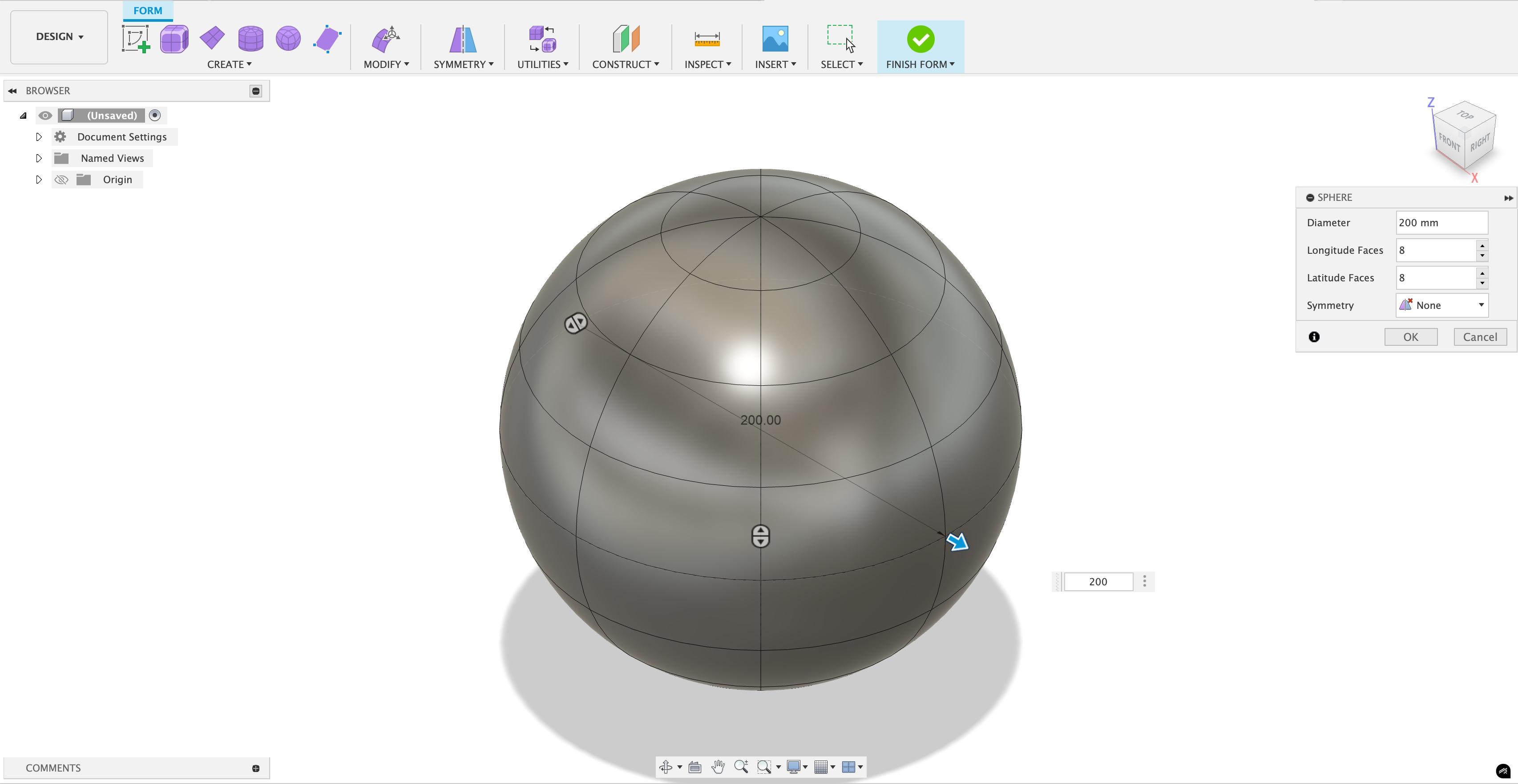
First of all, in the create the top sphere. It can be done by clicking the form/mesh option on the top bar(The icon is purple in colour). Then, you will get a new set of options to choose from. Click on the create Button and from the menu, the option sphere. You will have to choose a plane to make it on, and choose the "bottom plane". Then, at the centre, click your cursor on it. You will see a sphere appear, and you will change its size to 200mm. And, on the right - side menu, choose the number of faces as 12 latitude faces and 8 longitude faces.
Cutting the Sphere
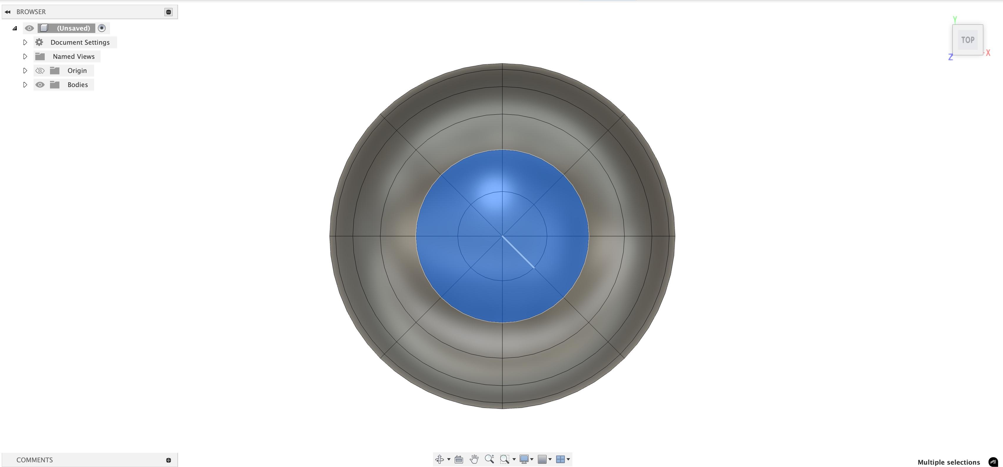
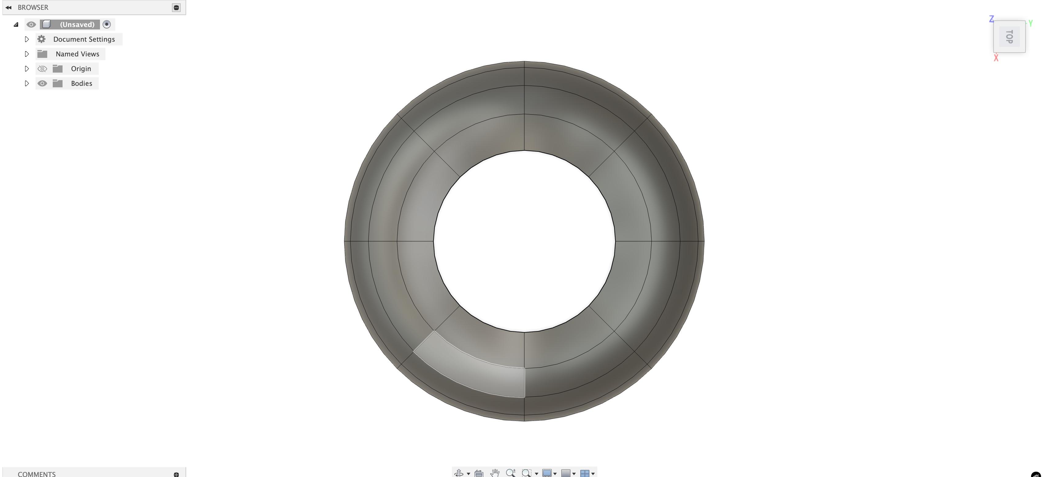
Shift to top view. You will see faces. Control click the faces of the center 2 layers from the top and delete them. Then shift to bottom view using the cube on the top-right corner and do the same for the bottom side too.
Modifying the Cut Sphere
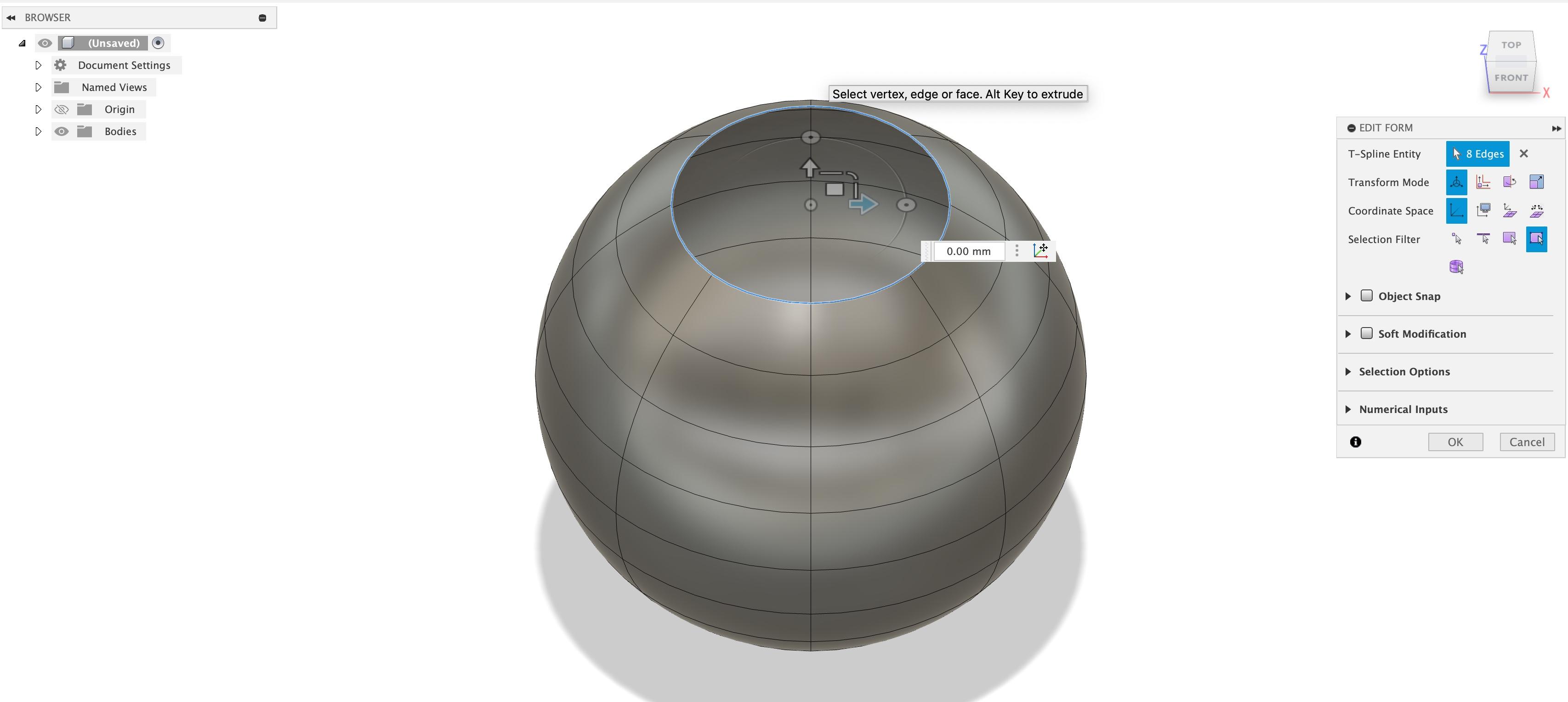
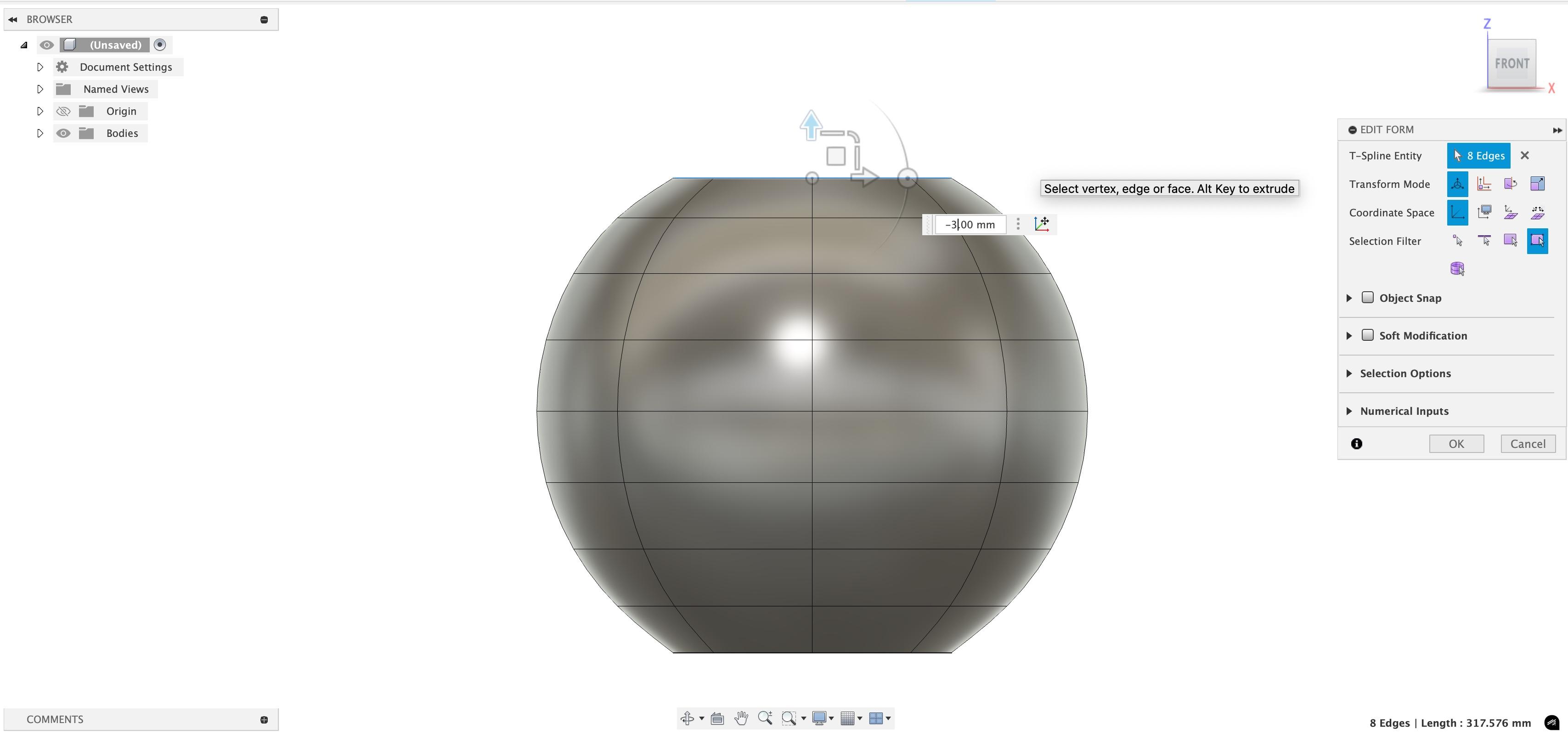
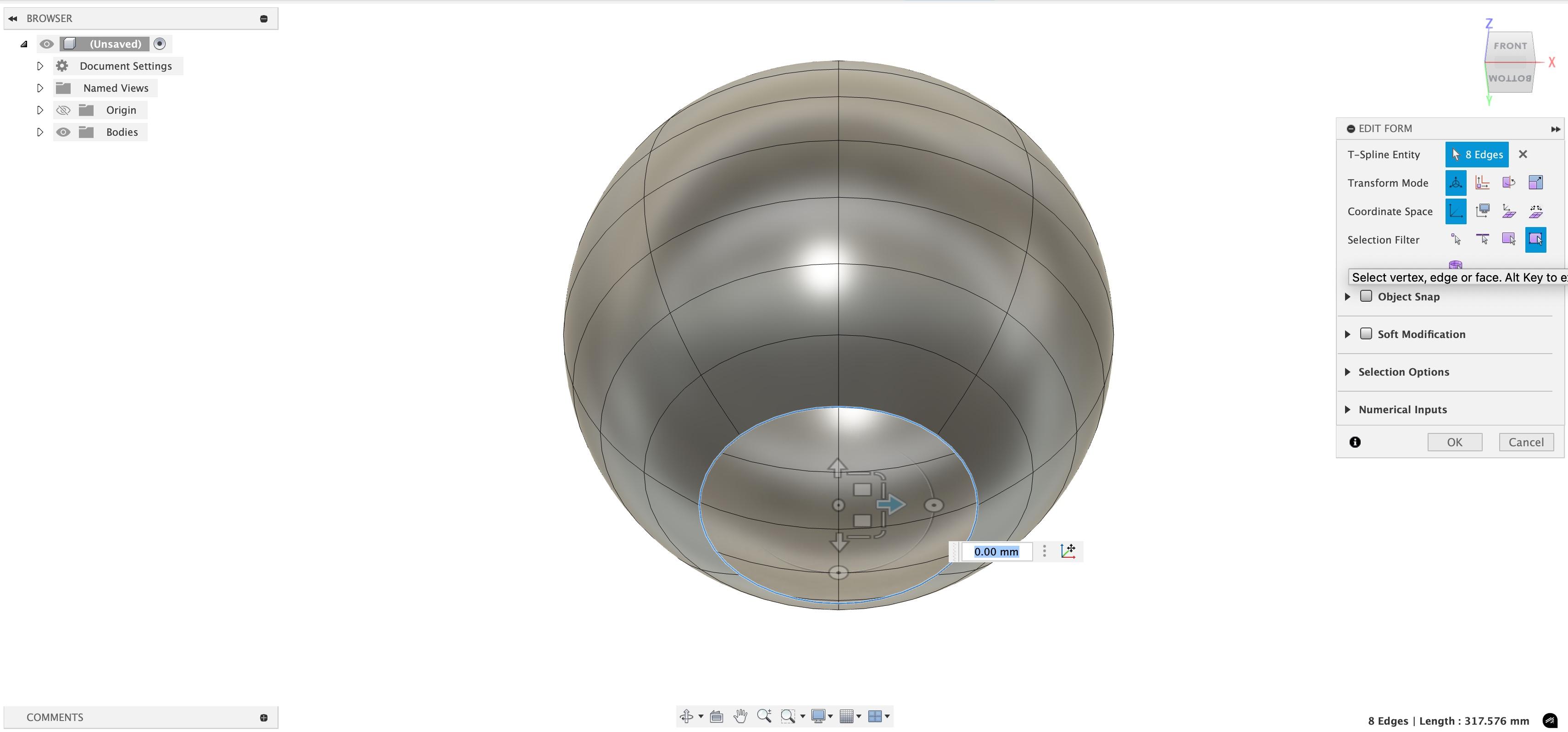
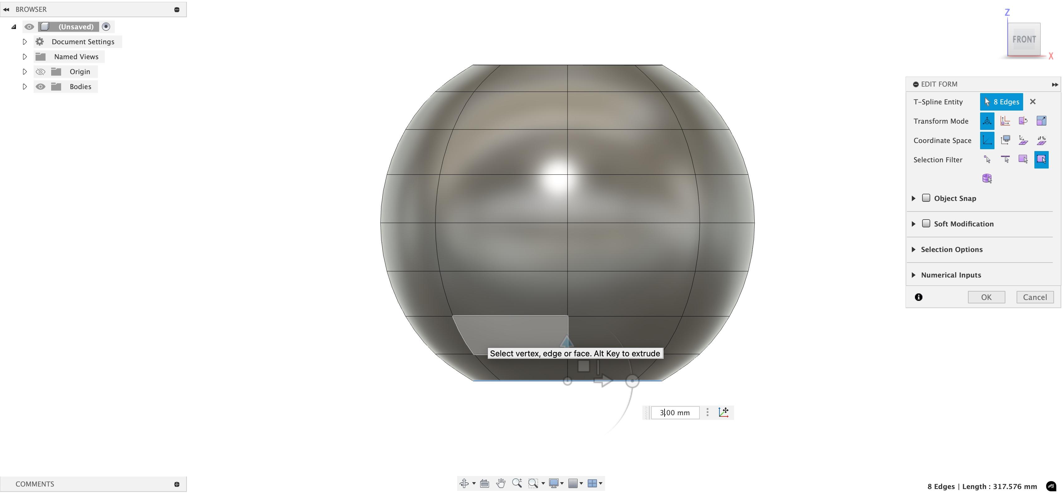
Shift to top-front view. Then, on the top bar, click the option "modify" option. Then hold control and click the top side of the sphere(only the lines). Be careful, as you have to do it for each line. Then shift to front view, and click the up-down arrow. You will also find a text box next to it. Type -3 in it. Do so for the bottom also, but in that, type 3 in it.
Piping the Sphere
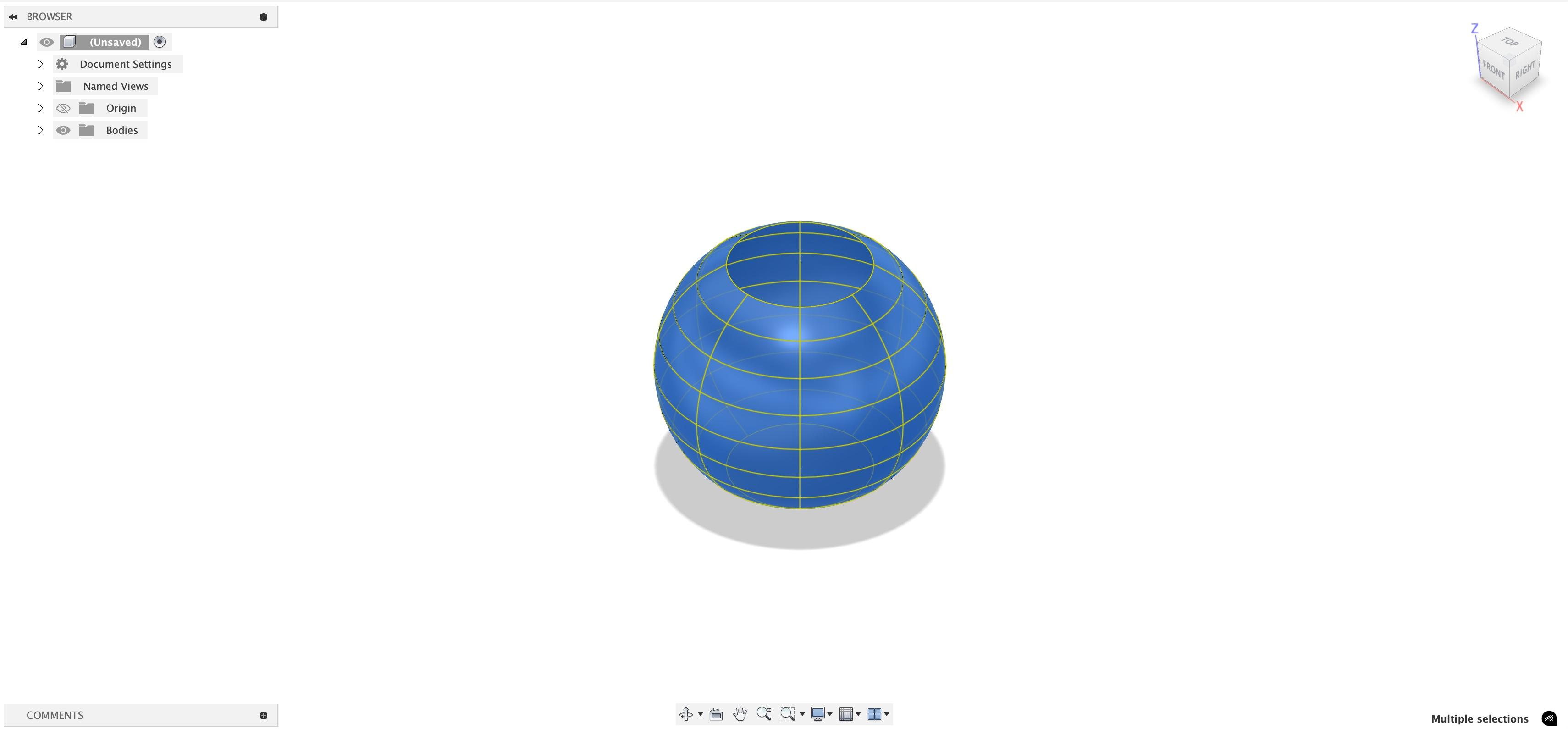
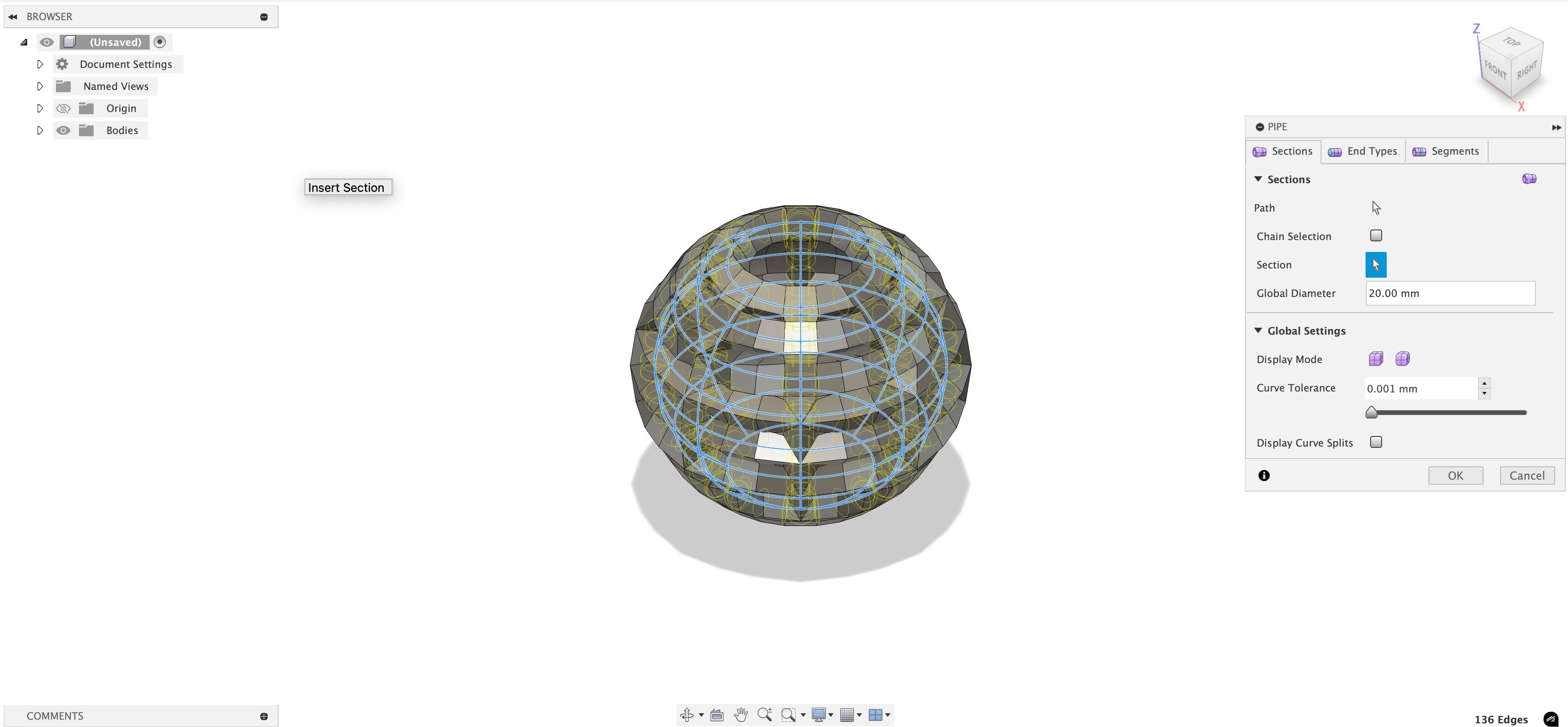
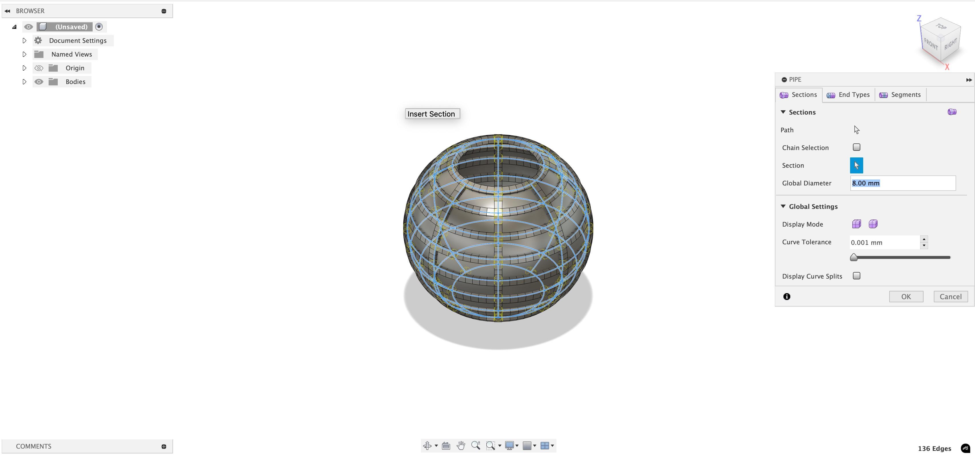
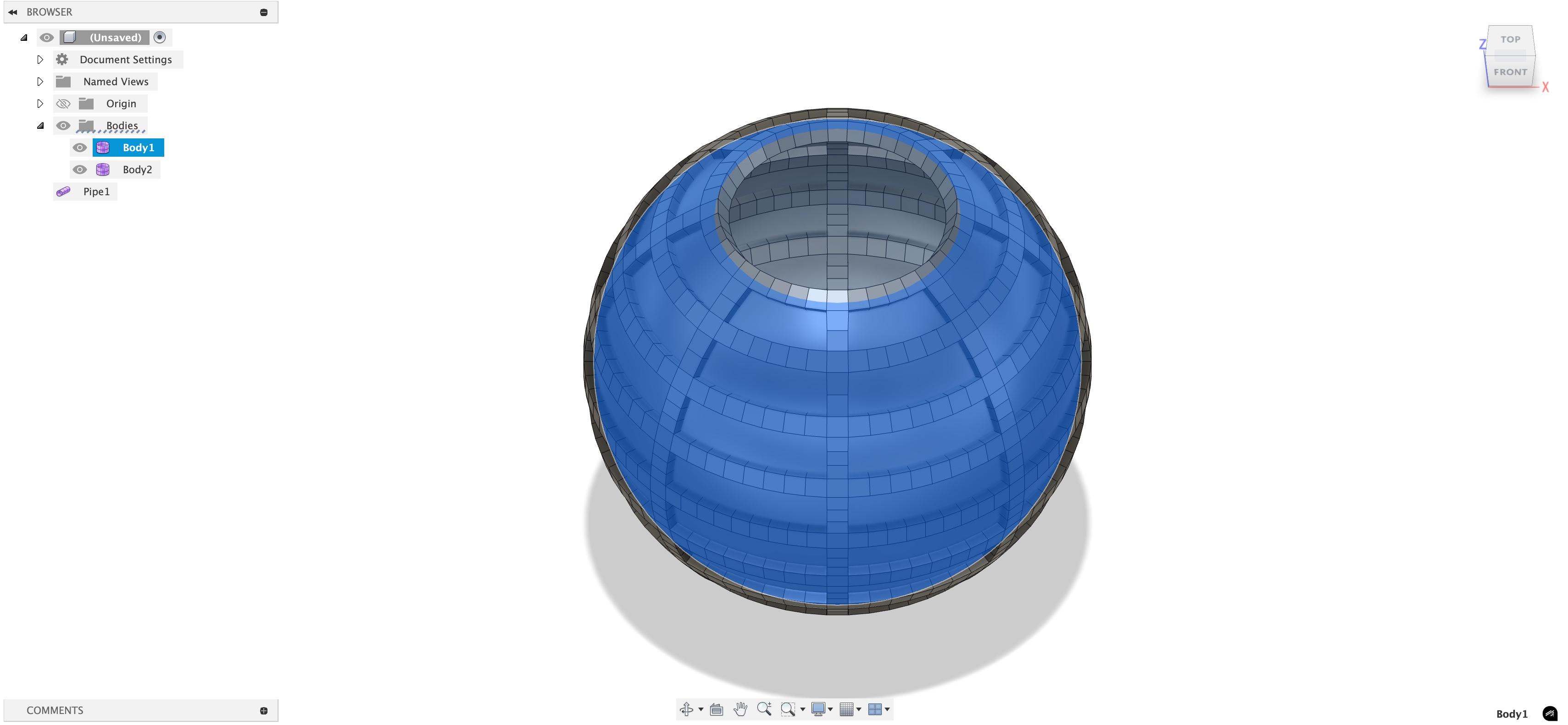
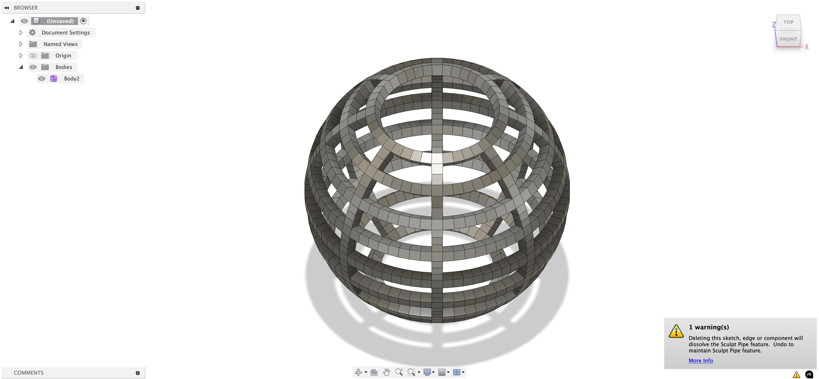
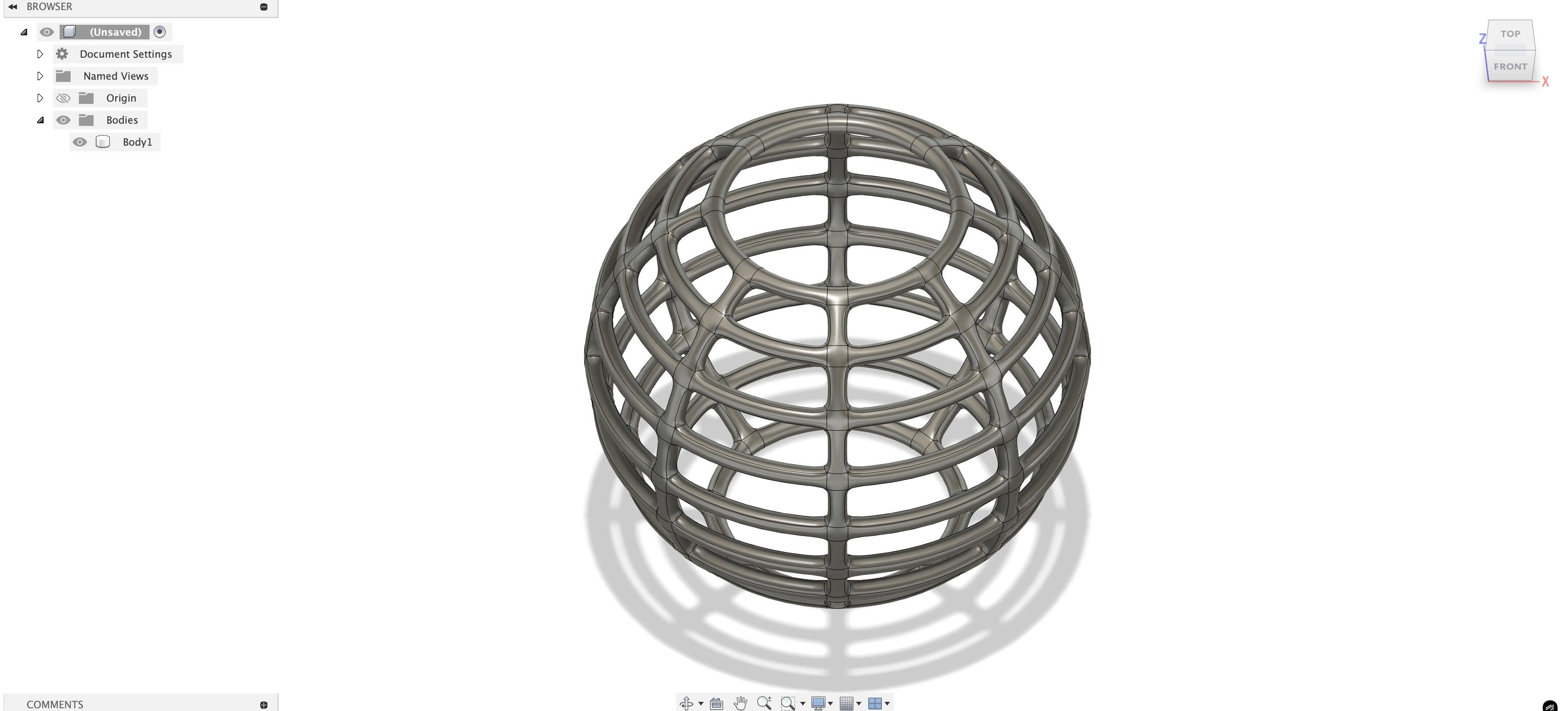
Shift to a view through which you can see the whole sphere. I chose the top-right-front view. Then zoom out and select the whole sphere. Go to create, and this time, choose "pipe". Your sphere will be covered with all sorts of shapes. But don't worry, on the right hand. menu, in the global diameter, write "8" instead of 20. Then, go to the left-hand menu and click the arrow next to "Bodies". You should see "Body 1","Body 2", and "Pipe". Body 1 is the sphere. Body2 and pipe is the layer over the sphere. But, double check it. Click Body 1 and then delete it. Then click finish form. Don't worry if any warning pops up.
Move the Sphere
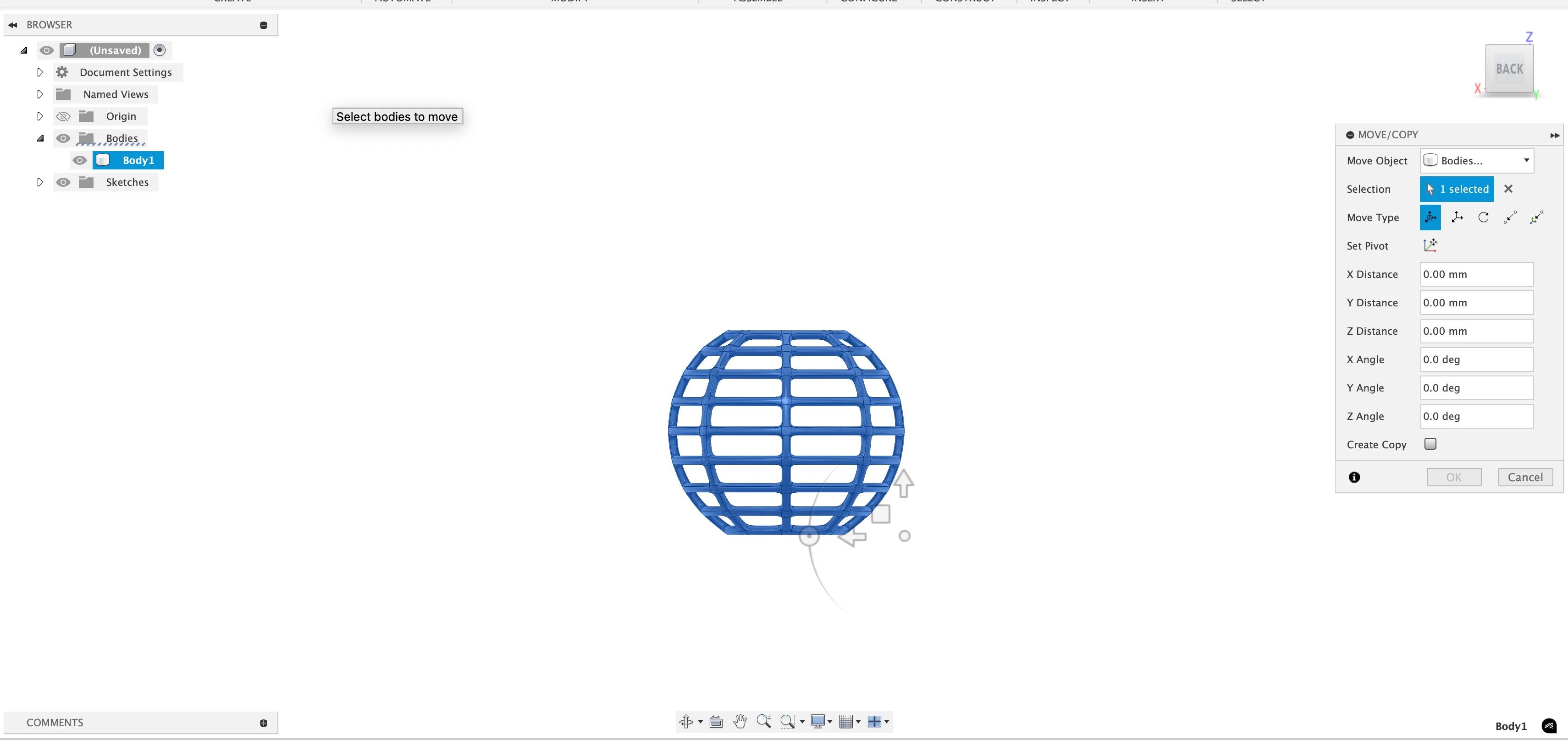
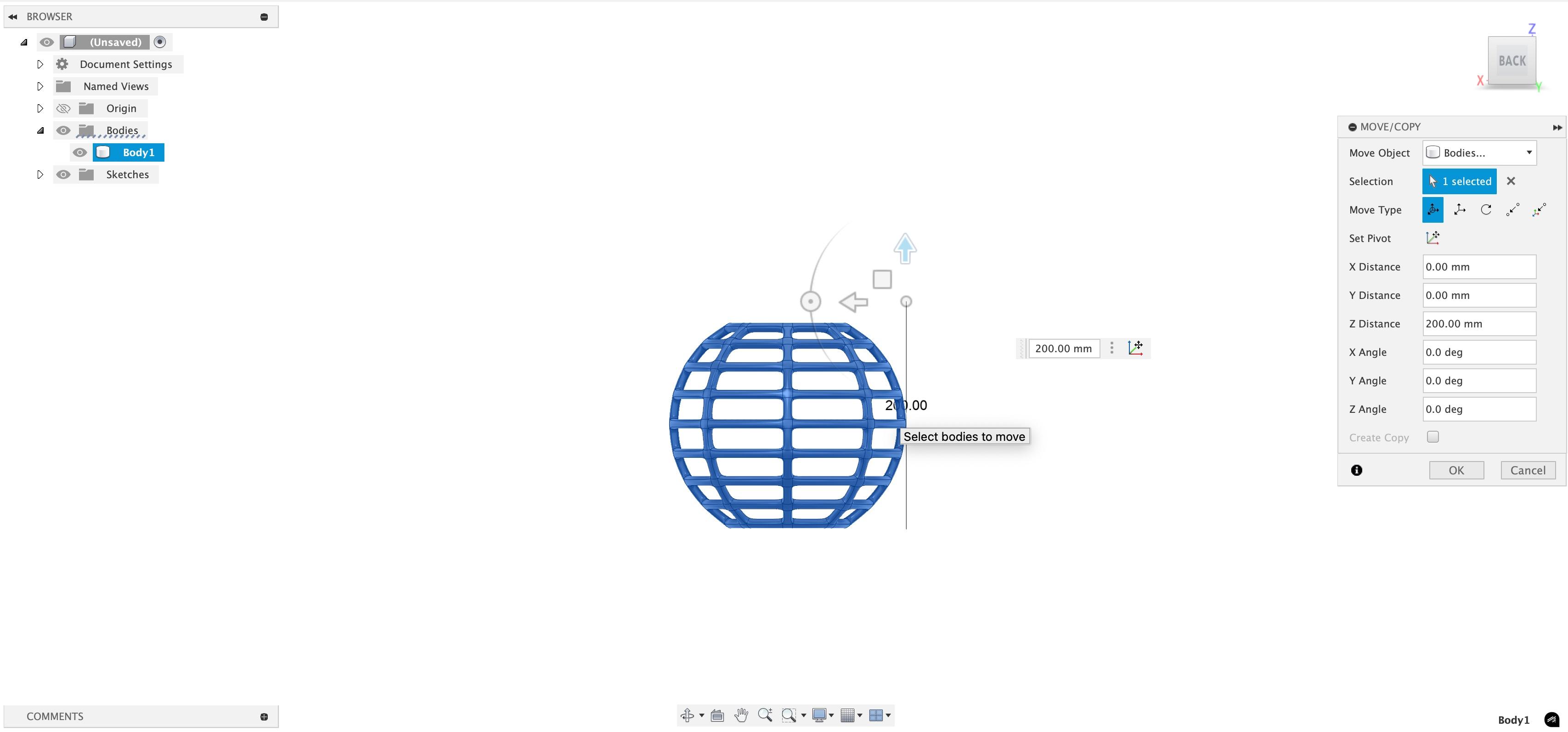
Select the body and click M. Shift to front view. You can now move it upward by 200 mm
The Handle
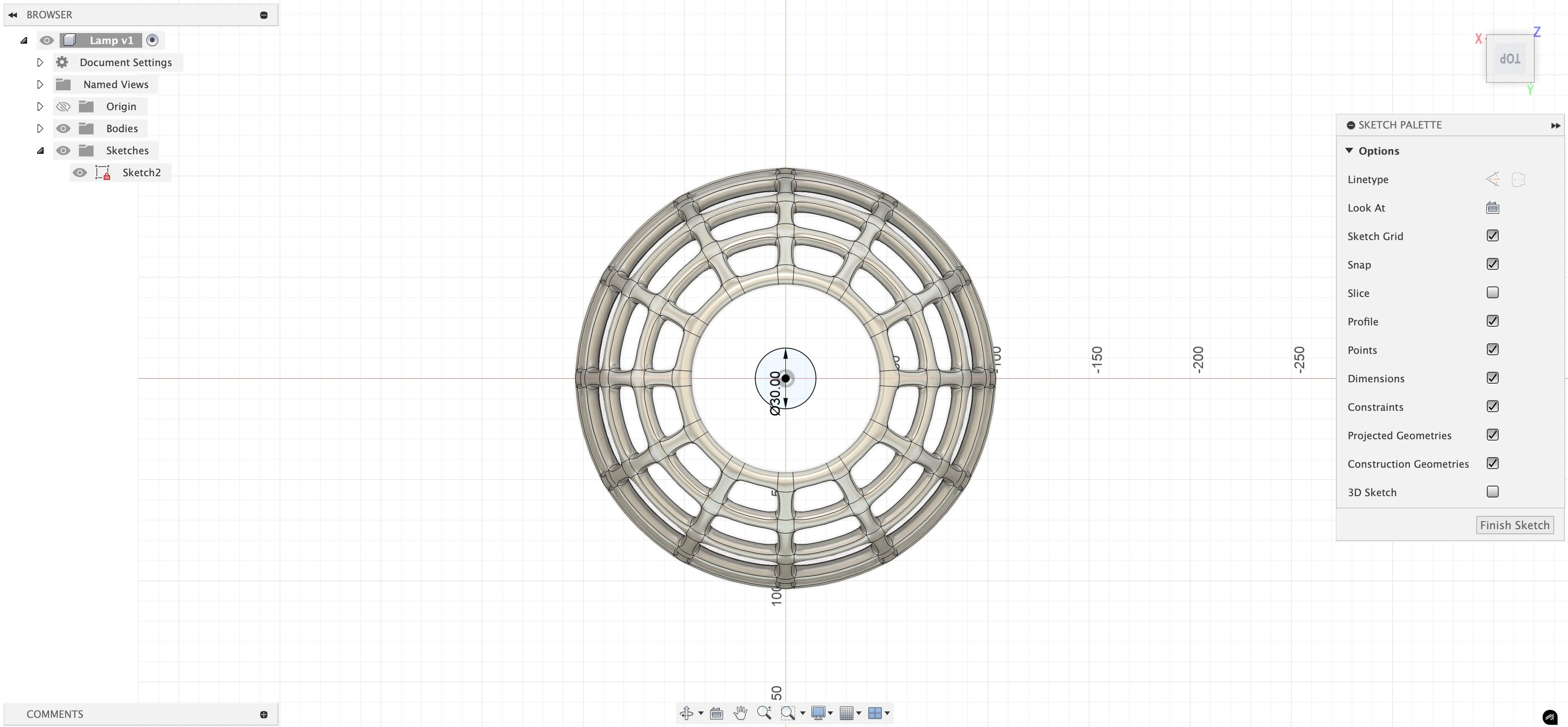
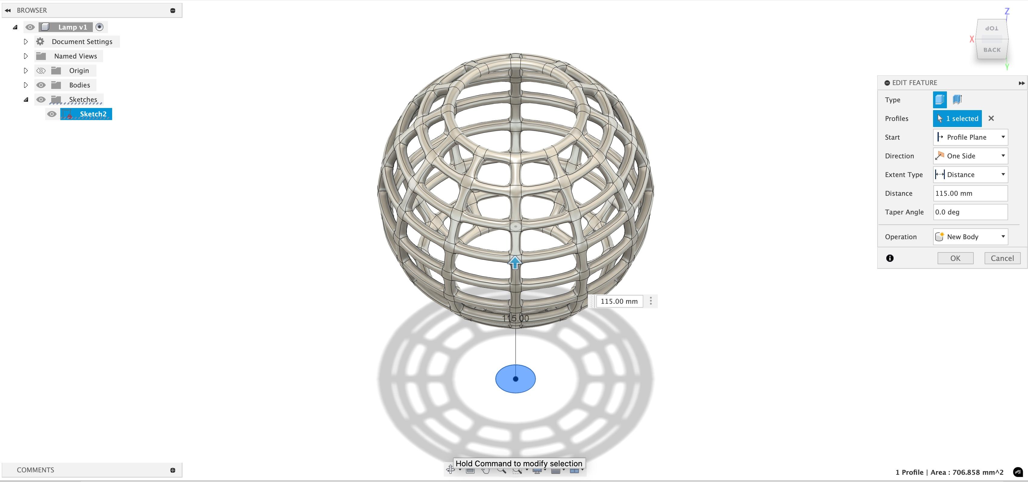
Create a sketch of a circle of 30mm. Extrude it to 115mm(Converts to a cylinder).
The Support
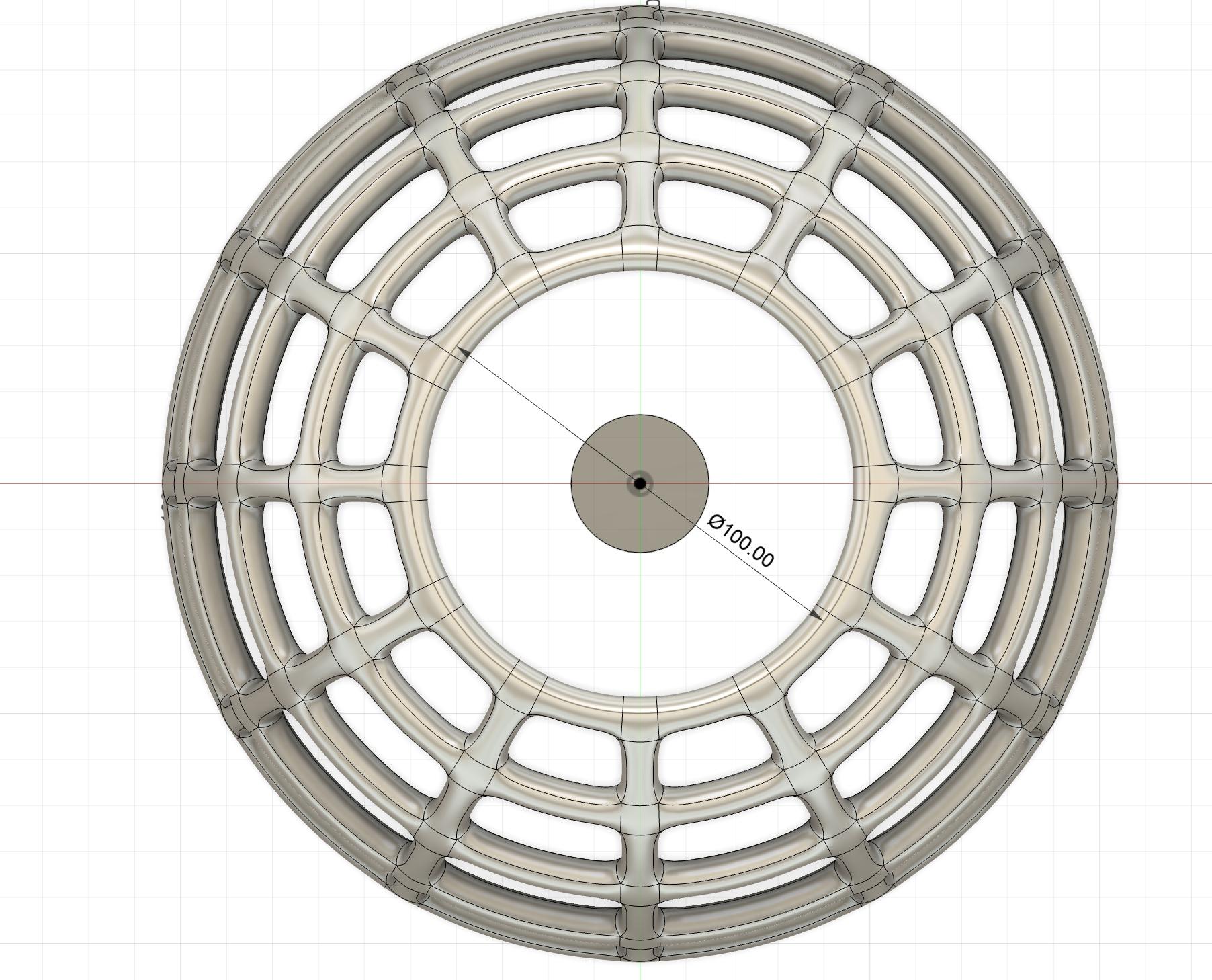
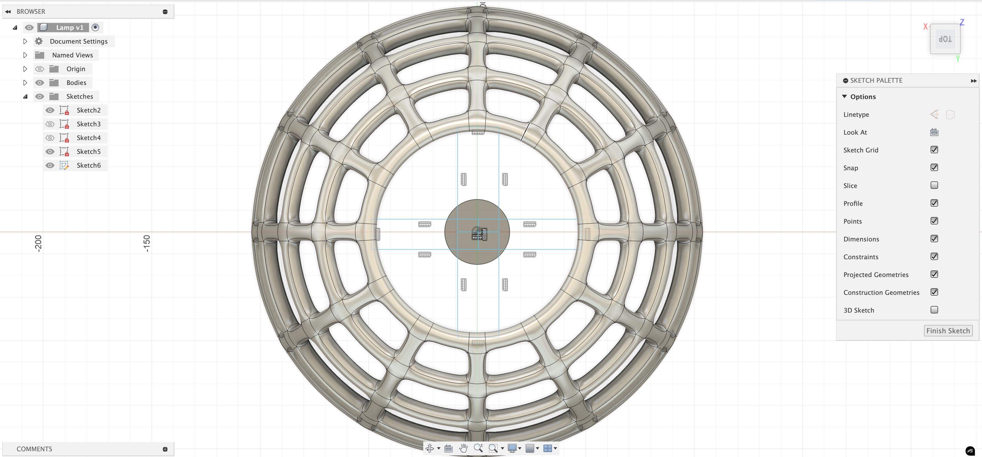
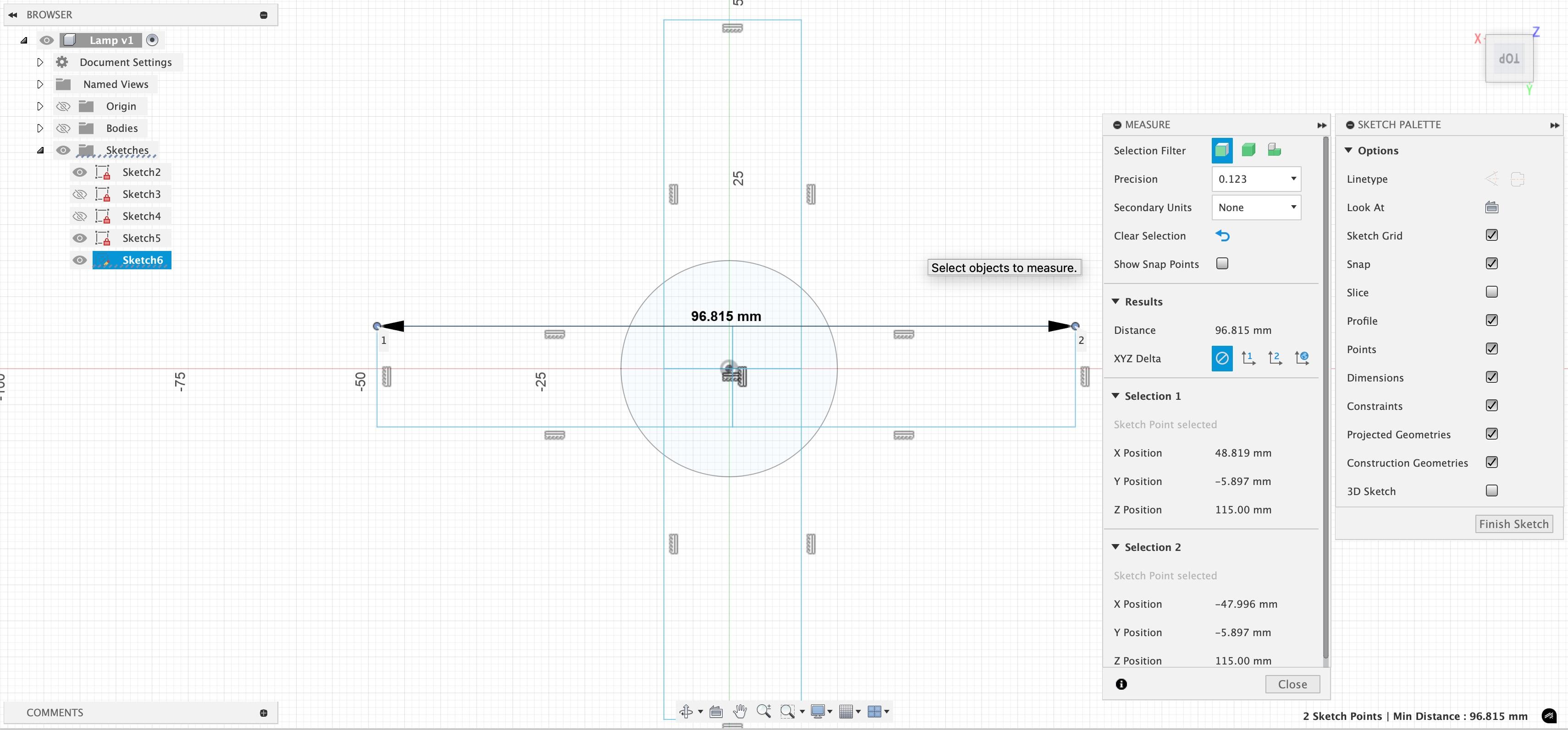
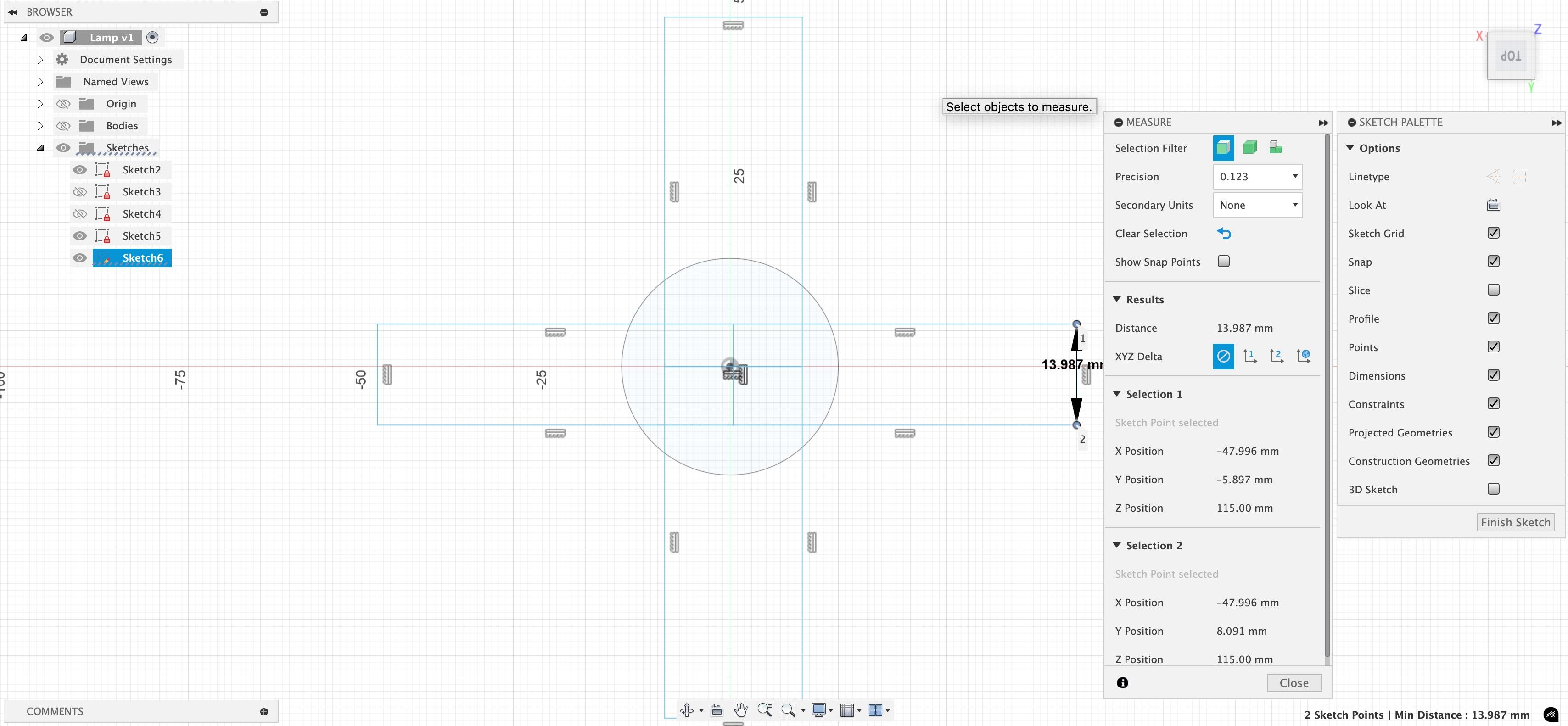
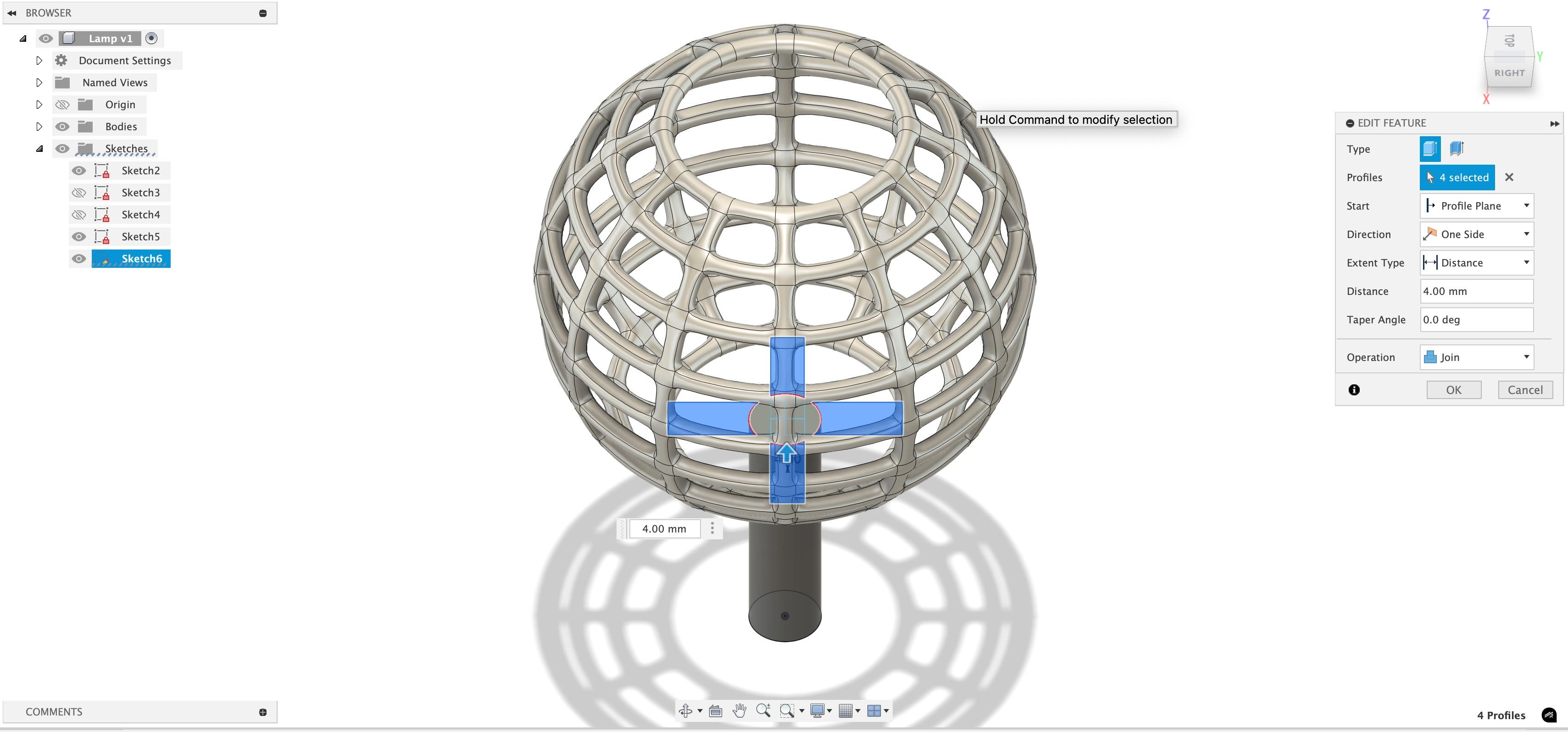
Then, shift to top view and create 3 sketches. All theses sketches will be done on top of the cylinder. One, of the inner circle(30mm), one of the outer circle(100mm), and two rectangles, one left-to right, and one front to back.(97x14mm). Then, extrude the outer parts of the rectangle by 4mm,(select the parts outside the circle)
Hollowing the Cylinder
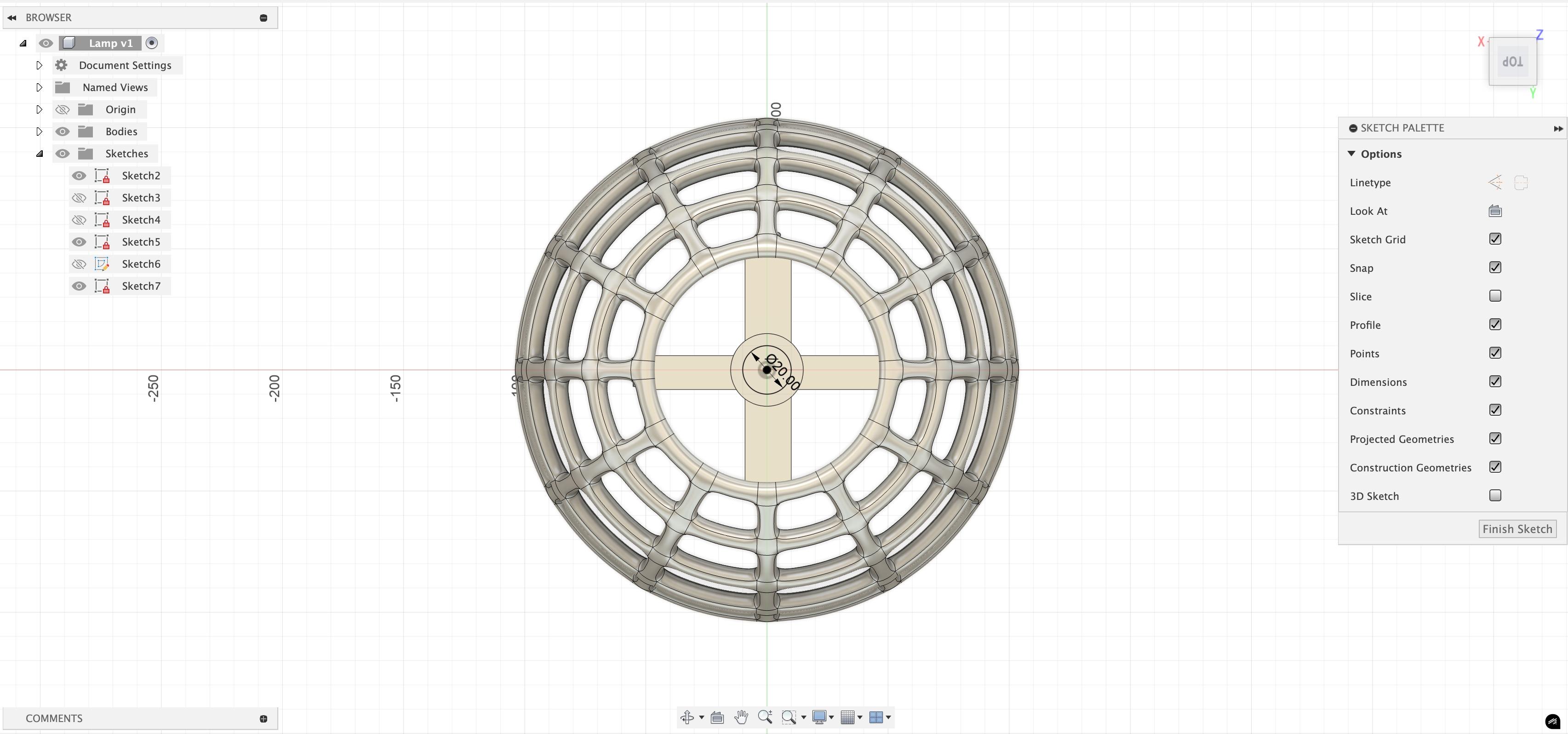
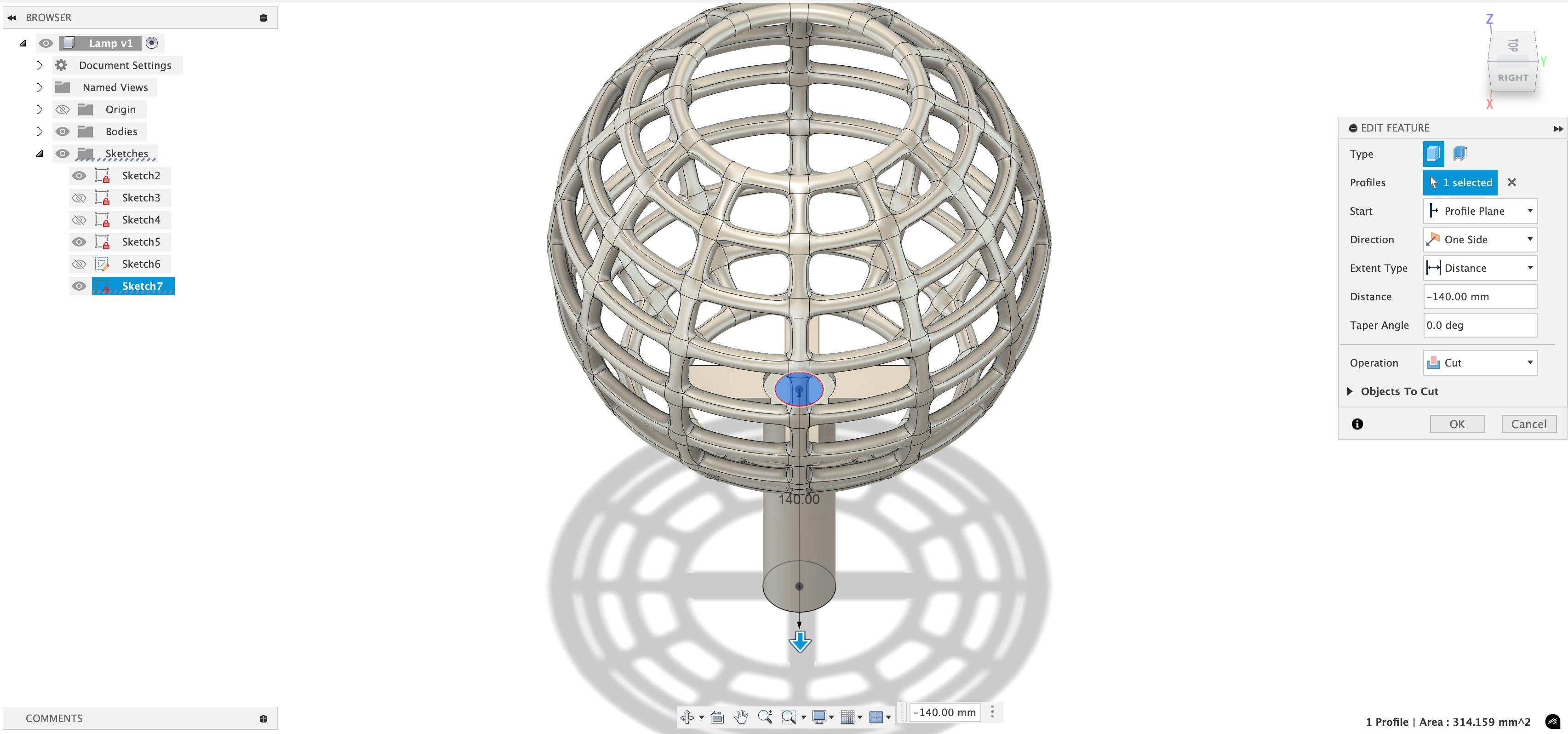
Create another sketch on top of the cylinder, just with a diameter of 20mm. Then extrude it by -140mm, making sure it cuts through the cylinder.
Creating a Hole
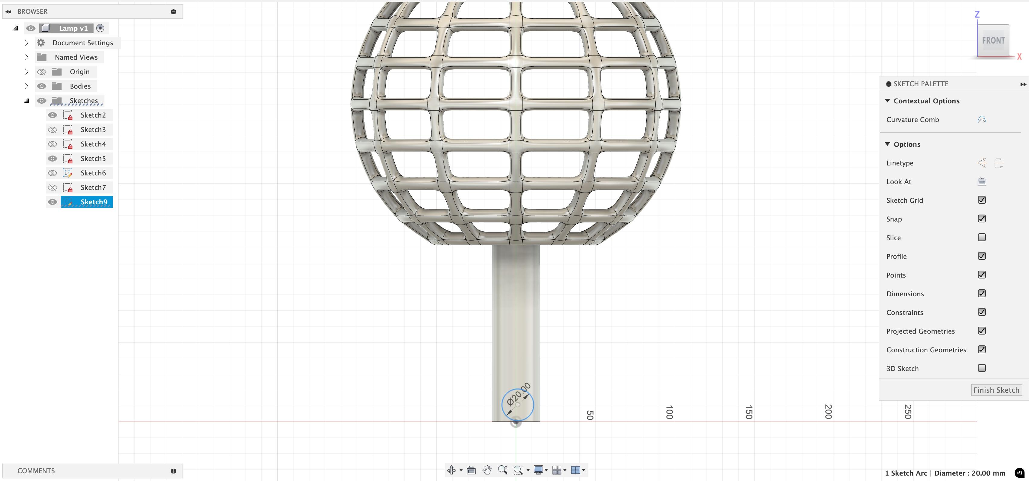
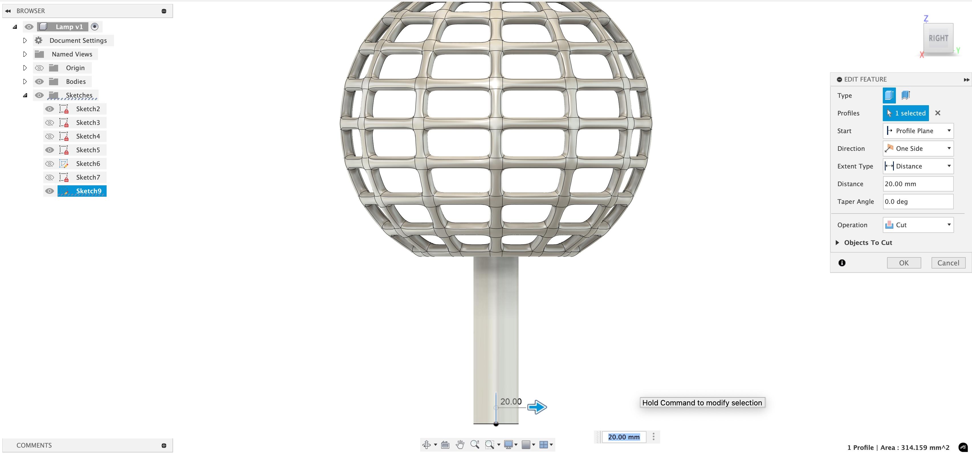
Now, make a sketch using the front axis.It will be a circle, slightly above the bottom and having a diameter of 20mm. Then extrude it by 20mm (it will be sideways) and make sure it cuts through the cylinder
Bottom
.jpeg)
.jpeg)
.jpeg)
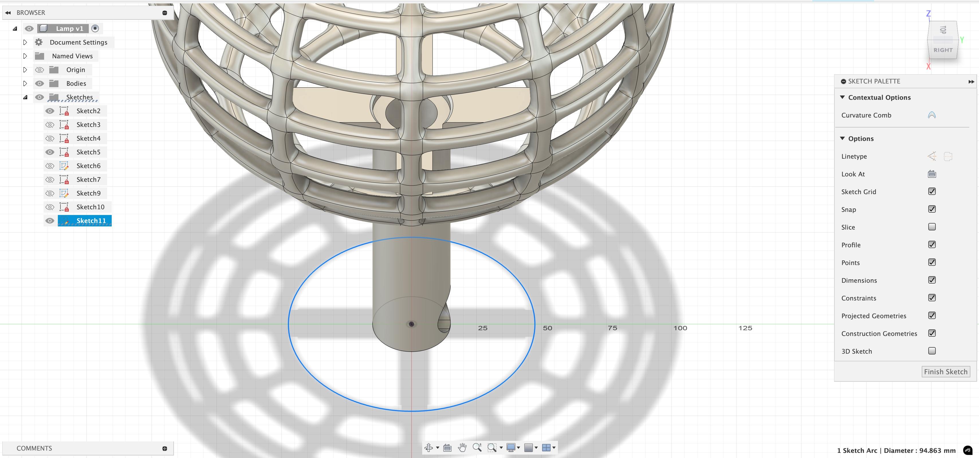
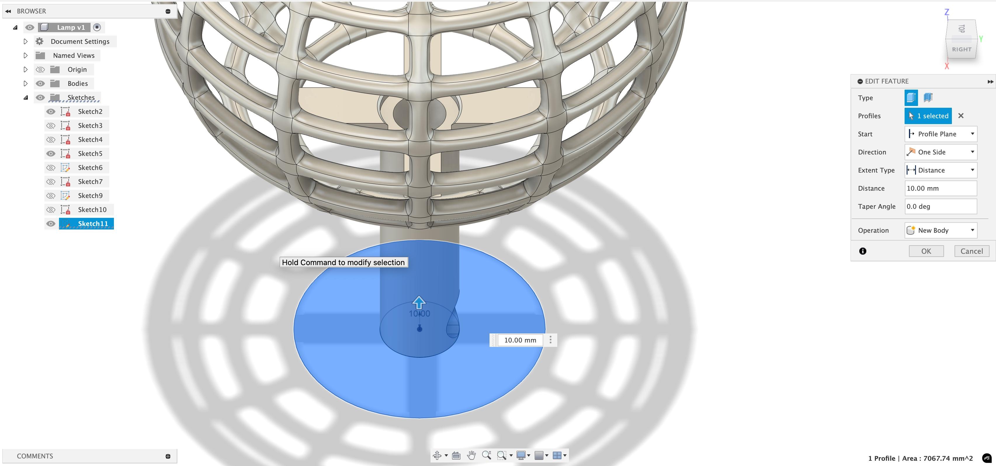
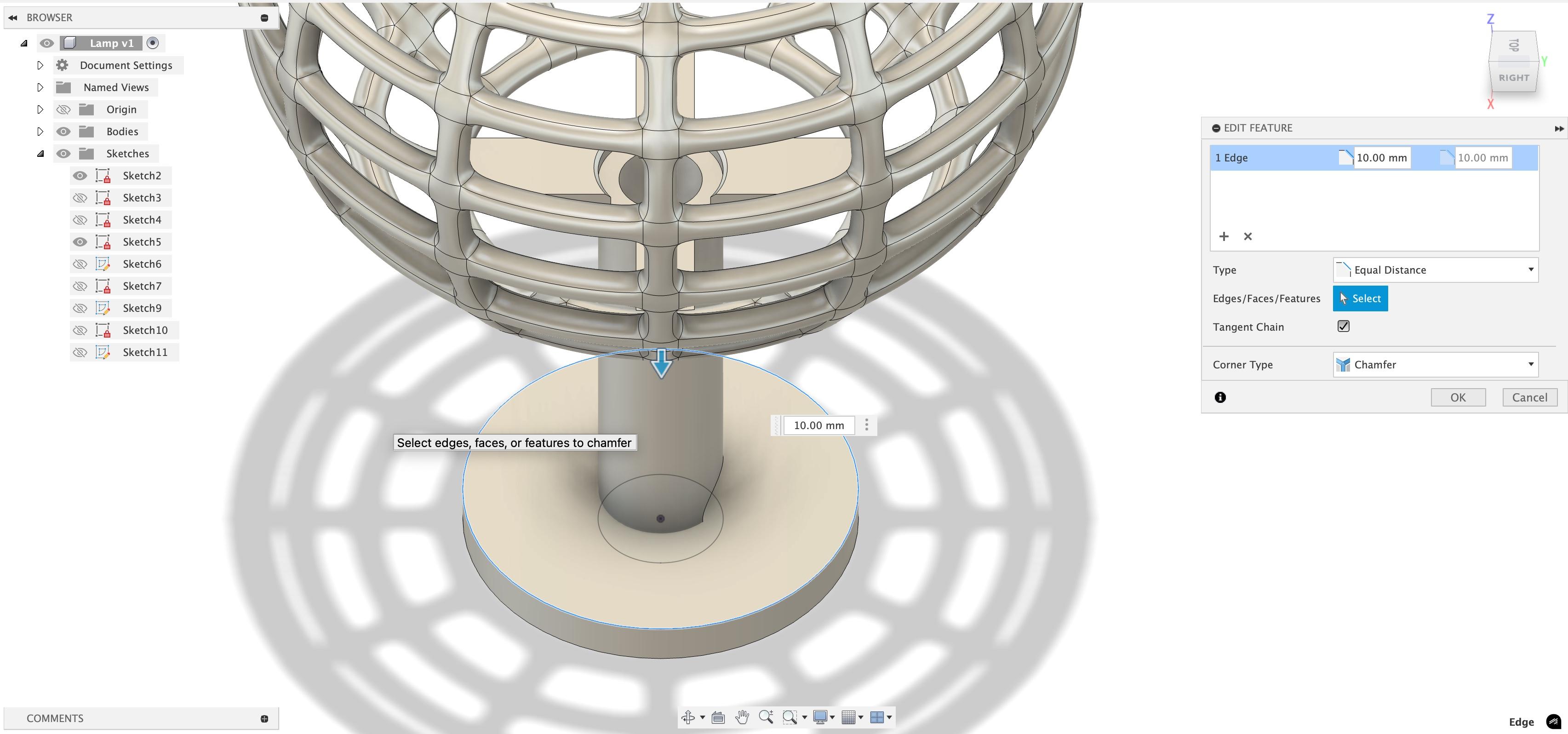
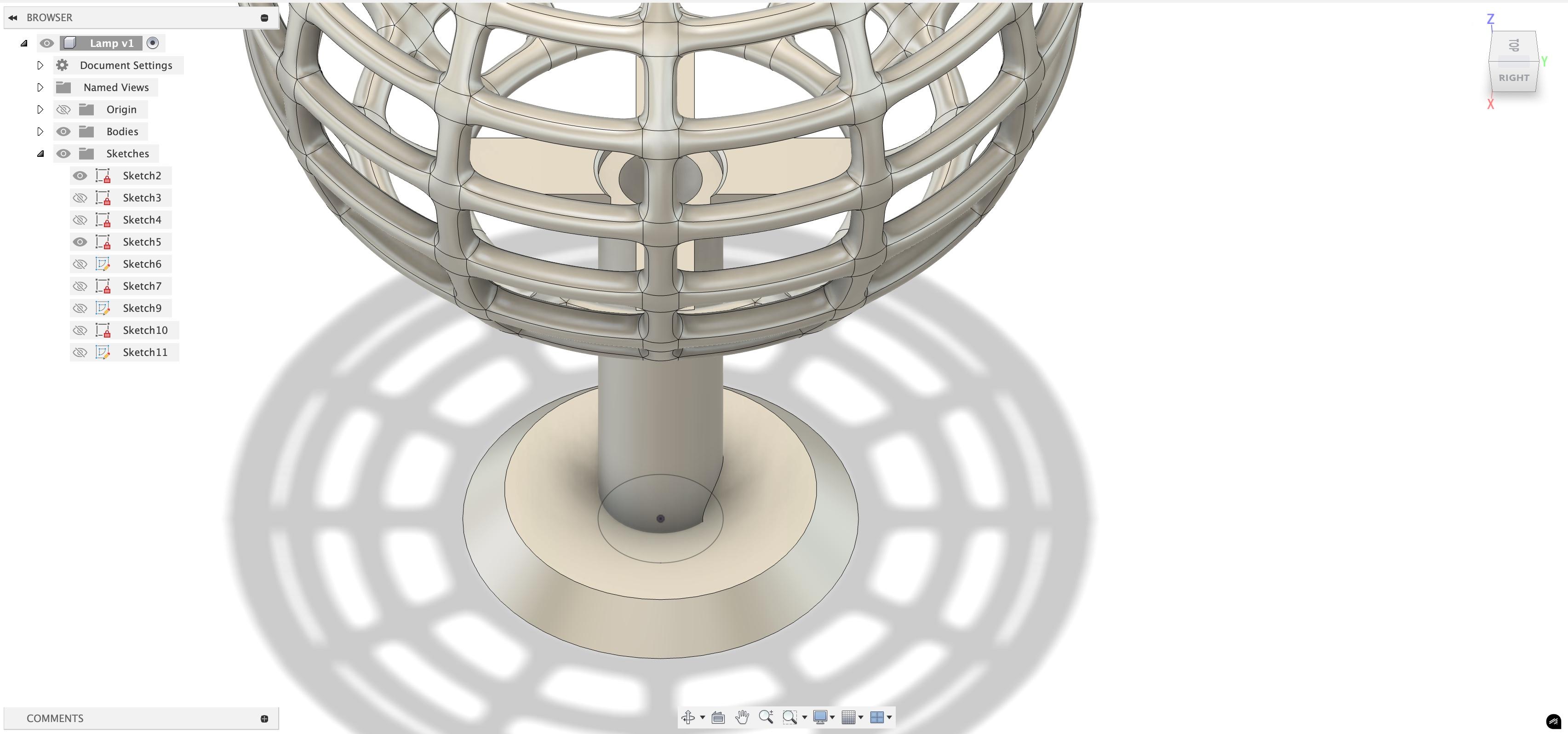
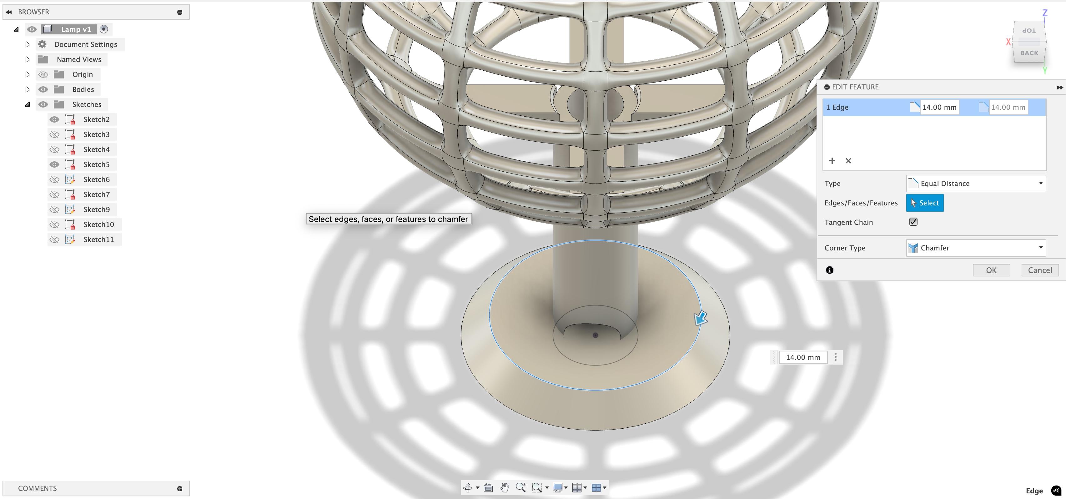
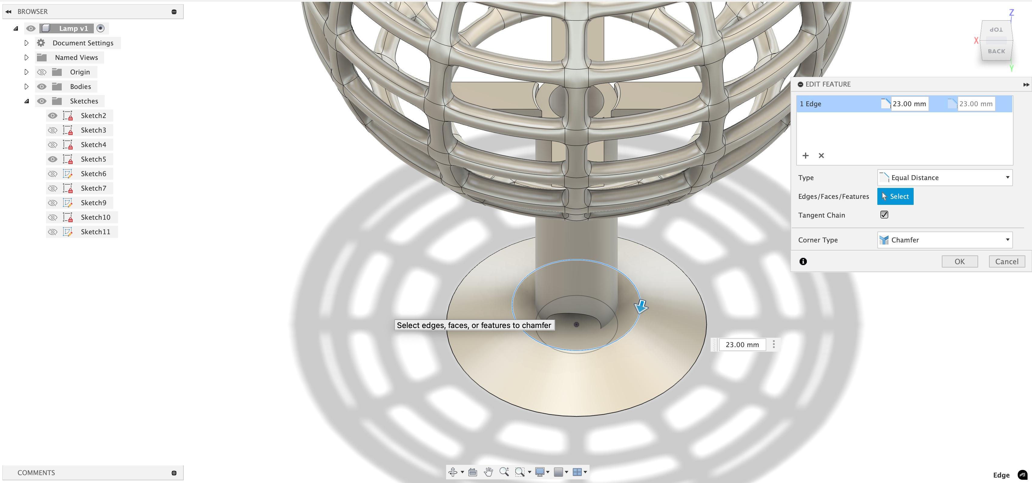
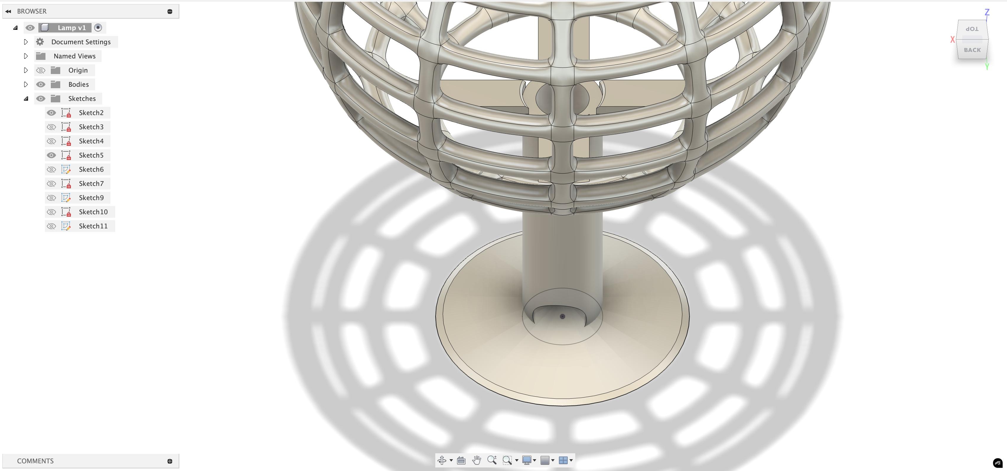
Create a sketch of a circle of 95mm at the centre-bottom. Then extrude it by 10mm. After that, click the top side and use the chamfer function(in modify) to chamfer it by 10mm downwards. Then do the chamfer on it once more by 14mm, and one last time by 14mm.
Naming It (Optional)
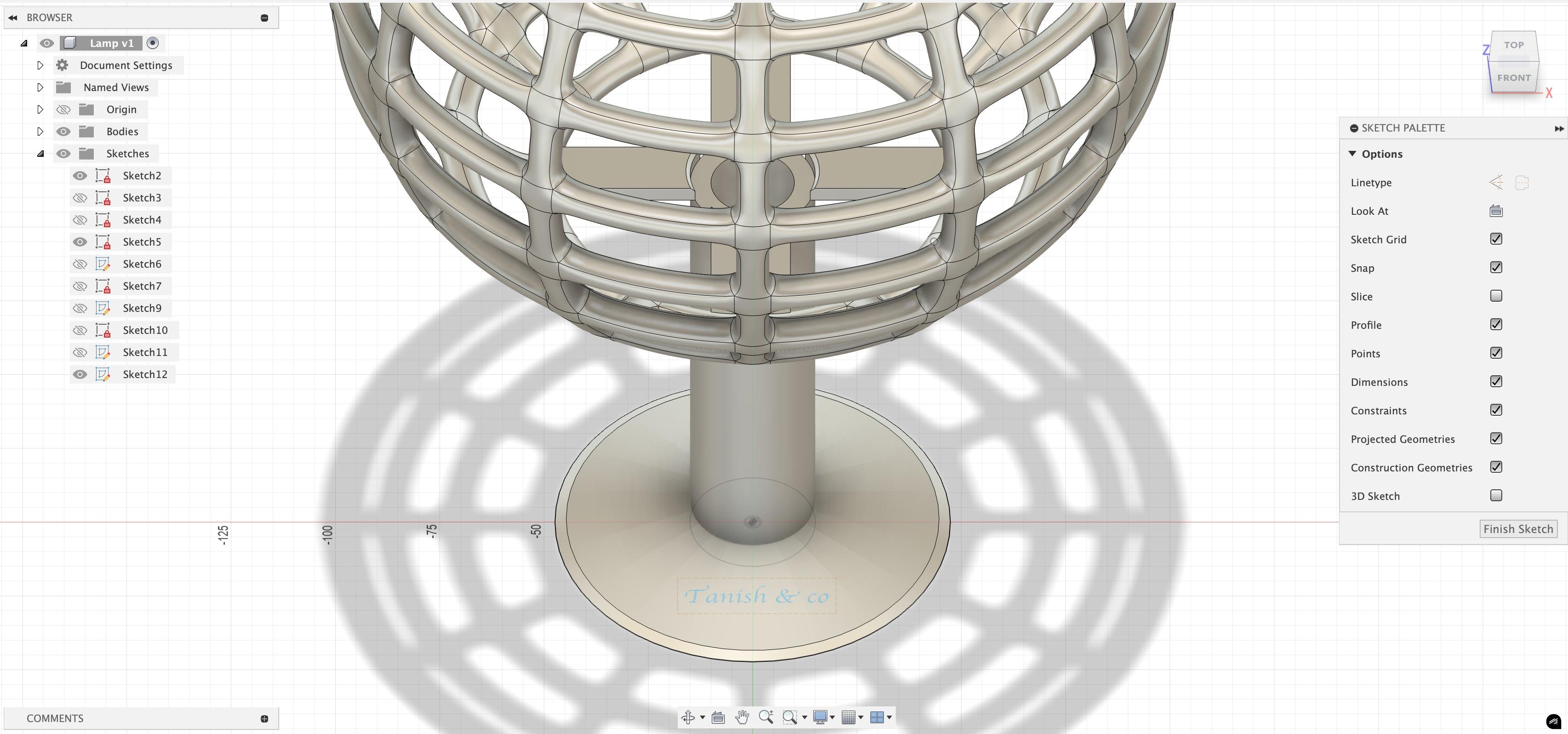
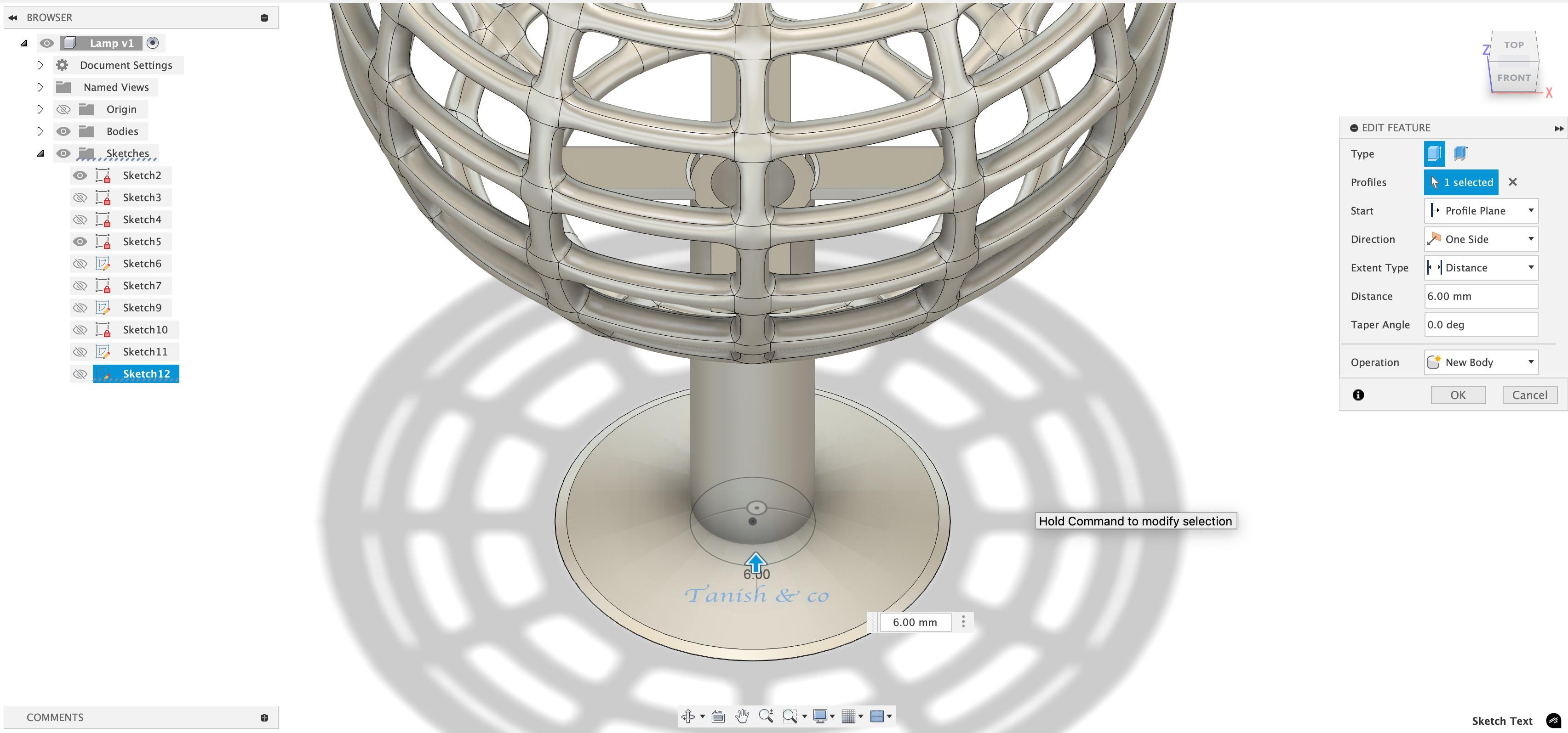
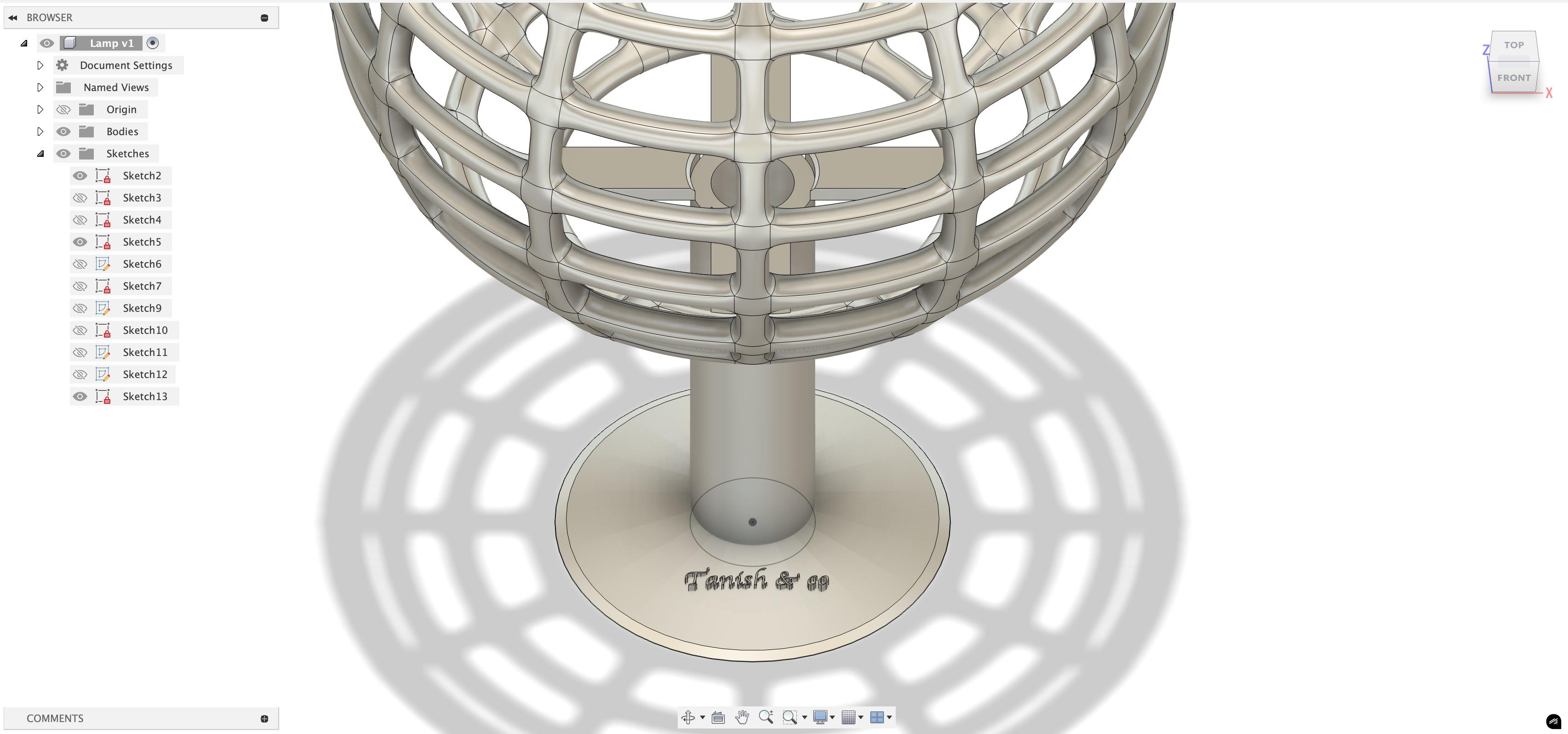
Well, in the end, I usually name my stuff. So, open a sketch and create text with whatever you want to name it. Use your font style (there aren't any good one) and make sure it isn't outside the bottom disk. The, extrude it upwards by 5.5-6mm. Make sure it is a new body or joint to the bottom disk. Cut might also work, but hey, give it a go too!
The End
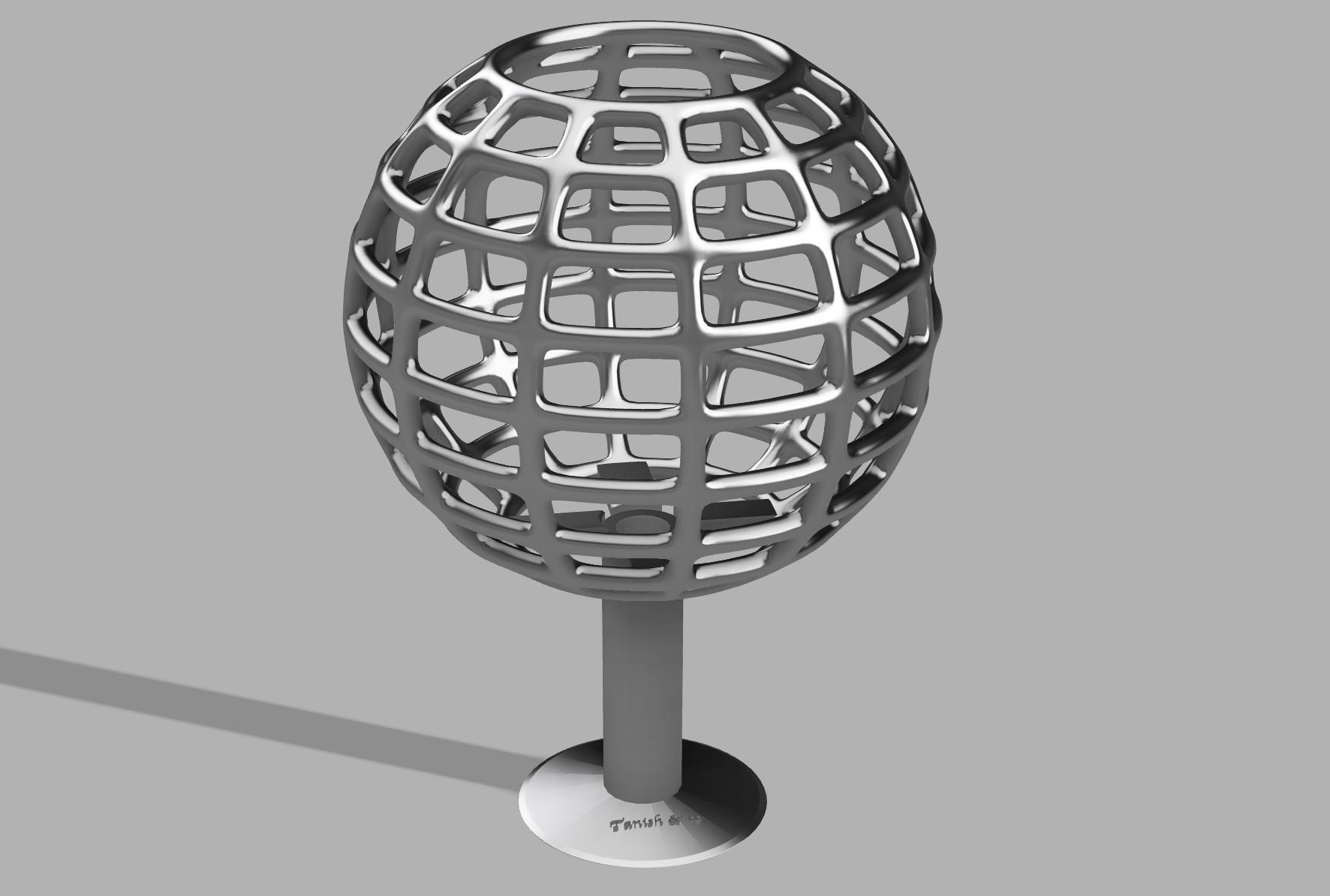
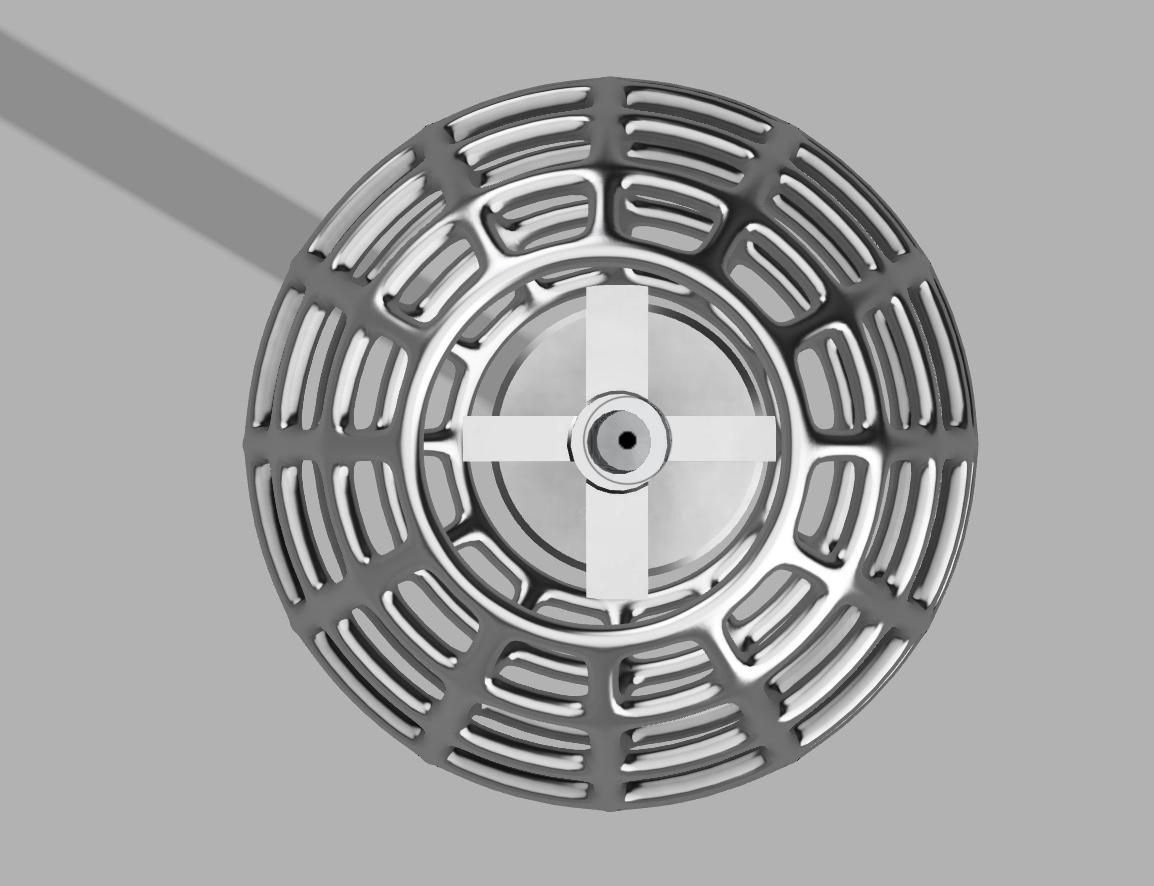
And thats it! You can 3d print it and place a bulb in it too! You can even model a bulb in the 3d model like in it! Please feel free to share your versions of the model! I will leave the stl format of the model as reference for you all. Till then, bye!