How to Design a Button Box Housing With Schematic and PCB
by Pro_Maker in Circuits > Gadgets
9672 Views, 107 Favorites, 0 Comments
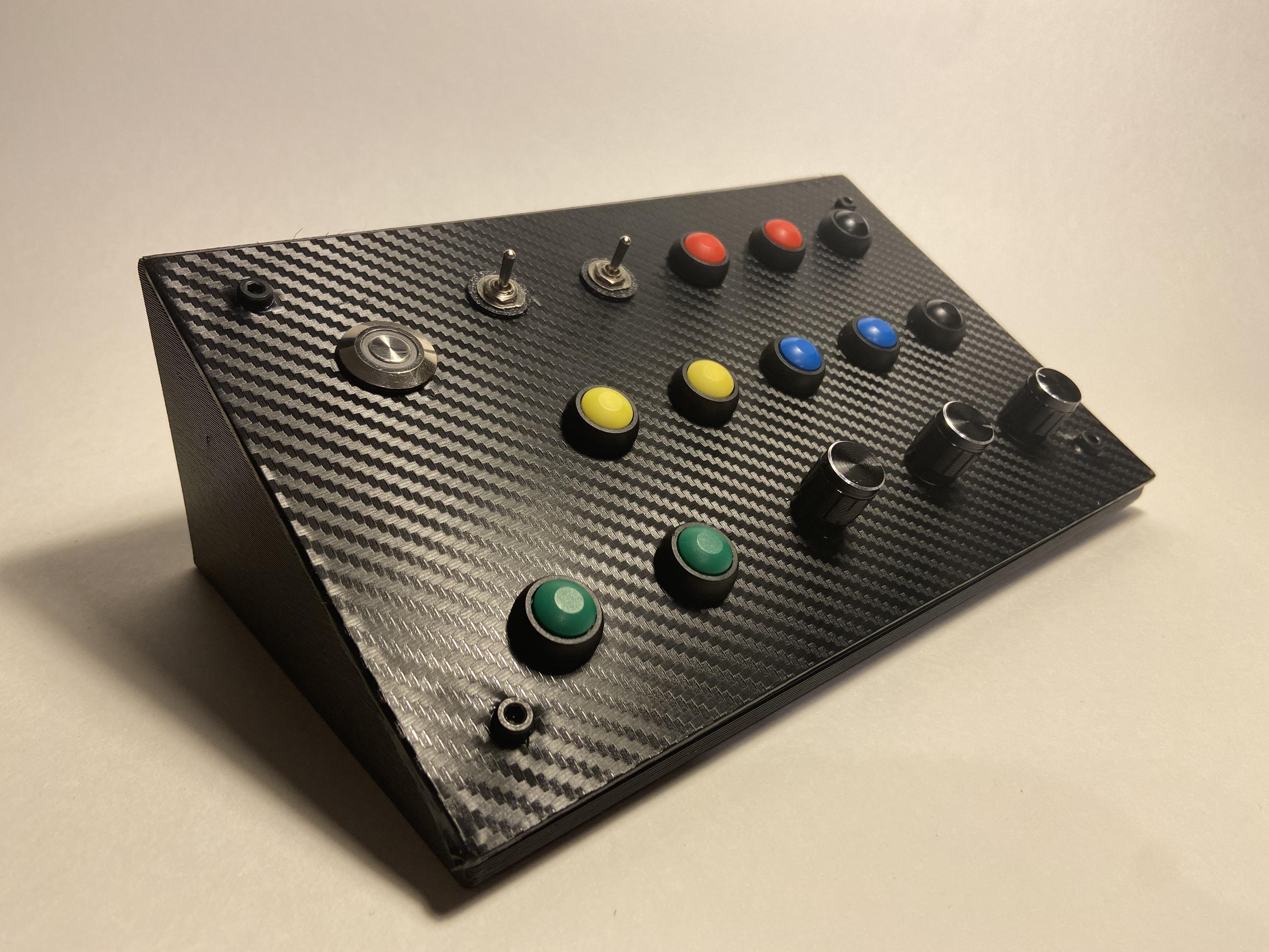
How to Design a Button Box Housing With Schematic and PCB
.png)
A couple months ago, I started a project on Tinker CAD, this would later become my fully working Button Box that I now regularly use in sim games and even for shortcuts in Fusion360. Up to my Tinker CAD project, I had limited skills in CAD and electrical design. After some time researching, I consider myself abled in both CAD design and electrical design (By no-means am I a professional so please take this advice with a grain of salt and feel free to let me know of any errors or improvements). For this Instructable, I will be trying to teach you the skills to design your own Button Box, as opposed to a set-in-stone final product, so my final product may look a little different than my examples.
For this Instructable, I recommend some exposure to Fusion360 or CAD software as I do not go in-depth on the basics of CAD.
Some skills you can expect to learn in this Instructable are:
- How to utilize Parameters in Fusion360 to create your Button Box Housing
- How to create your own schematic for your own button box
- How to utilize your own schematic to create a schematic in Fusion360
- How to create your own electrical library for your schematic in Fusion360
- How to transform a schematic in Fusion360 to a PCB
- How to Auto-Route nets for your PCB
Unfortunately, I will not be teaching you to code your button box, as I do not yet feel comfortable in sharing code that I've designed. I have just started coding and do not want to damage or hurt anyone, but you can refer to the Additional information section at the end of this Instructable for some great coding resources.
Supplies
Some Buttons, Switches, and Encoders to think about using for your Button Box:
- Momentary Push Buttons (12MM) -- Amazon
- Momentary 2 Position Rocker Switches -- Amazon
- Rotary Encoders (5 Pin) -- Amazon
Supplies you should remember:
- Screws M4x14 -- Amazon (I used metric because metric heat set inserts are most common)
- USB - USB Micro -- Amazon (For use with Arduino Pro Micro)
- Brass Heat Set Inserts M4 -- Amazon
Special Notes or Comments:
I recommend beginners in Arduino/electronics to start with an Arduino Leonardo because it pretty easy to protype designs using a bread board without soldering, but you can use an Arduino Pro Micro if you feel that you are good with soldering.
If you are going to use a 3D printer to create you Button Box Housing, I recommend using PETG filament for its strength and ease of printing qualities
Lastly, I used Carbon Fiber Vinyl for my Button Box Lid, but this is purely aesthetic.
Where It Started

My project started a couple months ago as a simples design in TinkerCAD, and I was waiting to learn some new skills that I would be able to apply once I started designing in Fusion360. I have to say, now that I have started using Fusion360, it has open many doors to all sorts of cool designs that I was not able to do in TinkerCAD. So, after learning some skills in Fusion360, I decided I would make this project that has been put aside for some time and make it my first purpose made design in Fusion360. So, as I talk about some skills for the duration of this Instructable, keep in mind that I am learning alongside you and that you can also learn some skills from additional resources. You can refer to some great resources for learning CAD and designing your own Button Box on the final "Step" of this Instructable.
Creating a Schematic for Your Button Box
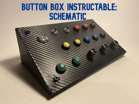
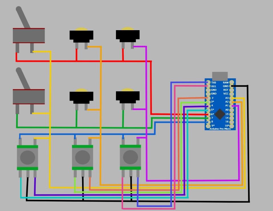
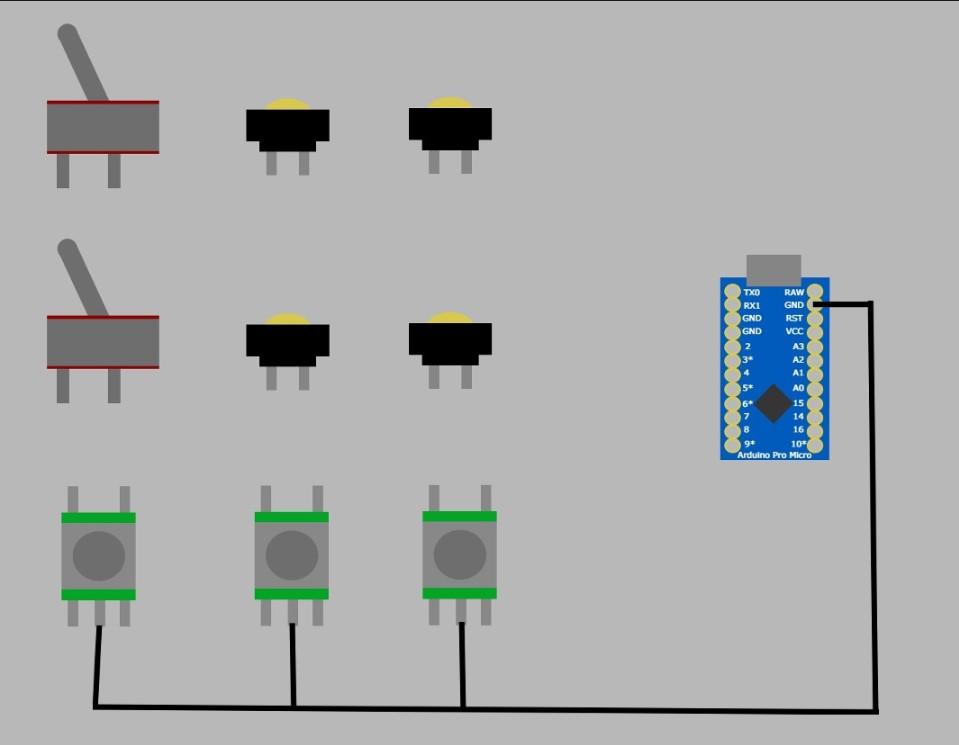
Button Matrix
In order to create your button box, you will likely need to create a button matrix. Essentially, the purpose of a button matrix is to save pins on your Arduino so you can have more buttons. If you are wondering how a button matrix works, its similar to how you would find cells in a spreadsheet: you would use the rows and columns to find the cell, for example, cell A4 would be located on row A, column 4. Something to keep in mind if you are using this simple button matrix is that if you want to use multiple buttons at the same time, you will likely encounter random button activation called "Ghosting" , this is why I wouldn't recommend latching buttons. If in your case you do not need as many buttons, you could also simply connect your buttons directly to the Arduino. If you want to do some more research on button you can refer to this article.
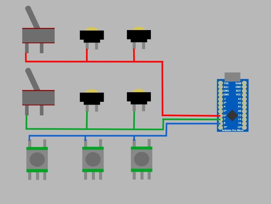
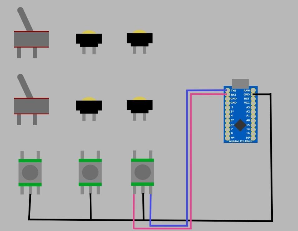
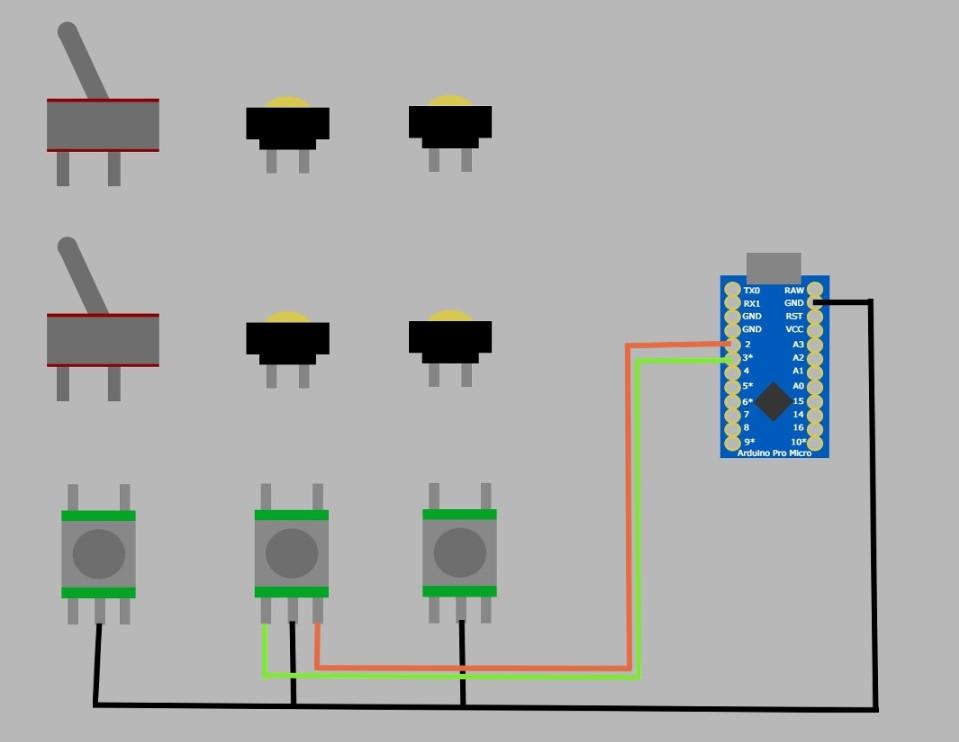
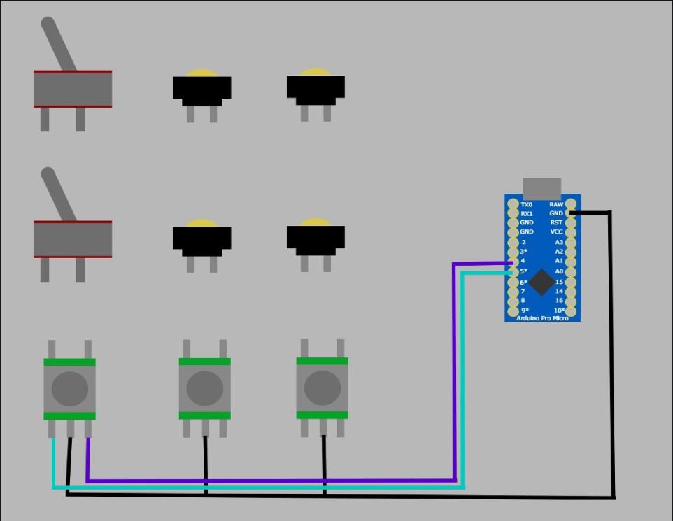
Rotary Encoders
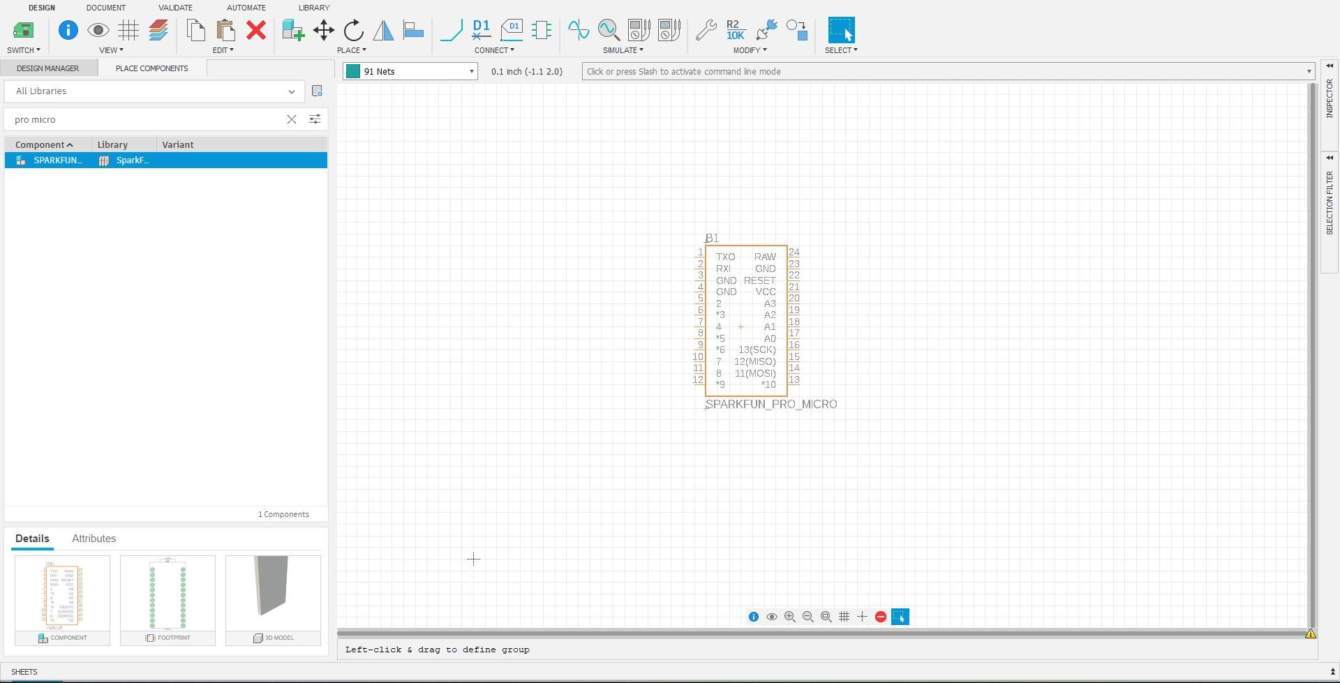
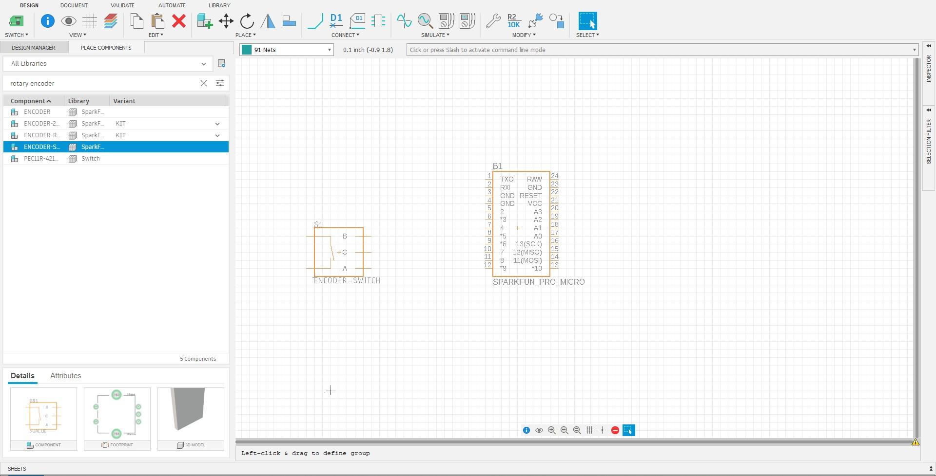
As for your rotary encoders, they must be connected individually to the Arduino, not through the button matrix. As you start to wire your rotary encoders (3 pins that relate to the rotary function, not the two pins that operate the push button) you MUST start wiring them from the first pin on the Arduino (TX0) and go from there sequentially. It is crucial that you start from pin 0 and go from there, additionally, it is important to wire your encoders as pairs, for example, you cannot wire your encoder at pins 4 and 6, they must be at 4 and 5. Wiring your encoders correctly is crucial to your encoders working properly so make sure to pay special attentions when creating your schematic and wiring.
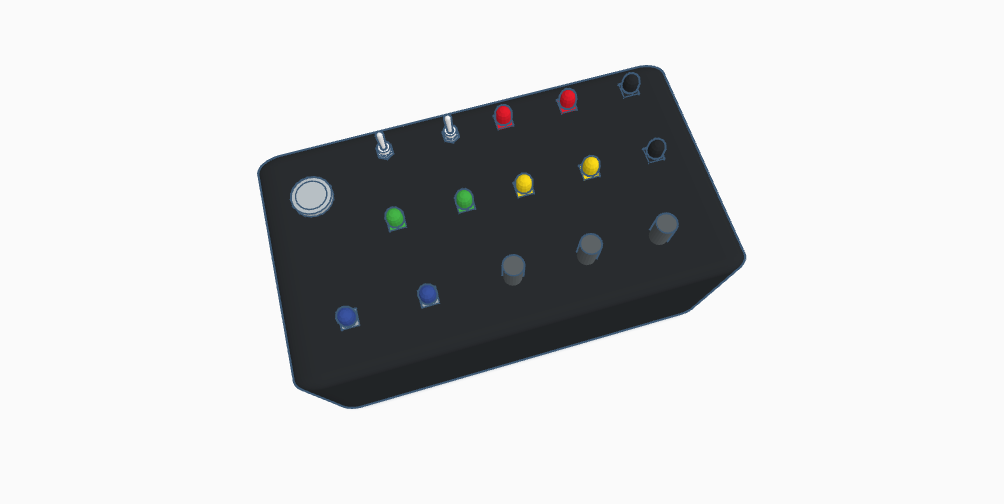
Creating Your Button Box Housing
.jpg)
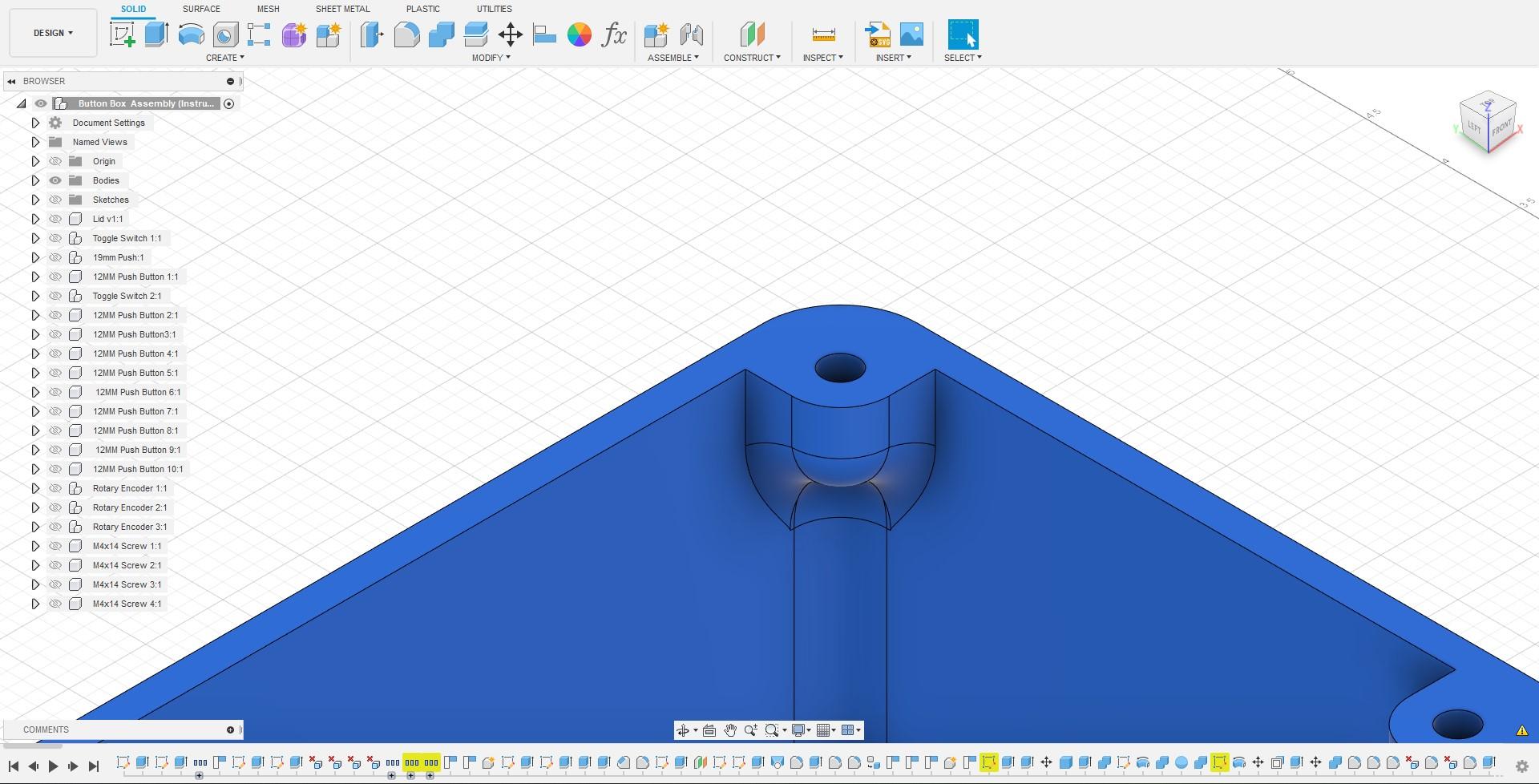
Creating Parameters
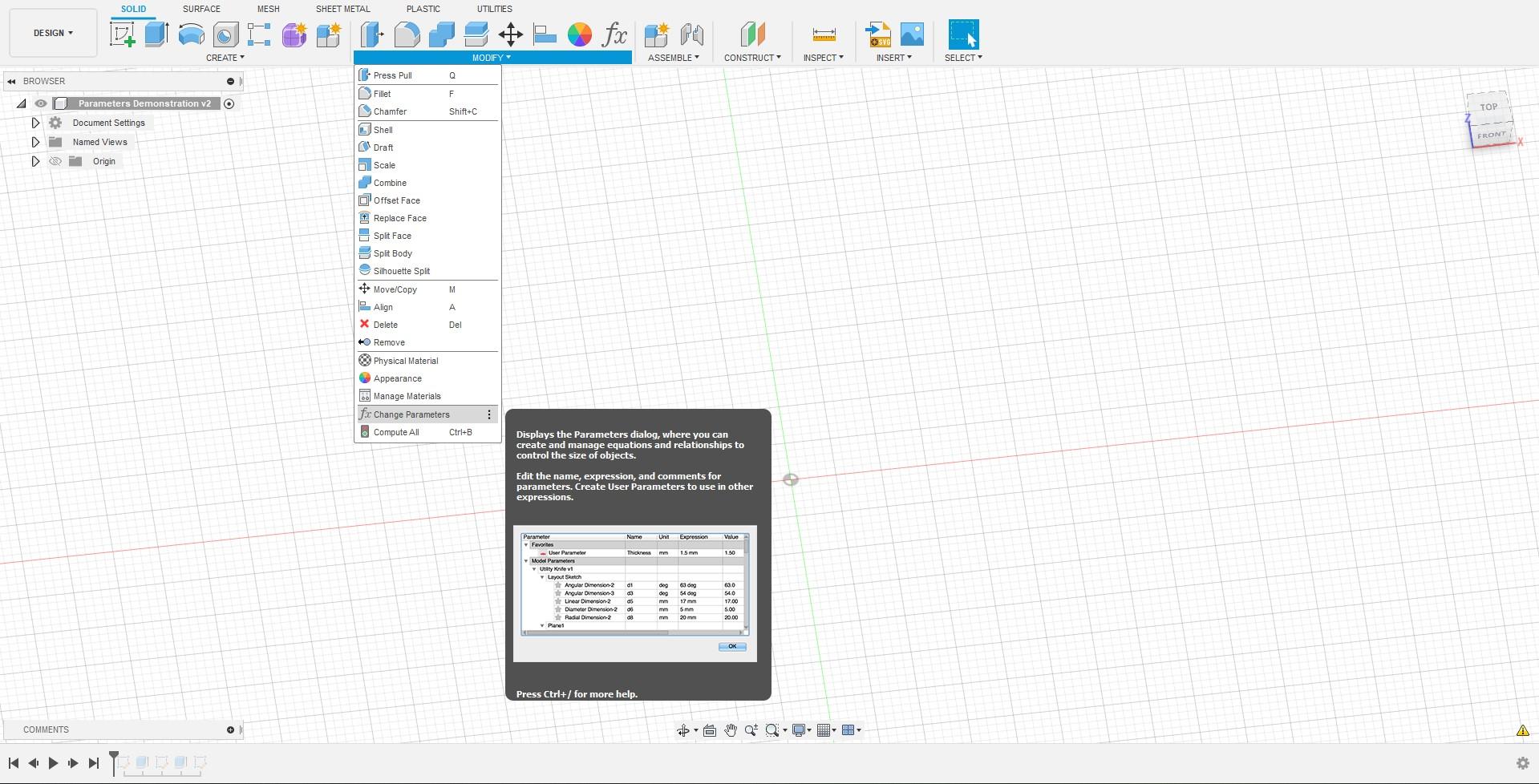
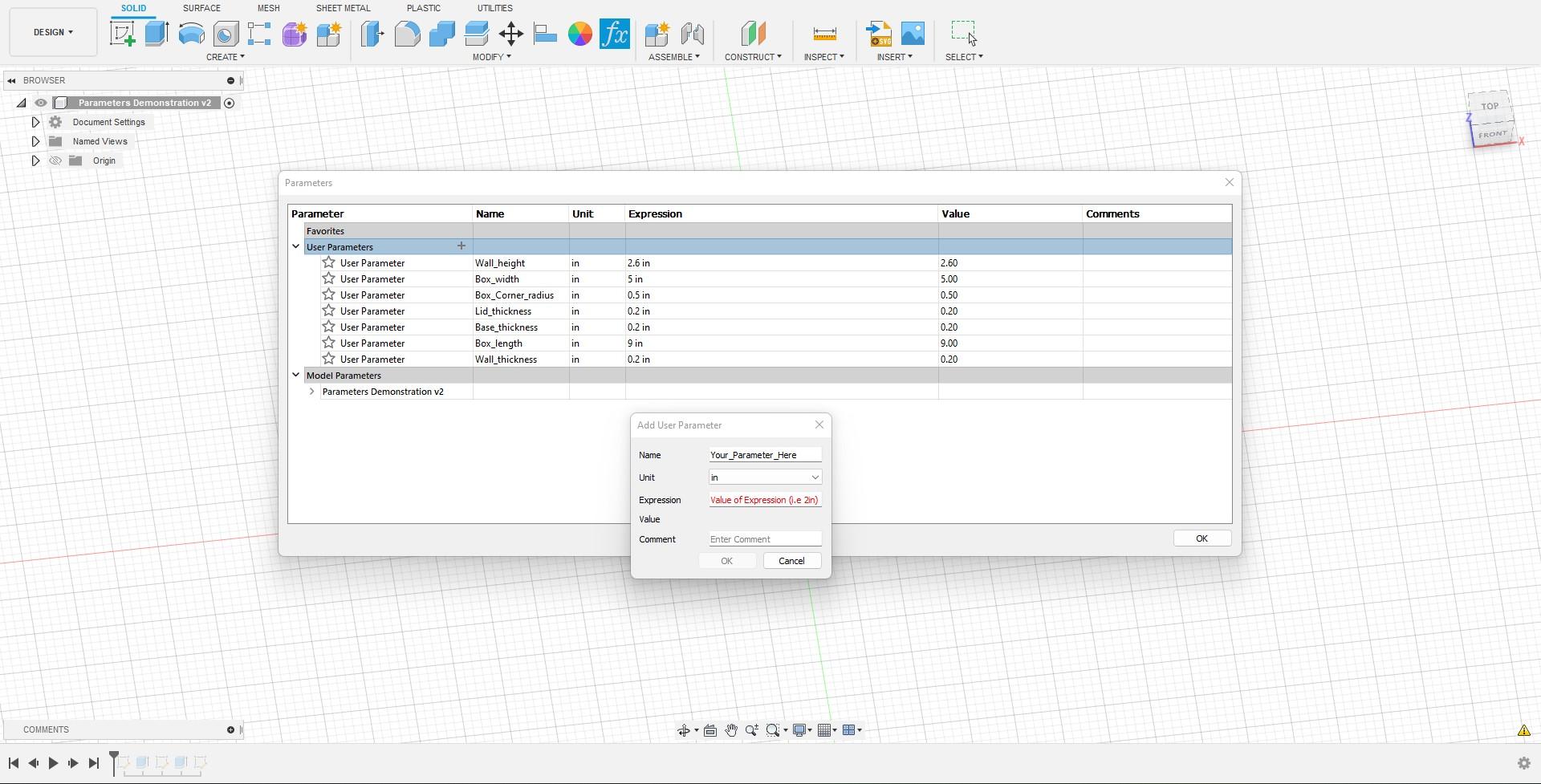
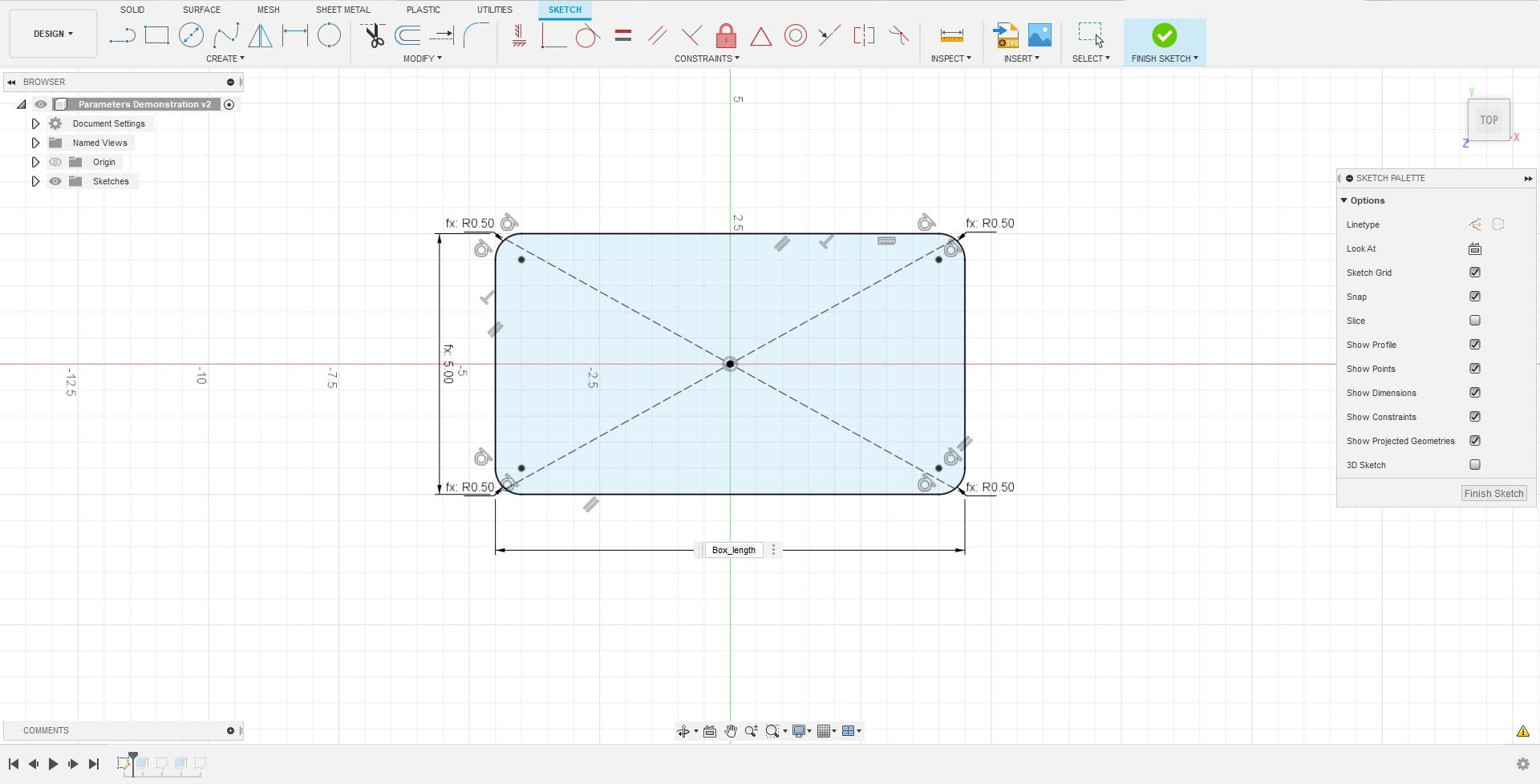
If you are new to CAD, you might not know about parameters, this was me a couple weeks ago. Parameters are essentially used to organize and store information about the object you want to create. Additionally, parameters allow you to make changes to specific details of your part later on in the design without errors. This ability is really useful when creating things like your button box where you might not be sure on the width or length of your button box and may want to change them later down the road. To access parameters simply go to the "Modify" dropdown in the Solids workspace. Once you click on the option, you can add parameters by clicking the "+" icon and editing. In this menu, you can choose a variety of values like different measuring systems (MM, Inches, Feet, etc.) and even different types of values (Degrees, Currency, Volume, Pressure, and more).
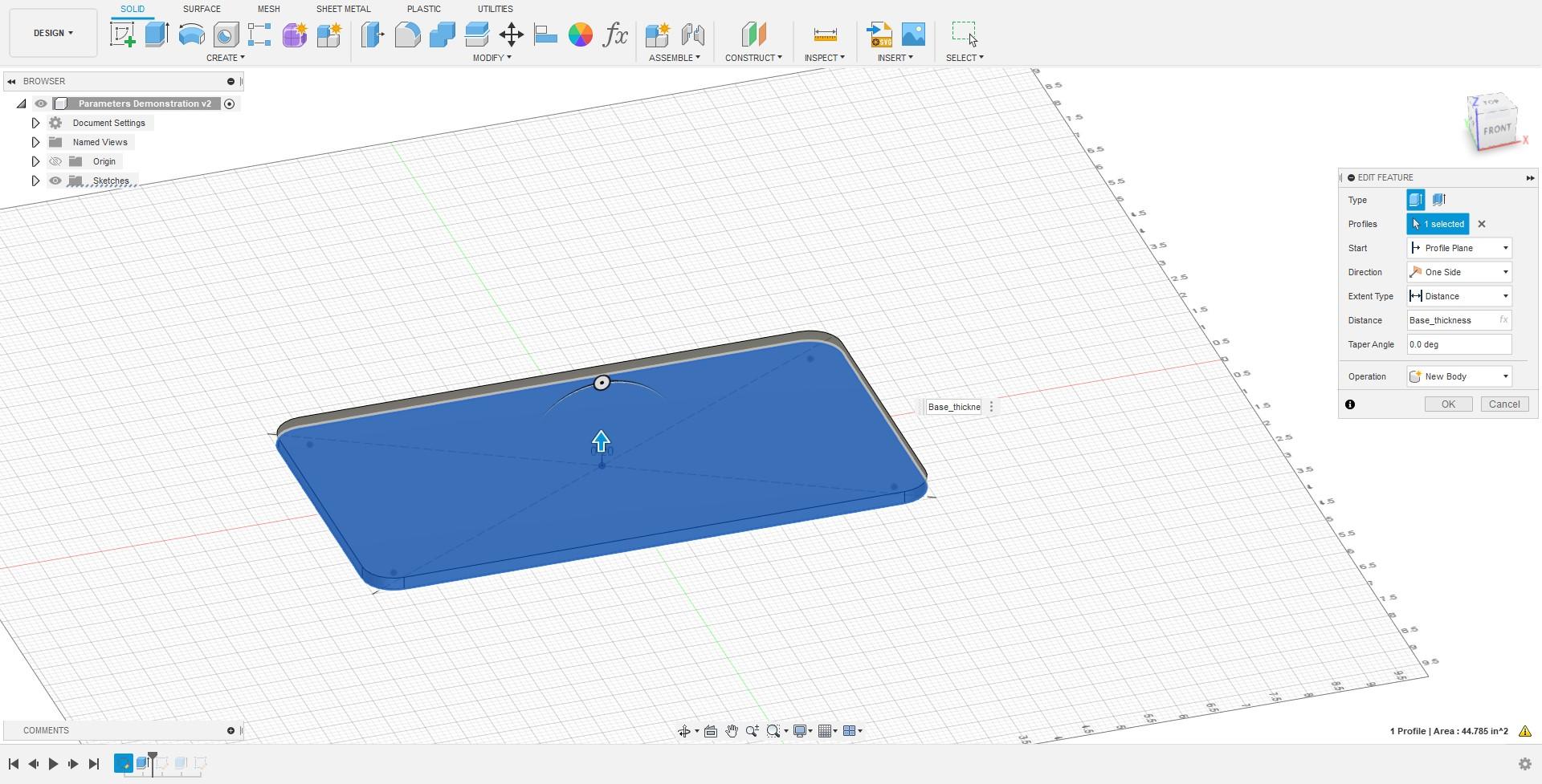
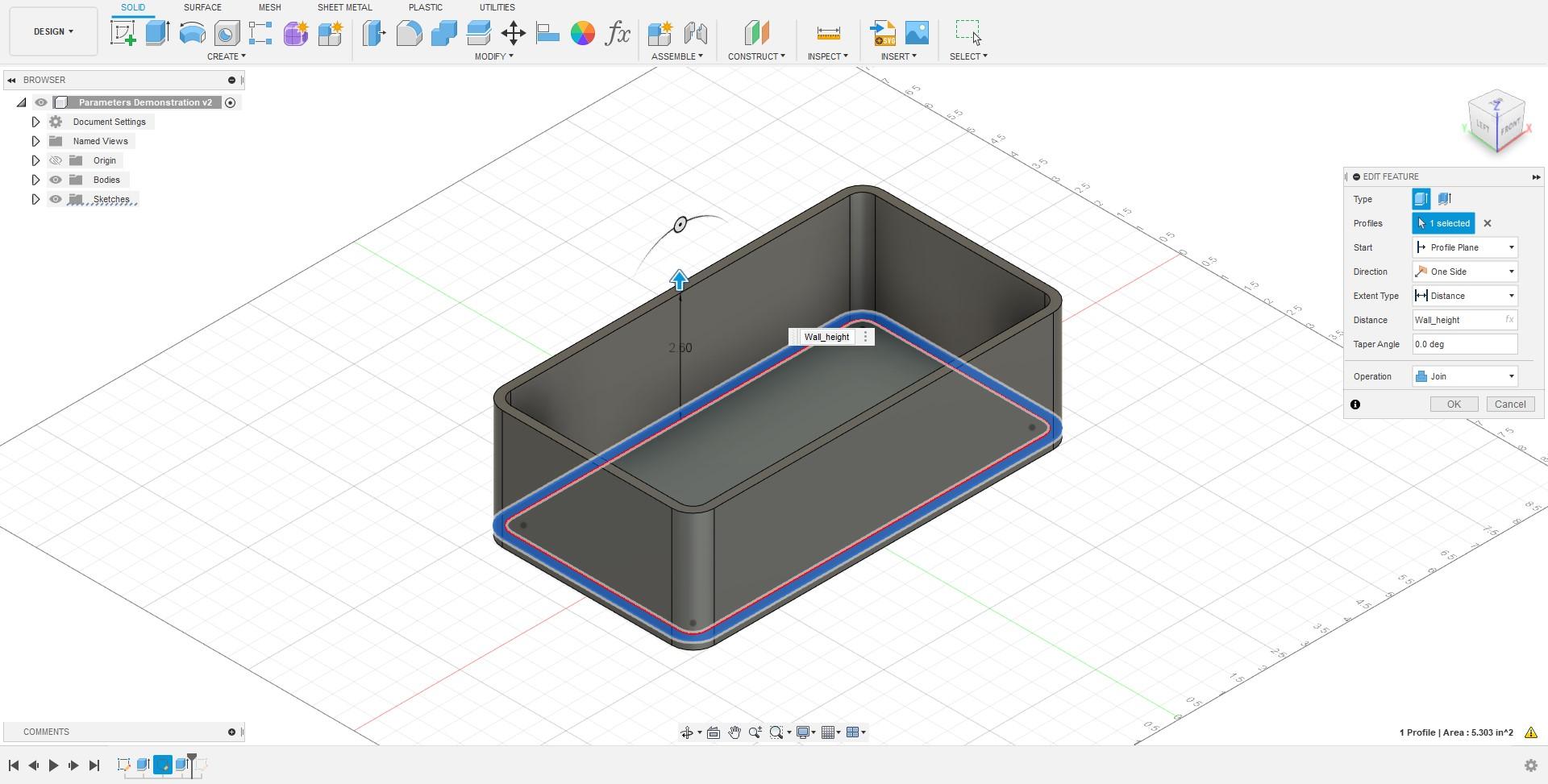
Using Parameters
To use parameters, you simply have to type the name of the parameter as if you were typing the value, for example, when you extrude, instead of typing the value you want to extrude by you would use the name of the parameter instead of the value.
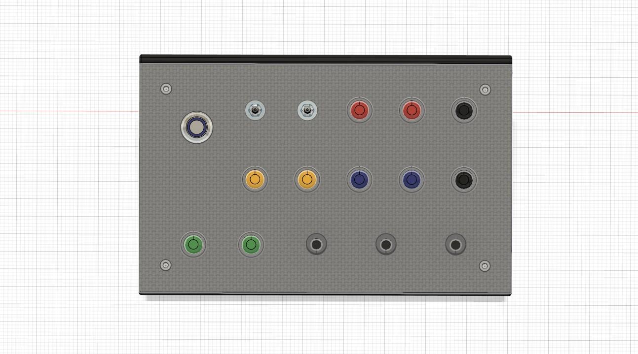
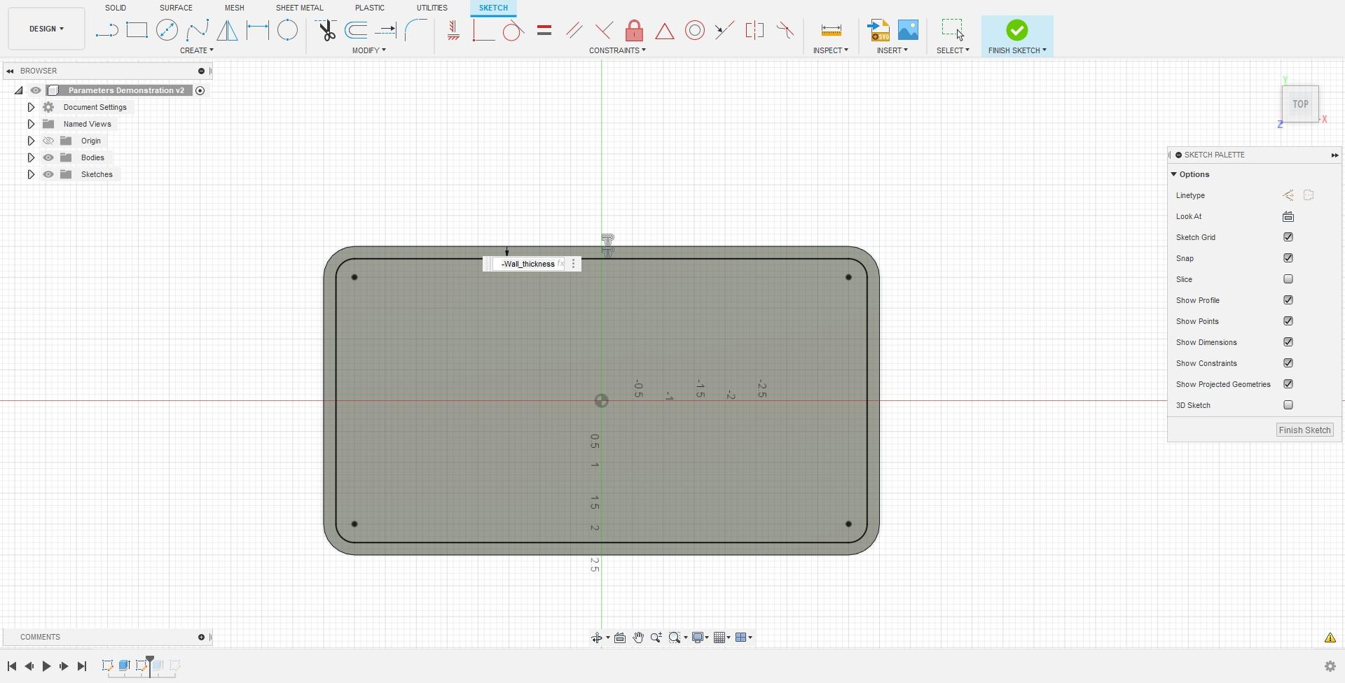
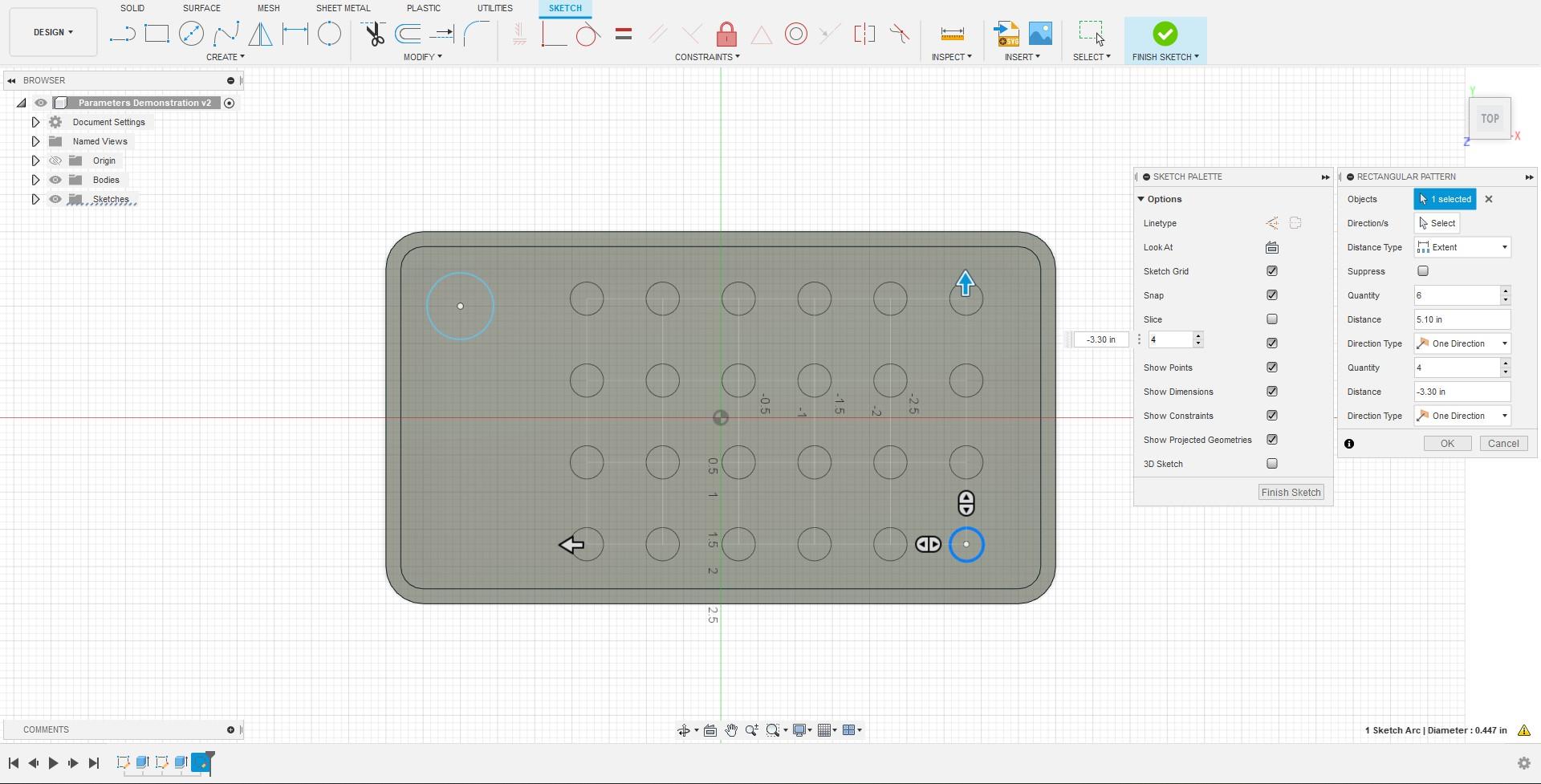
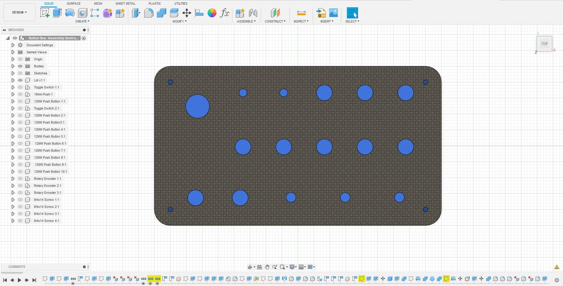
Creating your Lid
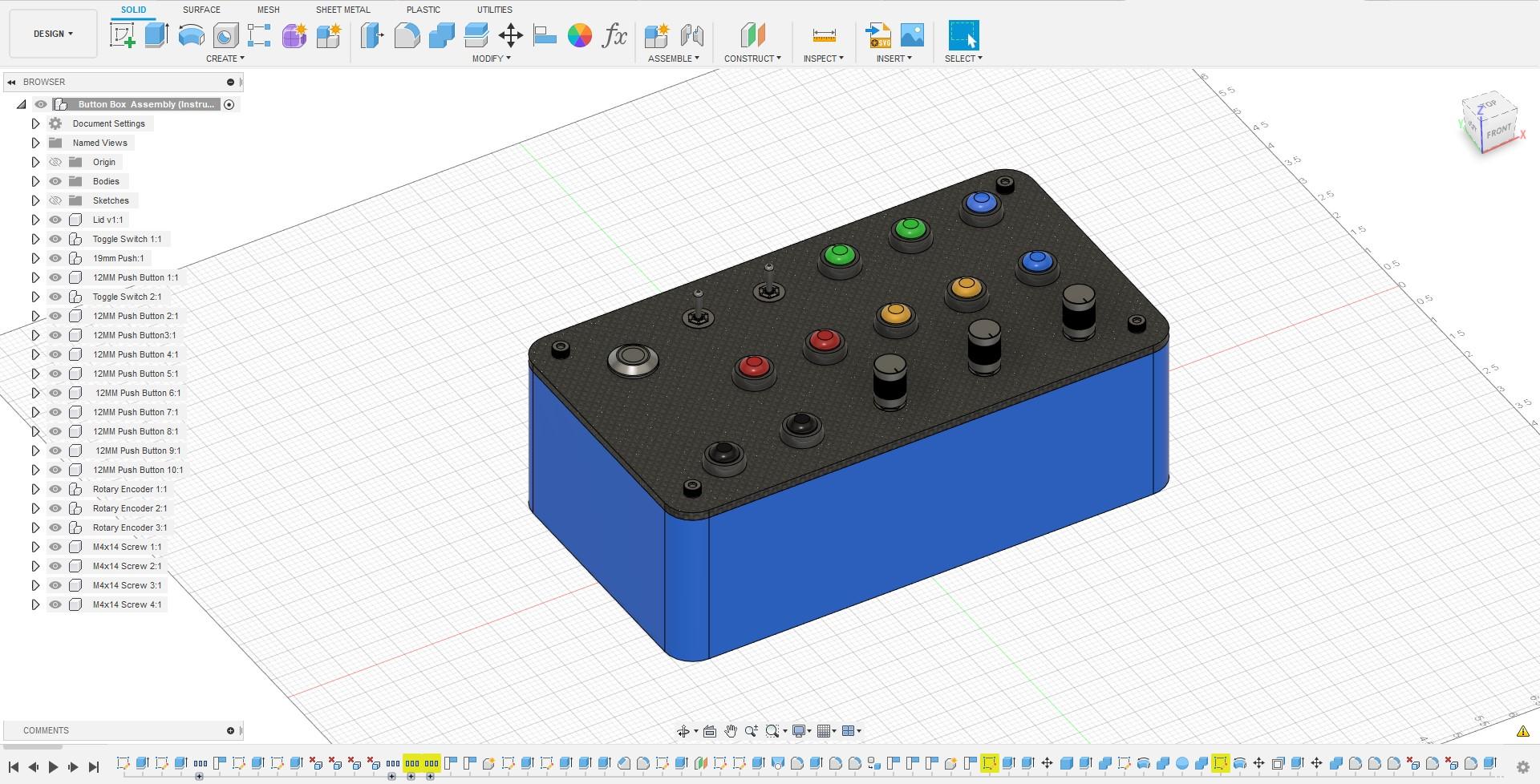
Now, this step will probably vary for most of you, but I have some tips to create a nice grid for your box and you can adjust it as you so please. A great tool to use when creating mounting holes for your buttons are the circular and rectangular pattern tools in the sketch workspace. The Circular Pattern Tool helps you create patters based on a center points, so this tool would be useful if you are trying to create a button box with a circular-type layout. Additionally, the Rectangular Pattern Tool helps you create a grid like pattern, this is the type of pattern I chose for my button box.
Creating a Schematic in Fusion360
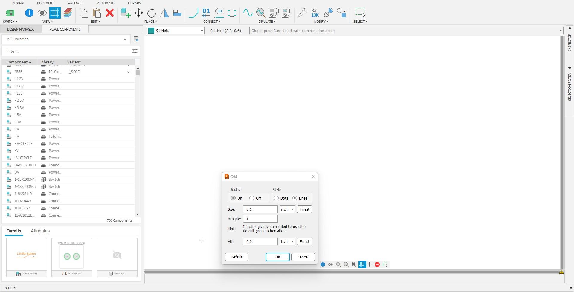

Enabling and customizing the Grid
The first thing I recommend you do whenever doing anything related to electronics in Fusion360 is enabling and editing the grid to your specifications. This is such a crucial step because when you make your designs you essentially base everything off the grid and getting the grid wrong would not be good when you finished your design. Another point to make is that it is SUPER IMPORTANT to NOT DEVIATE from the STANDARD INCREMENTS ON THE GRID, this is important because almost all default electronic libraries use the standard increments on the grid so deviating from those standards can cause a lot of problems.
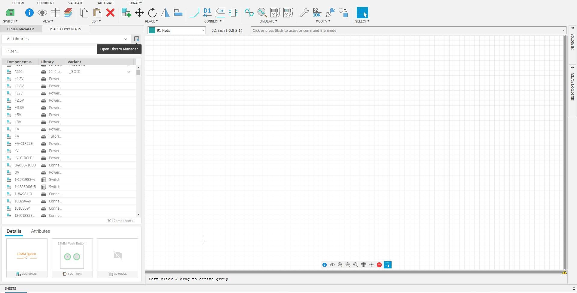
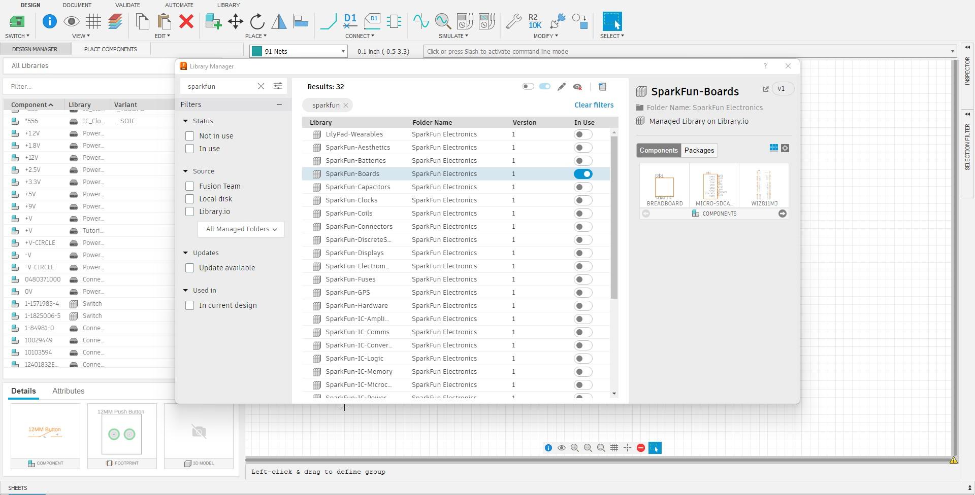
Adding 3rd Party Libraries
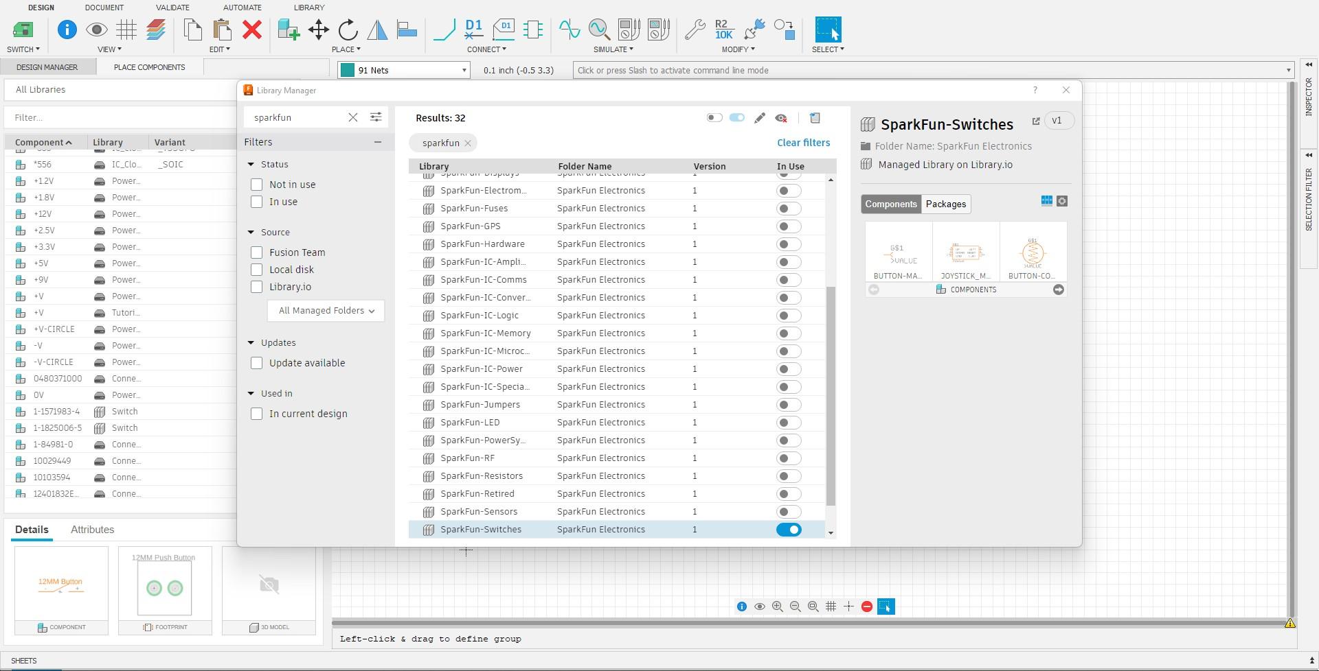
Another important skill to learn is how to add new libraries from manufactures or other third parties. As you can see on the video and pictures, the libraries button is to the right of the "All Libraries" drop down on the left side of your screen. After clicking this button, you are greeted with a pop-up window with various libraries. In this pop-up, you can search for libraries "SparkFun-Boards" and "SparkFun-Switches" which are the libraries I have used in my design. SparkFun libraries are great for hobbyists because of their common electronics, you can also search for parts for your button box from them as they are a great resource: SparkFun Website.
Creating Your Own Electronic Library
Sometimes you may not be able to find a library that suites your needs, so in that case you can create your own library. In this cases, it is best to have a manufacture's data-sheet of your part so you can accurately design your electrical component, but you could also simply measure the part yourself with a caliper.
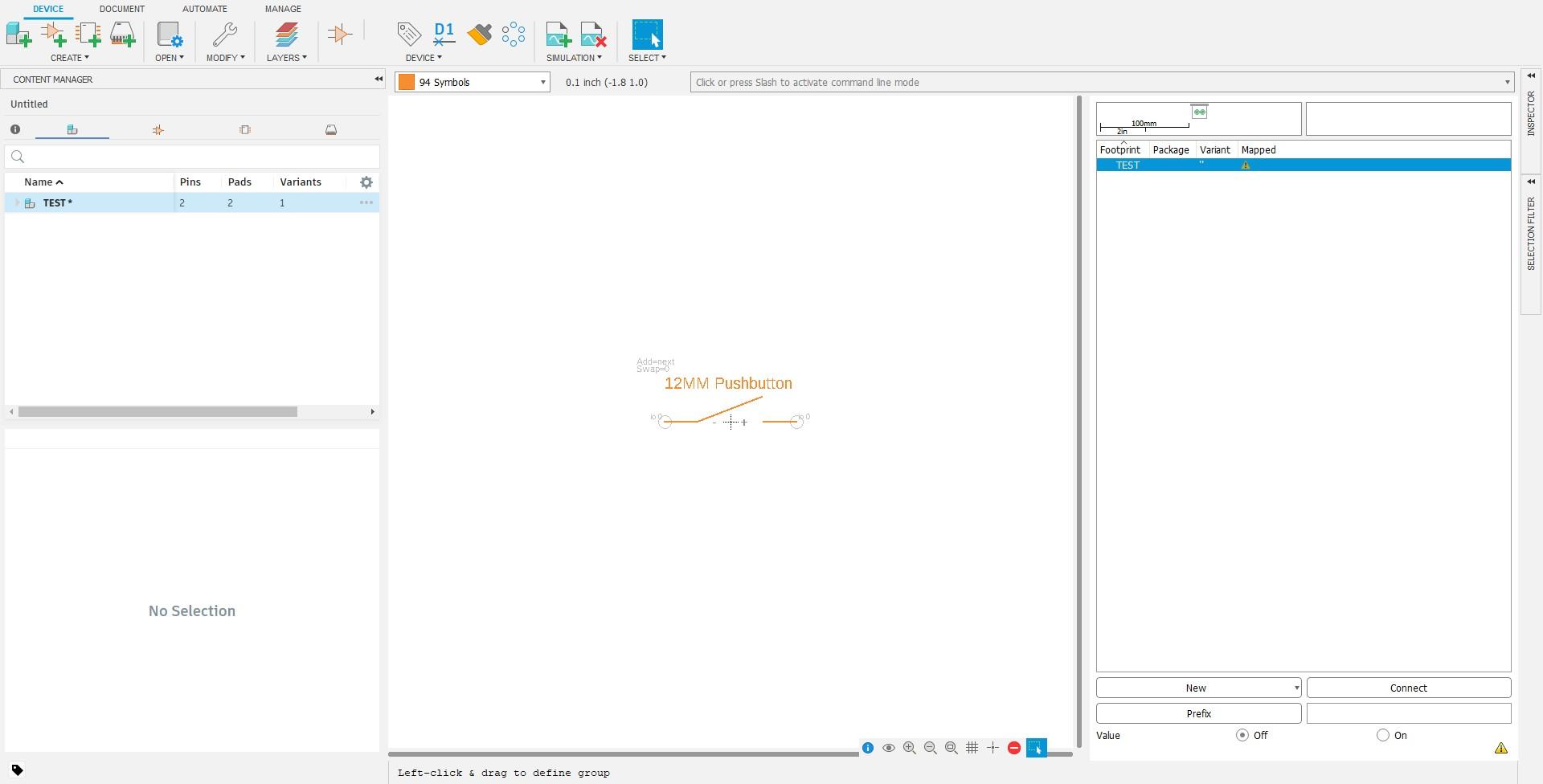
Creating a Symbol
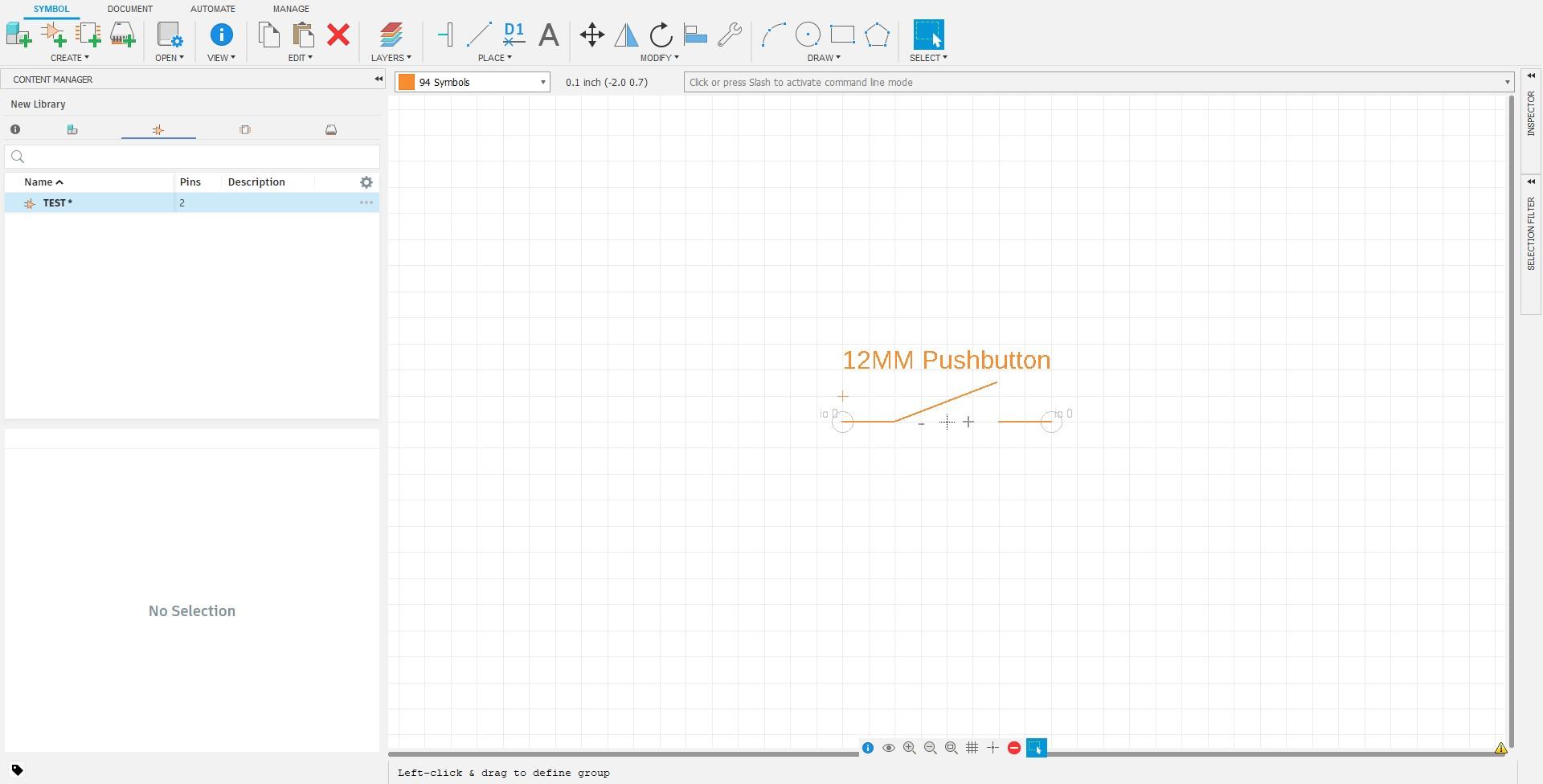
To start creating your own electronics library, you must start by creating a symbol. A symbol is essentially a diagram of your part's function, the symbol's only real purpose is to mimic your part while creating your schematic in Fusion360. With this in mind, your symbol does not have to be dimensionally accurate, it only has to represent your part. So, as an example, I will be creating a 12MM Push Button in this tutorial. To start I added 2 Pins, the positive and negative pins on my button. To represent a switch in the schematic, I also added a diagonal line. After creating your pins I recommend you name them, I named mine "+" and "-". After that, I also added "12MM Pushbutton" to easily identify the device when creating my schematic.
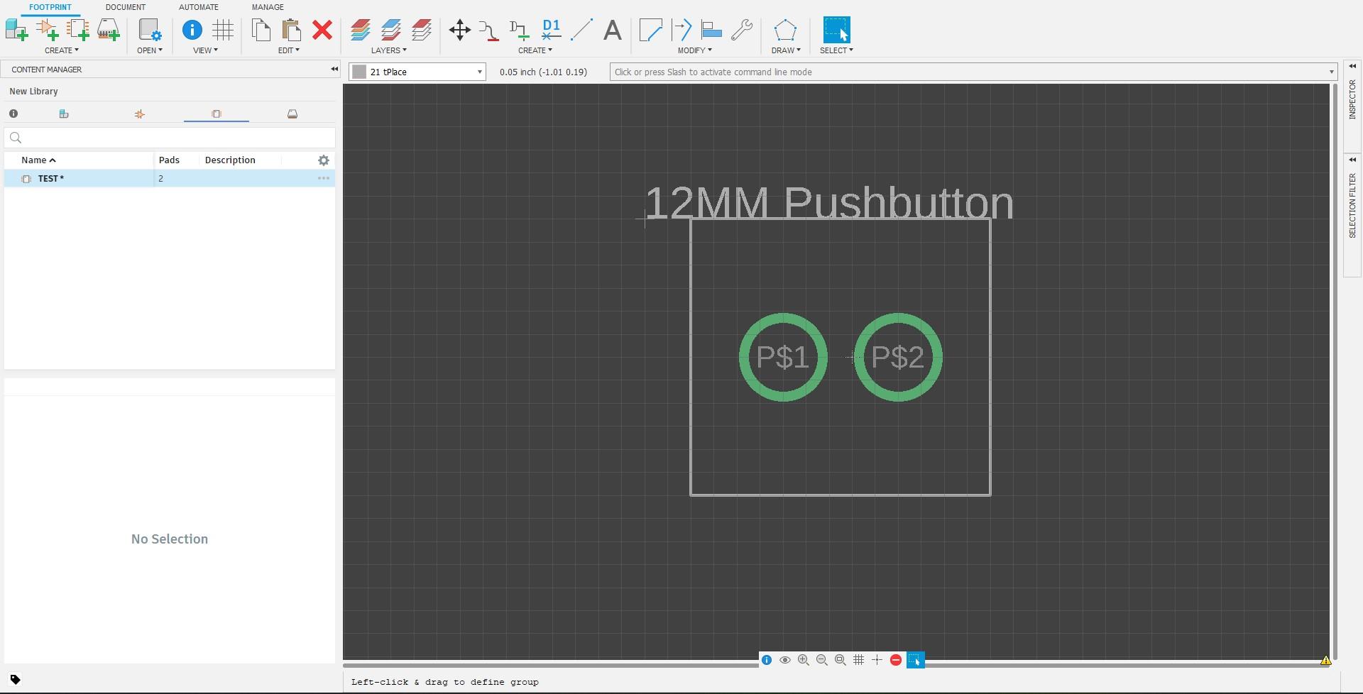
Creating a Footprint
Now, we need to create the footprint. The footprint is the part of your device that will actually appear on the PCB and should be dimensionally accurate. Now this next step will depend on how your part mounts to the PCB: Surface Mount Pads or Through Hole Pins. In my case, my push button has through hole pins so I will use through hole pins on my footprint, but your part may have surface mount pins so if yours does make sure to use them. Once selected, edit your mounting type to fit your part in my case, my pins are .15" in diameter so I edited my through hole pins accordingly. Once edited, make sure to use the coordinates in the top bar to place your mounting fixture correctly. If the grid is to big to place your mounting fixture correctly, press the "Alt" key to go into smaller increments (this does not affect your grid's size so do not worry about the warning I gave earlier).
Creating a Package
This step is not necessary if you do not feel comfortable in modeling, but can be useful if you want to see your PCB in 3D. In this step all you need to do is create your part in CAD, you could use the presets on the right, but I find that they are mostly for ICs and other small chips, not really for buttons. So if the presets don't suite you or you've already designed your part you can go into the "Solids" workspace to design or import your part.
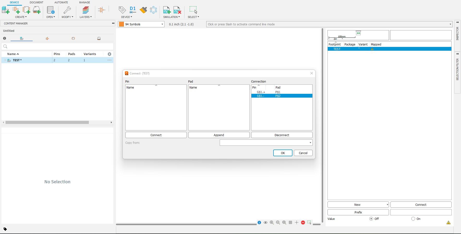
Creating a Device
If you want your part to work you MUST perform this steps as this groups everything you did above into one device. So to create your device you have to add the symbol you made previously, and then add your local package. After adding both, you must connect them by connecting the pins, this is why it is important to name your pins. After doing so you can save your electronics design and it will appear in your libraries, already installed.
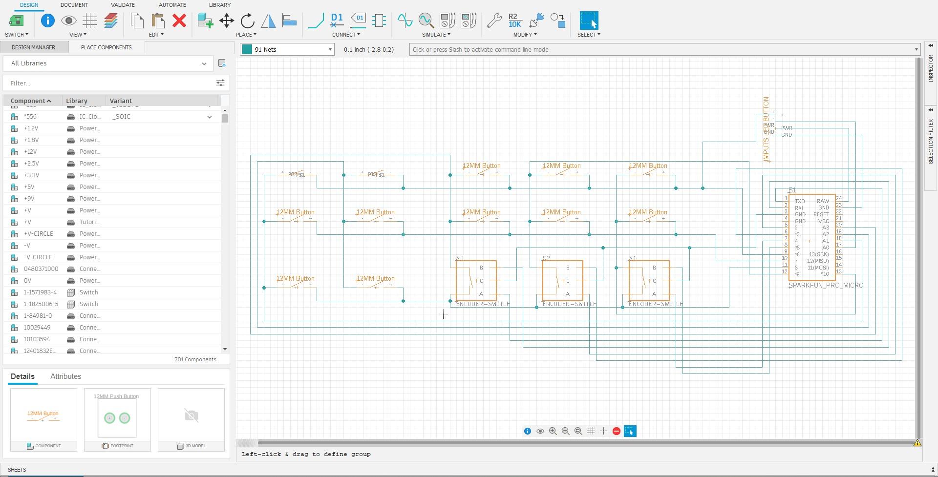
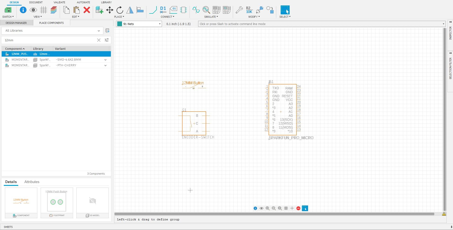
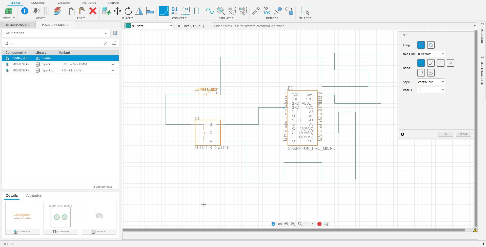
Creating Nets
Now that you have all your electrical components in your design file, you can start creating nets which are your wires. This is where making your schematic before-hand is helpful as there is fewer confusion. If you want to interconnect nets make sure to use junctions which should appear as a dark-blue dot in the middle of the cross-section of your nets. Once completed you can move on to pushing your schematic to a PCB.
Pushing Schematic to PCB

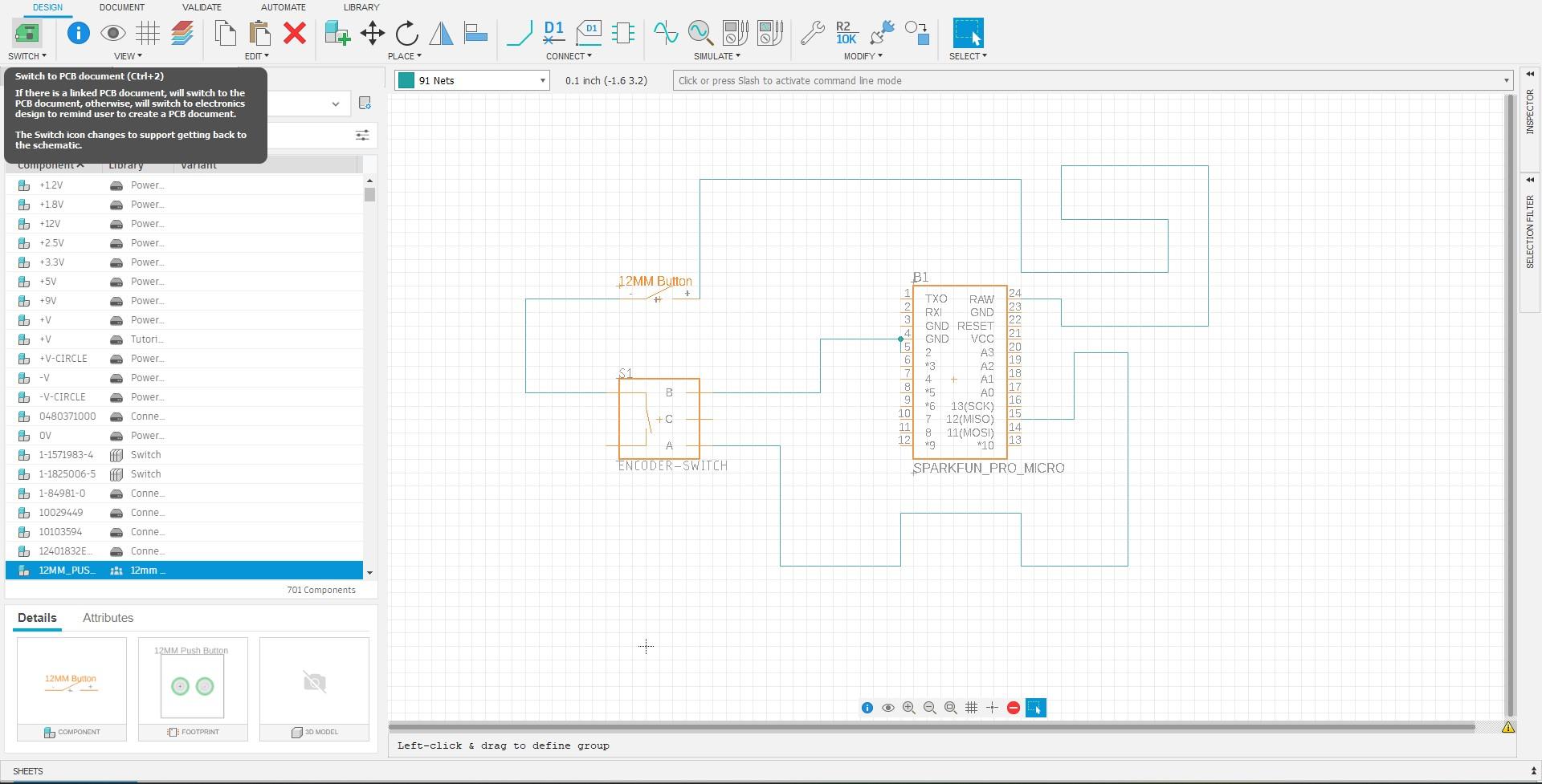
Changing Workspaces
To begin creating your PCB, start by changing workspaces. This can be done by pressing the button in the left-hand corner while in your schematic file. After changing your workspace, do not forget to enable and customize your grid to the specifications you need.
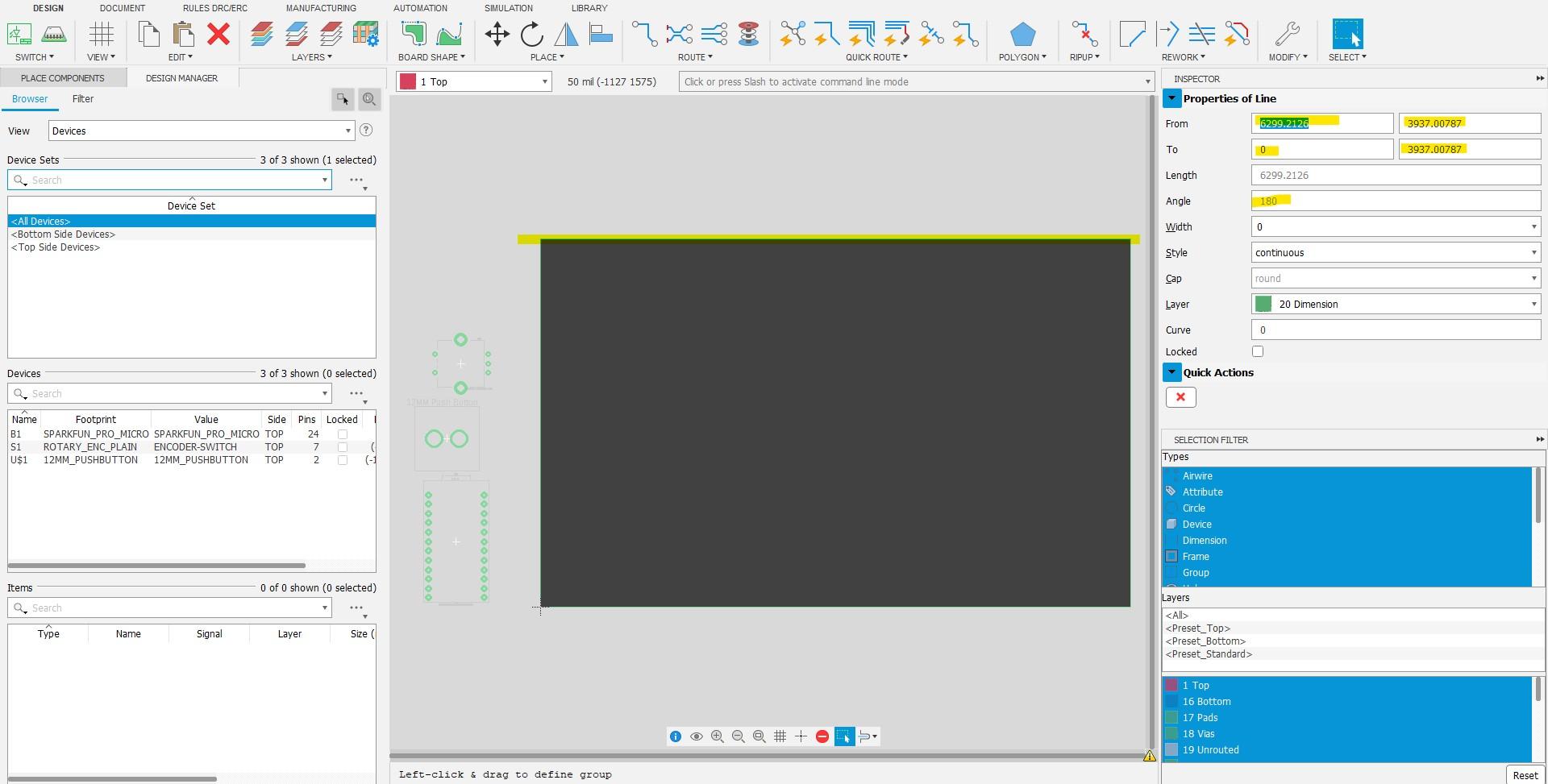
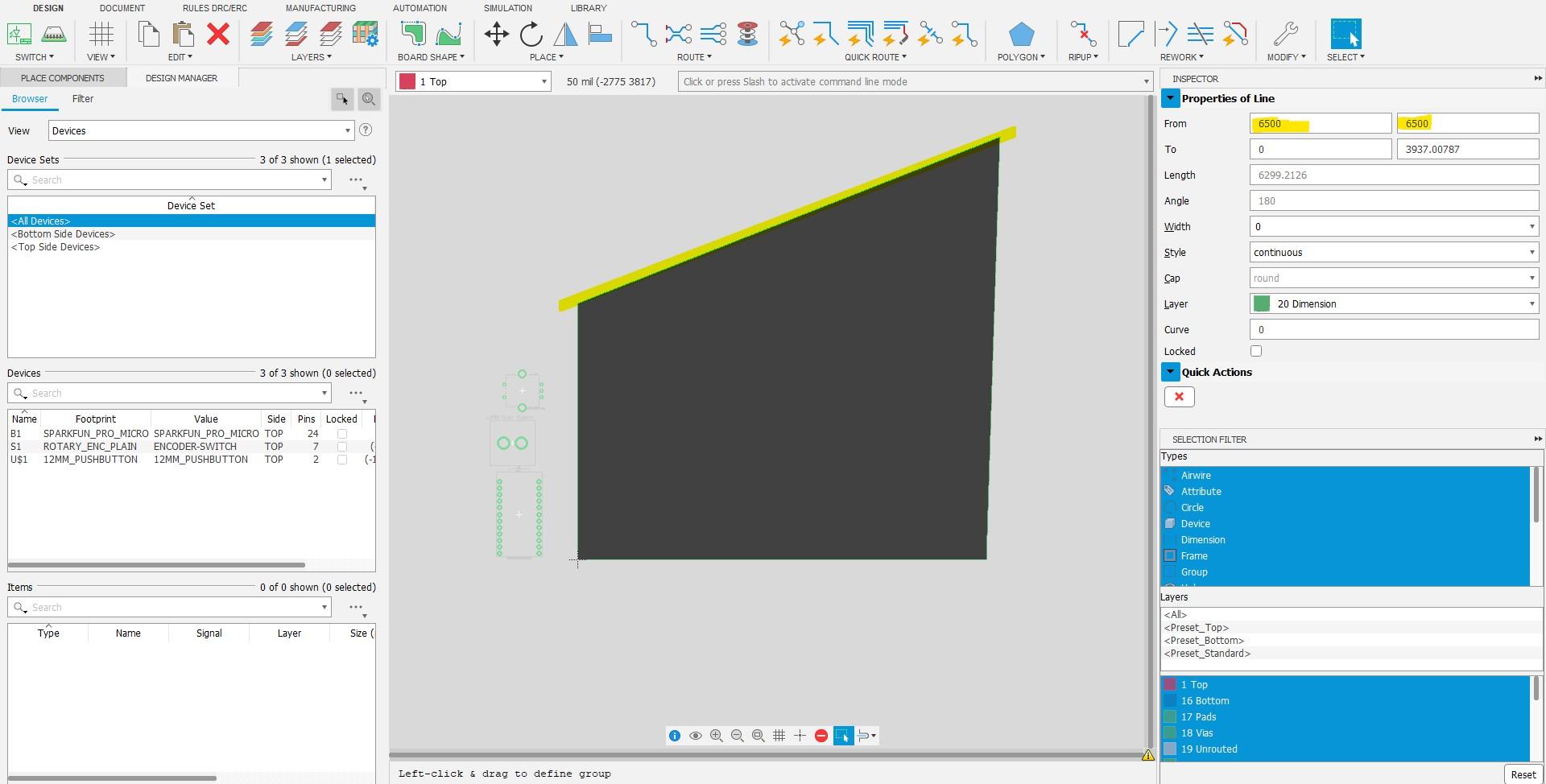
Changing PCB Board Dimensions
To change your PCB board's dimensions, simply left-click on one of the border lines and make sure you have the "Inspector" side panel on the right side enabled. In this panel you will find the line segment's endpoint coordinates. You can change these coordinates to fit your lid. Make sure that you have changed the units of your grid as the coordinates will differ if you have incorrect units selected.
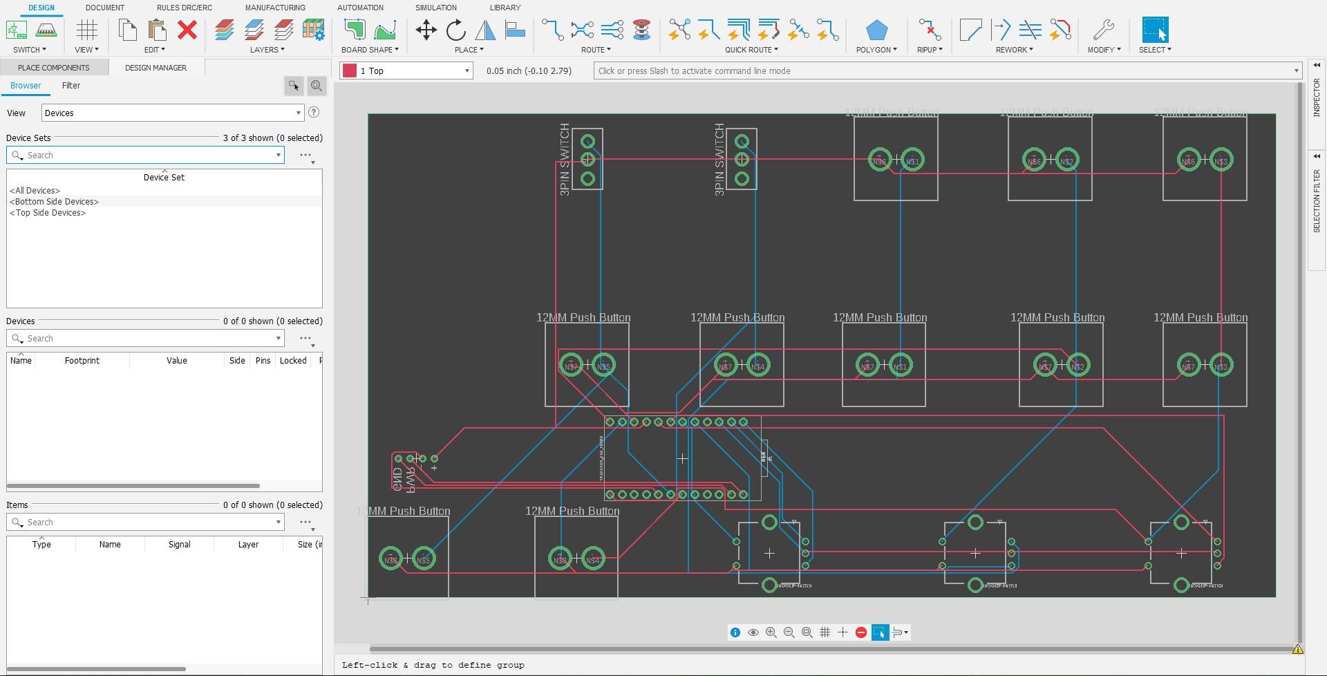
Moving Components
To move components, click on the origin of each component and move them around as you so please. I recommend you use the coordinates of the origin to correctly line up your components relative to the mounting holes in your Button Box Housing. You will also notice that white lines appear as you move your components, these are the nets you created earlier. These lines will help you route your nets if you choose to route them manually.
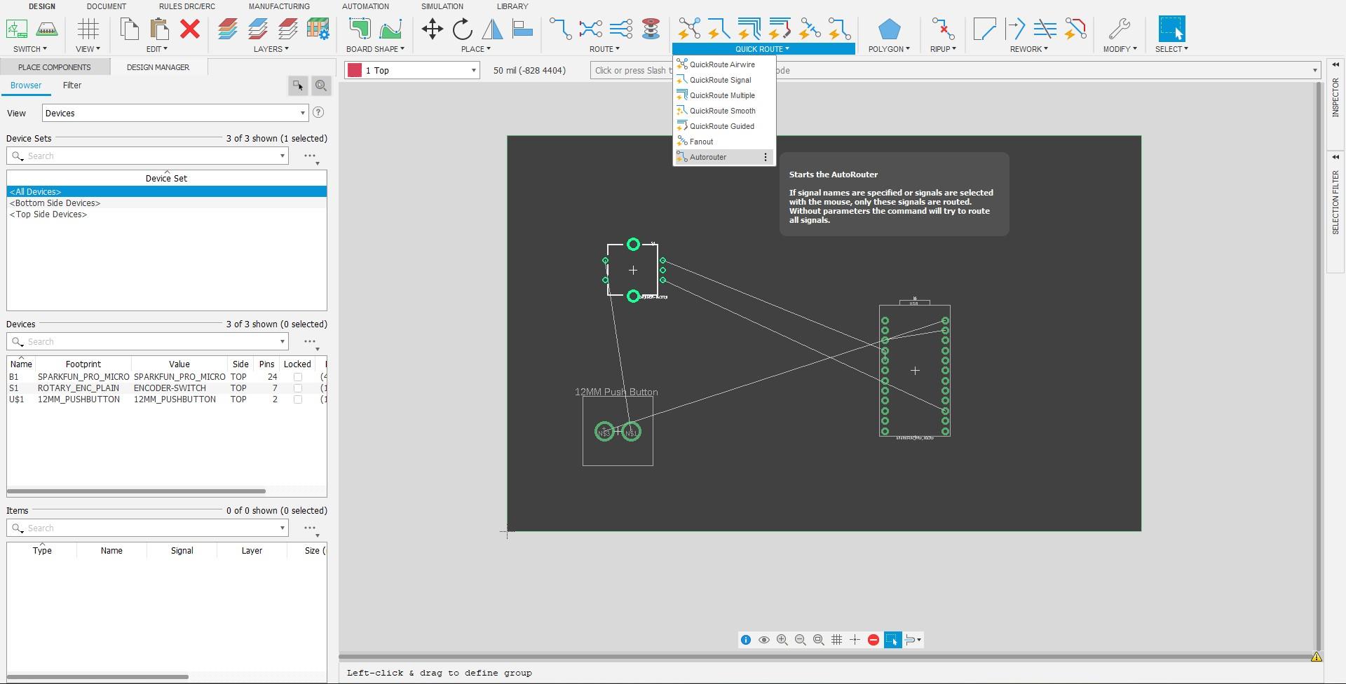
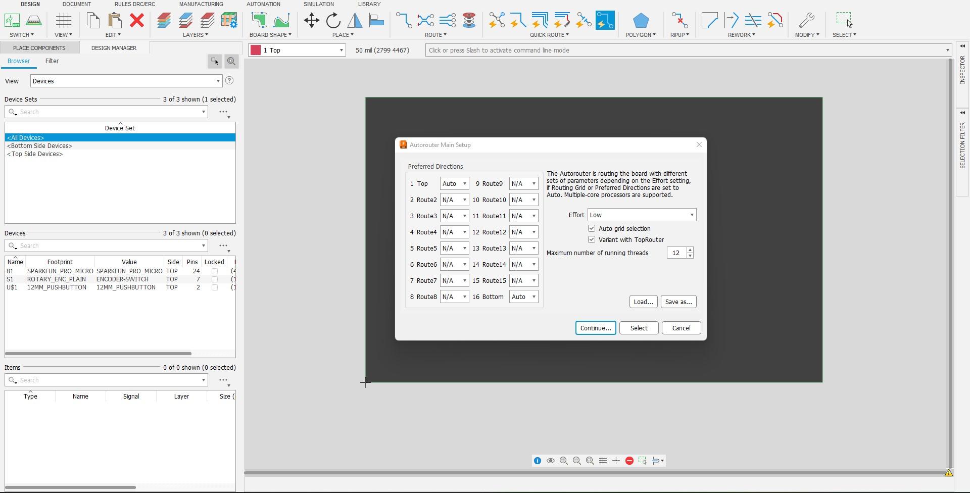
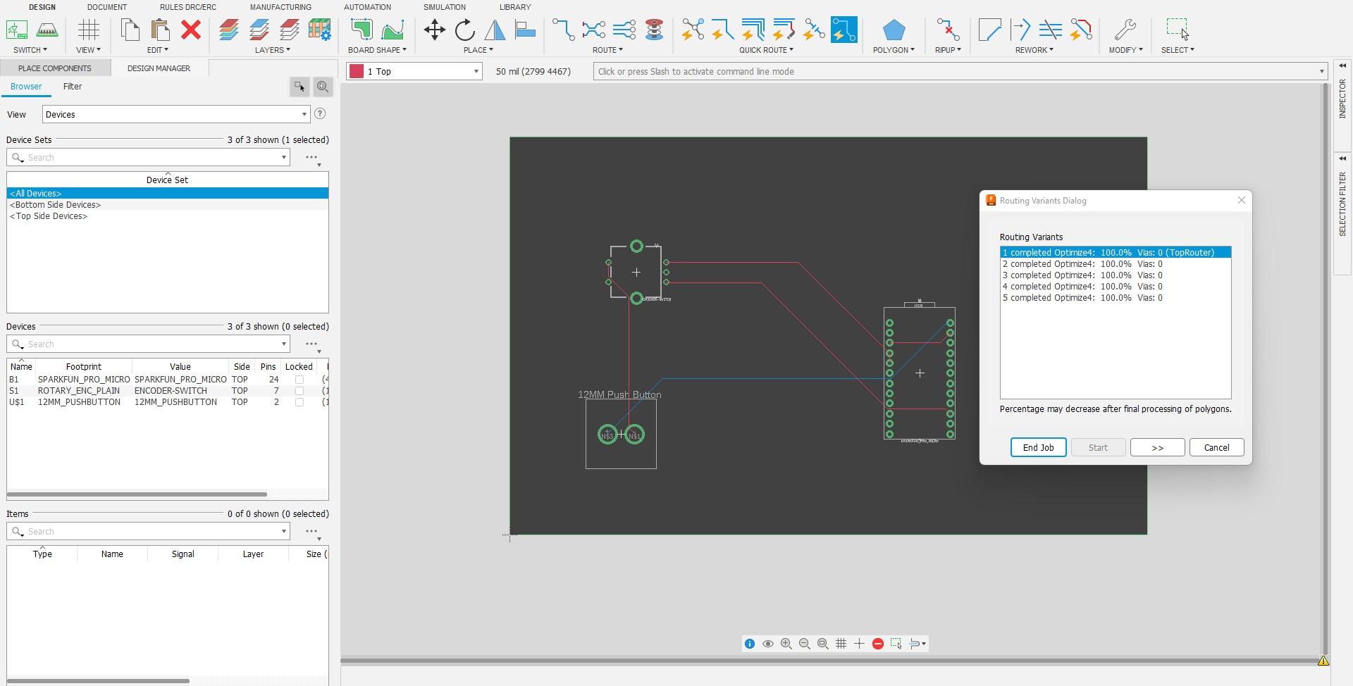
Auto Routing Nets
The best way to route your nets is using Fusion360's Auto Routing tool which uses AI to automatically route your nets. You can determine which result you want from the algorithm from the options provided. I recommend that you choose the option with the least amount of vias as this will save you money if you decide to make your PCB through a manufacturer.
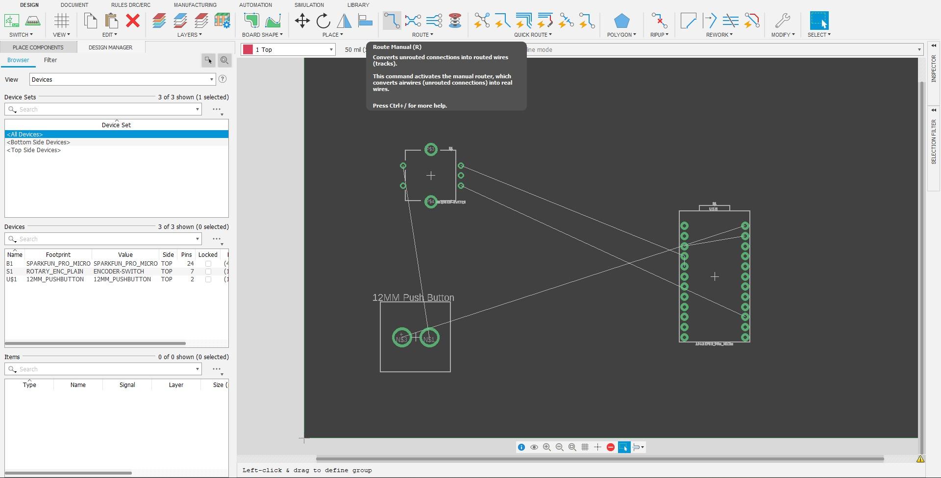
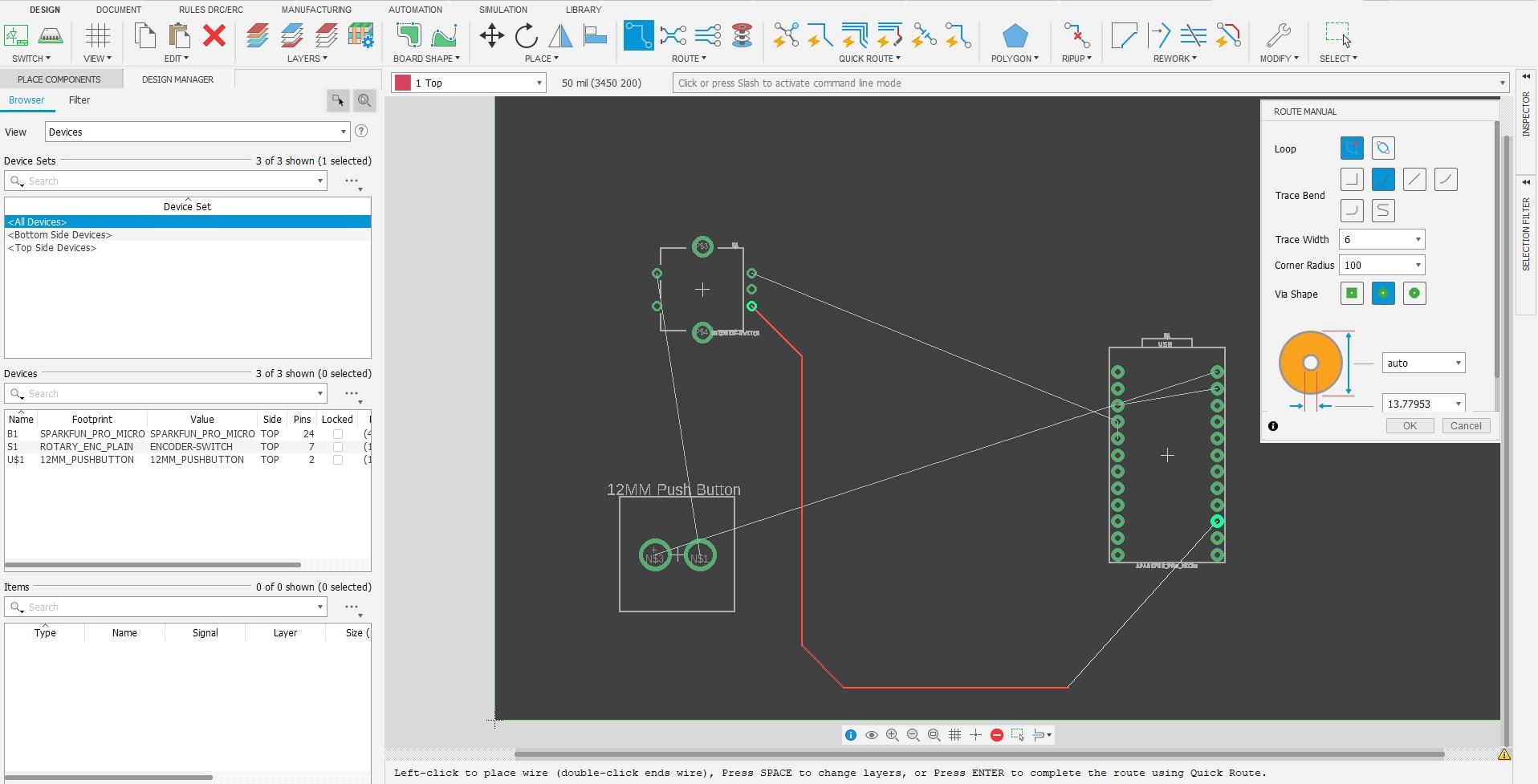
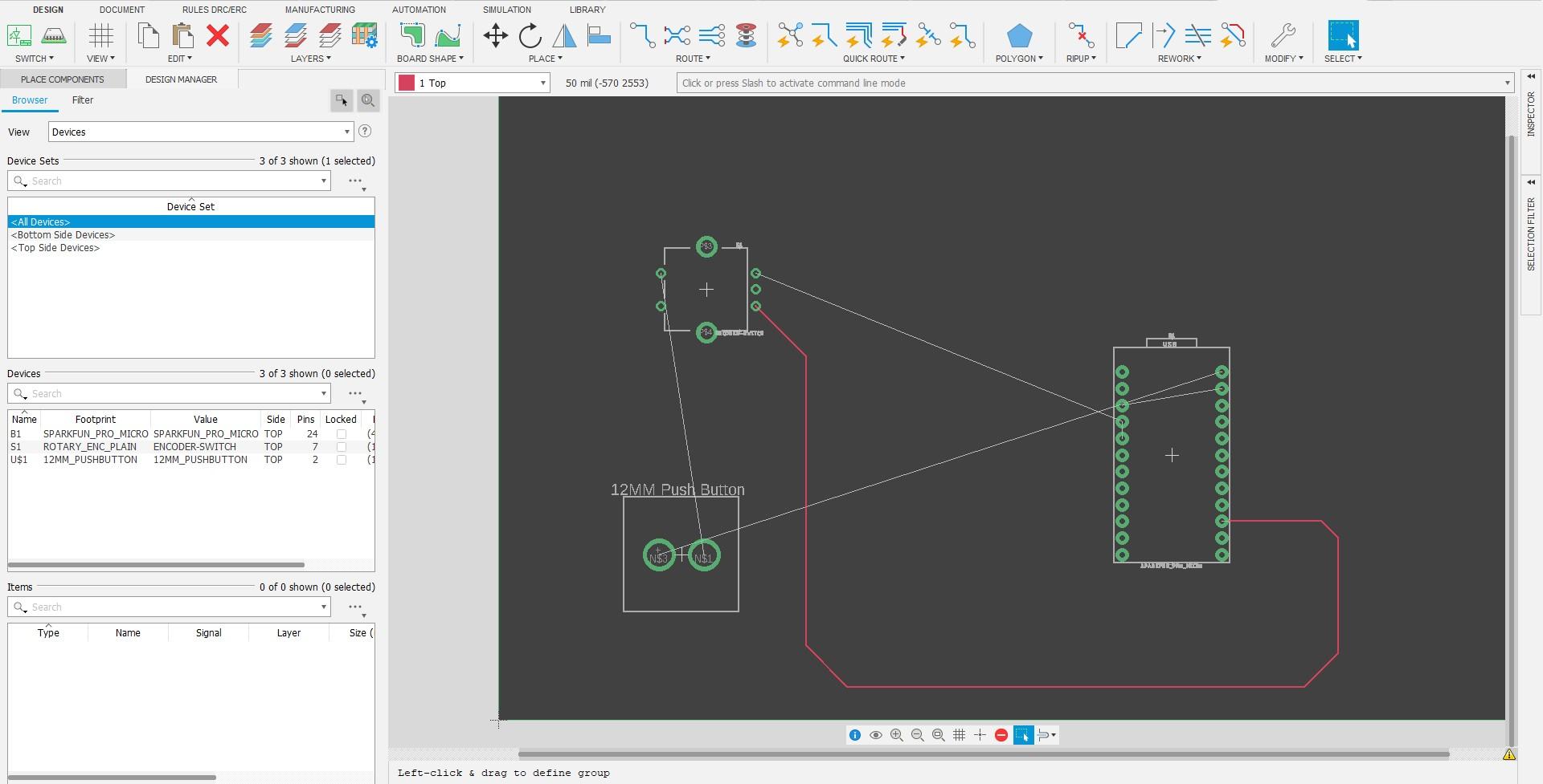
Manually Routing Nets
You also have the option of manually routing nets. To route nets simply select the "Route Manual" tool and route the nets the same as you would with a schematic. You can use the white lines as mentioned before to correctly route your nets. Additionally, you can add vias if you need them with the given option.
Wiring
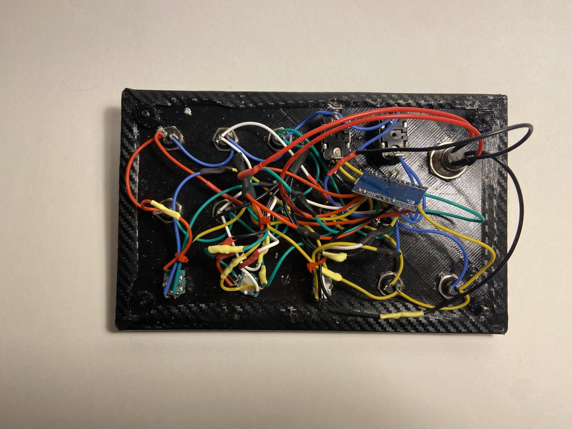
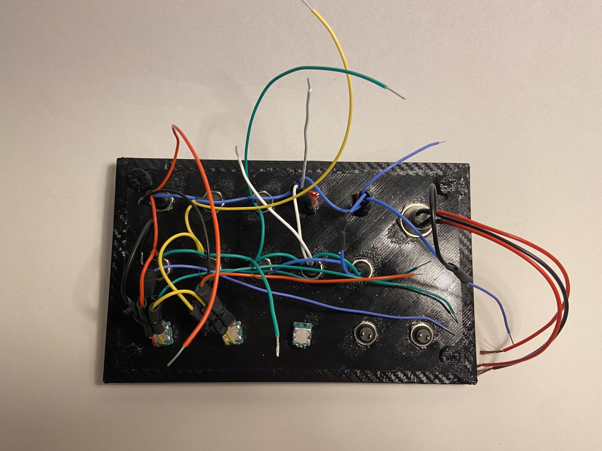
Wiring / Soldering to PCB
I decided not to make a full video tutorial because it would probably be pretty boring and soldering is pretty straight-forward. Even though soldering wires or to PCB's can seem straight-forward, I still ca give you some tips to reduce risk and improve your build as a whole. Again, I am by NO MEANS a professional, so please get advice on how to not burn yourself or other things around you while soldering from professional resources.
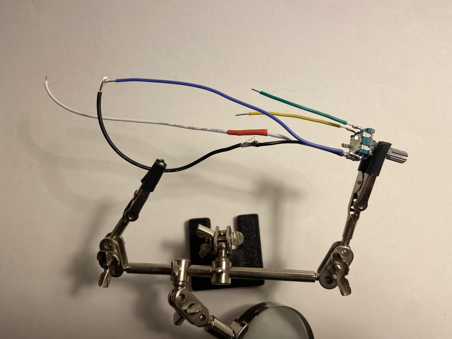
Tips
My first tip while soldering is to make sure that you've finalized your schematic and are keeping it close by to double check your wiring as you do not want your project going wrong, or even worse, damaging something. Another great thing to keep handy are these great tools called "Helping hands" which are the little clamps that hold electronics on the thirds picture. These are great when you need to solder little wires to electronics while soldering. Another thing to use are zip-ties to keep your wires tidy, this will make debugging easier if it comes to that point. Lastly, its a good idea to use a fire resistant soldering mat that you can work on safely, along with a fan or something to blow the air around you as the fumes produced by the solder can be irritating and harmful.
Resources and Additional Info

Hopefully I've helped you learn something new with this tutorial I made. I had the motivation to create this tutorial because of the frustration that I've experience in learning, so I decided to help you guys out and maybe help relieve some of your frustration. These are some great resources that have helped me out tremendously, so I've made a short list of some great resources that you may find useful.
Product Design Online - Fusion360 Tutorials Website Youtube
Autodesk Forum - All things CAD Website
Fusion360 Youtube - Fusion360 Tutorials Youtube
AMSTUDIO - Sim Racing Tools Tutorials Youtube
Wim - Button Box Tutorials Youtube
Pixlr - Free Layered Photo Editor (For Schematic) Website
Arduino Forum - All Things Electrical Website
Enjoy your box, and happy racing!
-Seb