How to Design Ball Bearing Using SelfCAD
by Julie80 in Design > Digital Graphics
86 Views, 0 Favorites, 0 Comments
How to Design Ball Bearing Using SelfCAD
Learn How to Design Ball Bearing Using SelfCAD with the help of this tutorial
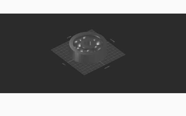
How to Design Ball Bearing Using SelfCAD
Designing a ball bearing is a complex yet fascinating process that bridges the gap between mechanical engineering and digital design. Ball bearings are essential components in numerous machines, reducing friction and enhancing efficiency. With advancements in 3D design software, creating precise and functional ball bearing models has become more accessible than ever. SelfCAD, a powerful and user-friendly 3D modeling tool, offers a perfect platform for both beginners and professionals to design intricate components like ball bearings with ease and accuracy.
In this article, we will walk you through the process of designing a ball bearing using SelfCAD. Our comprehensive guide will cover everything from the basic principles of ball bearing design to detailed step-by-step instructions for modeling in SelfCAD. Whether you're a seasoned engineer or a novice designer, you'll find valuable insights and practical tips to help you create a high-quality 3D model of a ball bearing.
To access the interactive tutorial to this article, check out https://www.selfcad.com/tutorials/71582s3lm4u2b1r3z50w6x356c4tzy11z471
Once you’ve launched the editor;
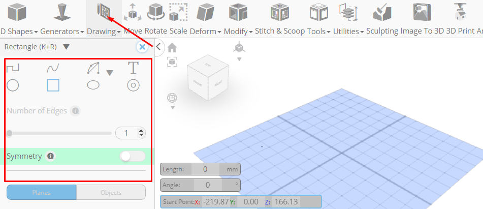
From the Drawing category on the Toolbar choose 3D Sketch
From the Tool panel choose Rectangle. Set Symmetry to true
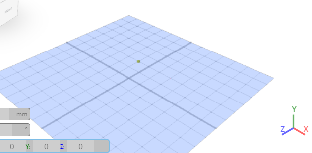
Set Snap to Grid Vertices to true
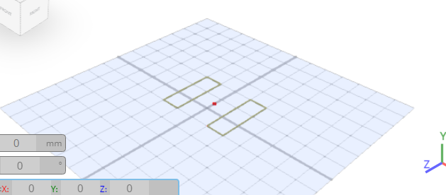
Click on highlighted point to draw rectangle
Click on highlighted point to draw rectangle
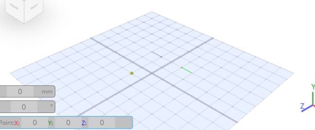
Click on highlighted point to draw rectangle
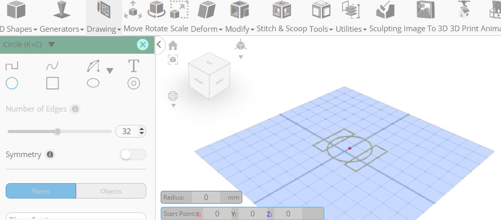
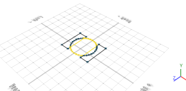
From the Tool panel choose circle
Set Symmetry to false
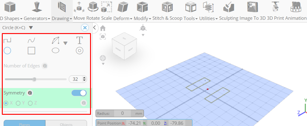
Click on highlighted point to draw Circle
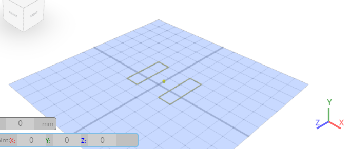
Click on highlighted point to draw Circle
Click ‘x’ to close 3D Sketch panel
Click to activate Edge Selection
Click on highlighted region to select it
Click Delete button to delete selected object
From the Tools category on the Toolbar choose Revolve. Set Segments to 50
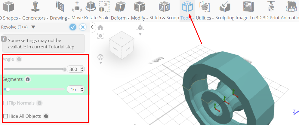
Click to finalize Revolve
Click Rotate on the Toolbar. Set x to 90
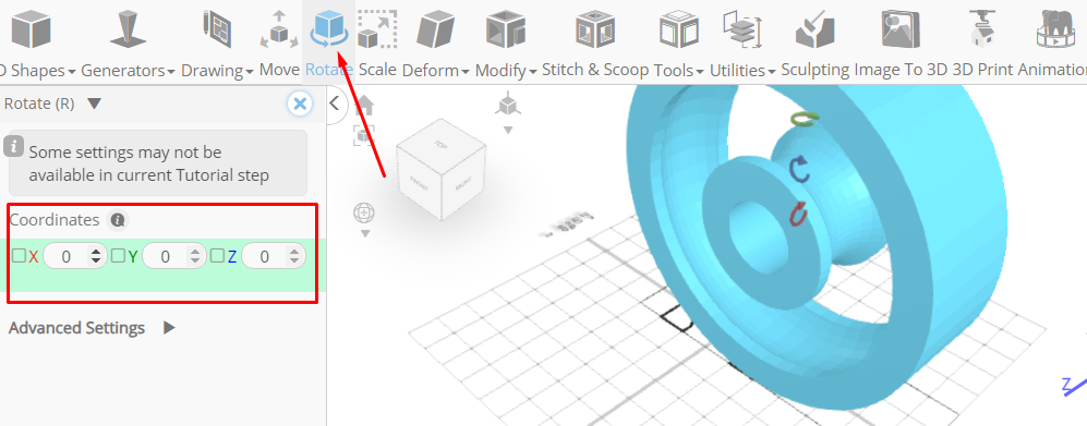
Click ‘x’ to close Transformation panel
Click Move on the Toolbar. Set x to 0. Set y to 0. Set z to 0
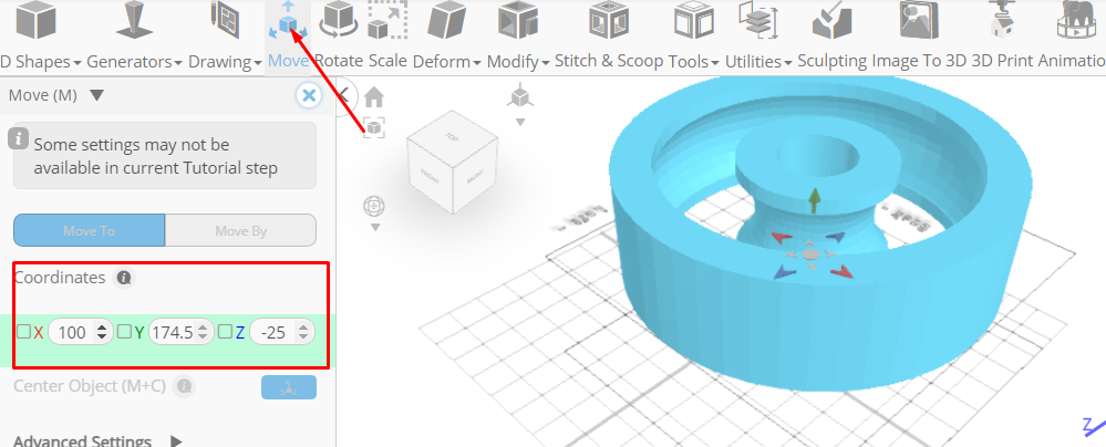
Click ‘x’ to close Transformation panel
From the 3D Shapes category on the Toolbar choose Sphere. Set Radius to 70, Position x to 145, Position y to 5
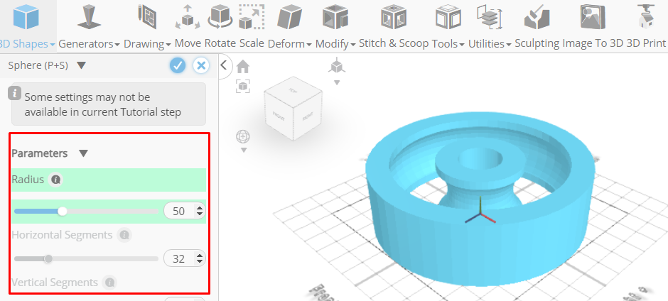
Click to finalize Sphere
From the Tools category on the Toolbar choose Copy offsets
Set Operation to Pivot. Set Amount of copies to 5. Click Copy button to create copies
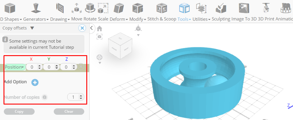
Click ‘x’ to close copy offsets panel
From the Edit Menu on the Top Toolbar choose Group
Click on revolved mesh 1 to select it
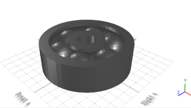
Click Color picker button to change color of selected object, Click silver button
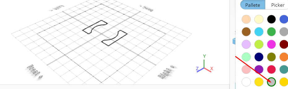
Click OK button to confirm color change
From the right panel choose Materials, Set Material type to Physical material, Set Metalness to 0.7
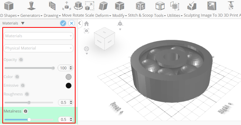
Click to finalize Materials
Click Inverse selection button to inverse selection
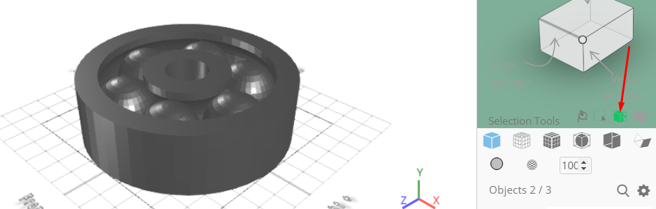
Click Delete button to delete selected object
As you continue honing your design skills, remember that SelfCAD offers a wealth of resources to support your learning journey. To deepen your understanding and explore more advanced features, consider checking out the interactive tutorials (https://www.selfcad.com/tutorials) available on the SelfCAD website. The tutorials page provides a treasure trove of guides, tips, and tricks that cater to designers of all levels.
More structured learning experience can also be accessed at the SelfCAD Academy (https://www.selfcad.com/academy/curriculum/), https://www.youtube.com/@3dmodeling101, and 3D Modeling 101 series (https://www.youtube.com/playlist?list=PL74nFNT8yS9DcE1UlUUdiR1wFGv9DDfTB). This comprehensive resource offers in-depth courses taught by industry experts, allowing you to master the intricacies of SelfCAD at your own pace.