How to Create & Mate Simple Parts on SolidWorks
by kwalt10 in Craft > Digital Graphics
6293 Views, 2 Favorites, 0 Comments
How to Create & Mate Simple Parts on SolidWorks

This Instructable is a step-by-step tutorial on how to create basic boxes on SolidWorks and mate them together. SolidWorks is an extremely effective modeling tool for engineers, and you can even use it to print 3D parts from a 3D printer. After completing this Instructable, you will have an understanding of SolidWorks and how to both create and combine parts. You will also be able to go on and create more complicated parts and assemblies with the knowledge learned from this tutorial.
For these instructions to be of use, you must be carrying them out on a computer with SolidWorks previously installed.
Getting Started
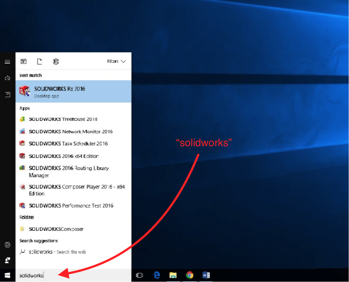
Search for “SolidWorks” in the search bar on the desktop of the computer. Click on SolidWorks 64 bit edition.
Opening SolidWorks
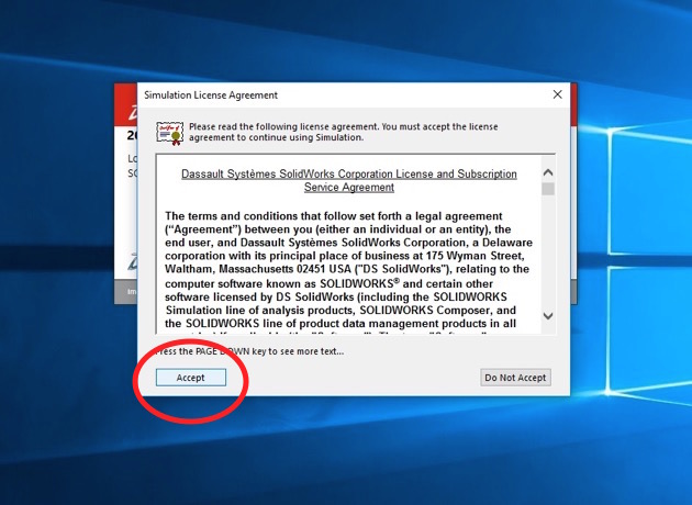
After opening SolidWorks, you will see two separate pop-ups. Press “Accept” for each pop-up.
Beginning Your Project
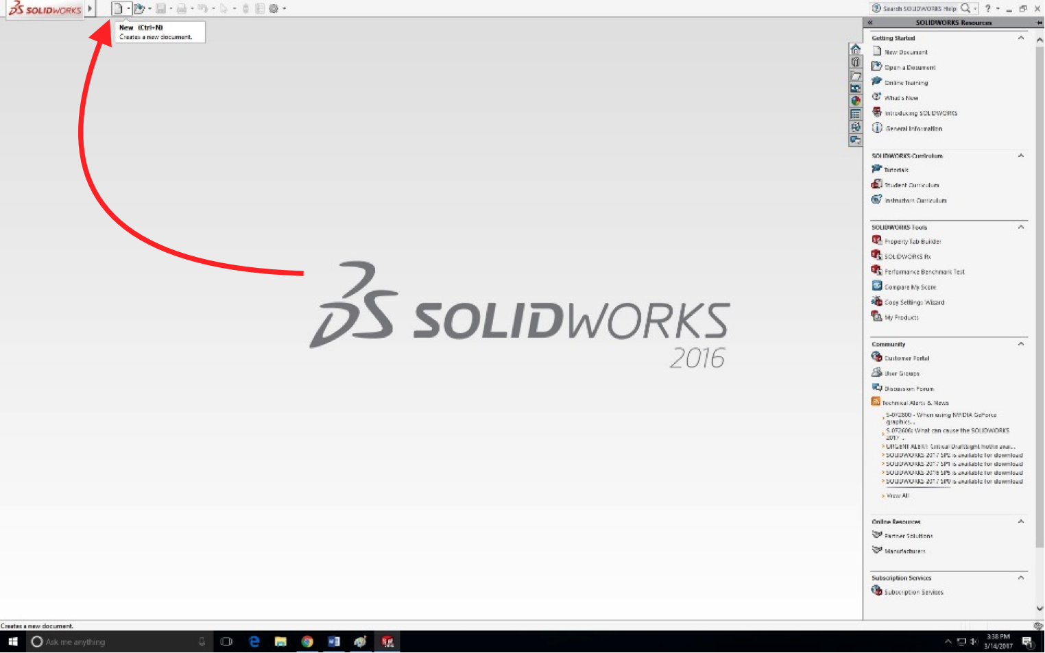
A home screen will appear. In the upper left-hand side, you will find the “New Document” button. Click this to start a new document.
Creating Your Part
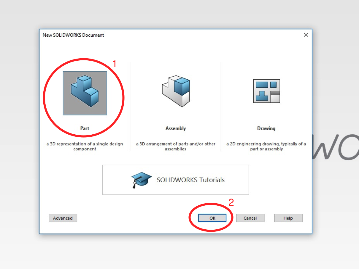
A screen will appear giving you three options to choose from: a part, an assembly, and a drawing. For this tutorial, we will be using two of these: parts and assemblies. For this step, choose “Part” and then click “OK.”
Orienting the Plane
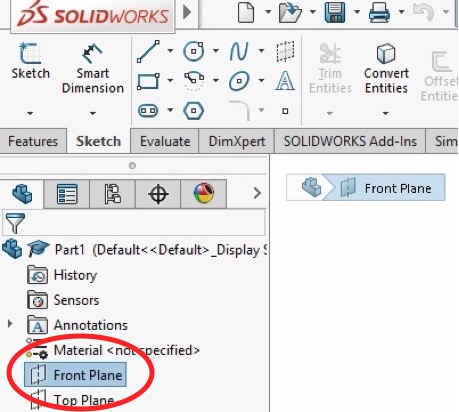
A new menu will be on the left side of the screen. Click on “Front Plane” to choose the plane in space you will be creating your box from.
Orienting the View– Part 1

In order to make the plane face towards you instead of at an angle, click “View Orientation” as seen in the photo.
Orienting the View– Part 2
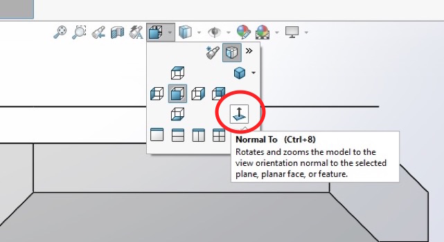
A pop-down menu will appear. Click “Normal To,” or, the square with an arrow coming straight up out of it. This will face the plane toward you.
Starting the Sketch
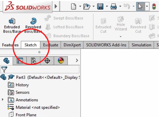
Now that the plane is facing you, it’s time to draw the square. To do this, you need to first open the “Sketch” tab.
The "Corner Rectangle" Tool
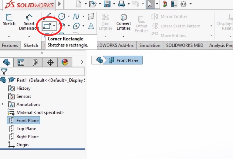
To do draw the square, click the “Corner Rectangle” tool pictured and located in the top left-hand corner.
Drawing the Square
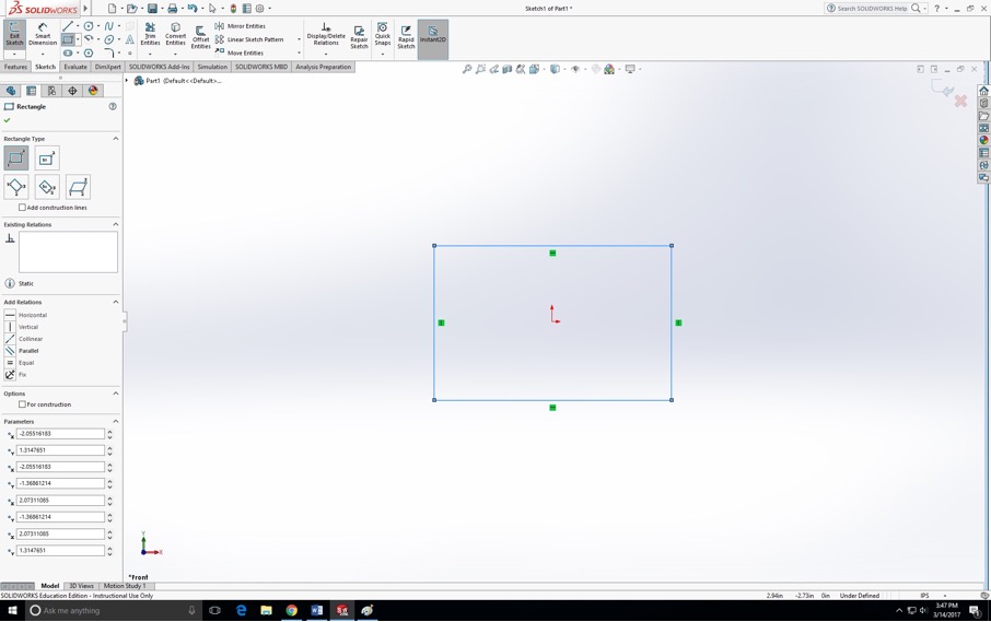
Once the “Corner Rectangle” tool is selected, click within the plane. Without releasing the cursor, drag the mouse so that you create a square. Then, release the mouse. At this point, the size of the square does not matter.
The "Smart Dimension" Tool
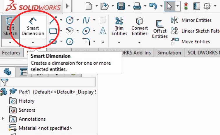
Then, in the top left-hand corner, select “Smart Dimension.” This tool allows you to precisely dimension your square to a 10x10 inch box.
Dimensioning the Box– Part 1
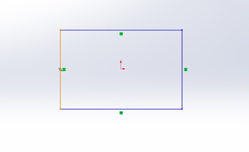
Then, move your cursor over one of the vertical sides of the box and click once a whole side is highlighted. I arbitrarily chose the left side, but choosing the right side of the box will do the same thing.
Dimensioning the Box– Part 2
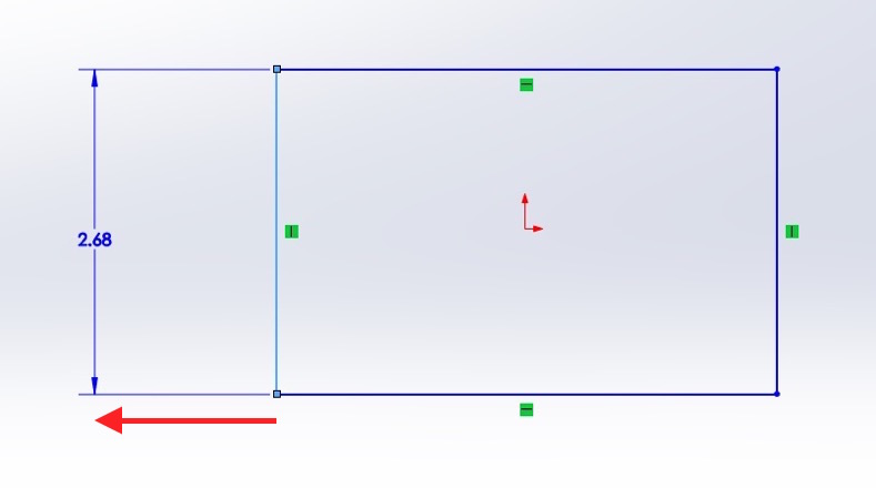
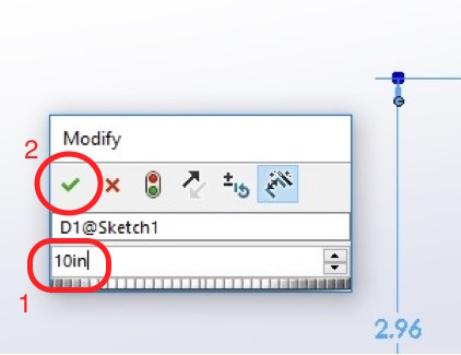
After selecting a vertical side, move your cursor away from the box. Then, click once you move a couple inches away. A small box will then appear detailing the dimension of the side. In the second box, type in “10in” as the arbitrary length we will use for this Instructable. Once you have entered the desired length, click the green check mark found in the upper left-hand corner.
Dimensioning the Box– Part 3
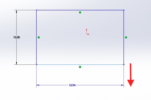
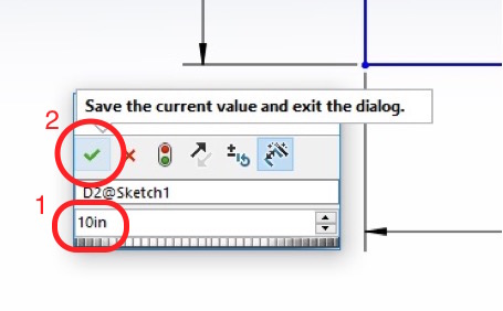
You will then repeat Step 13 with one of the horizontal sides of the square. Again, you will use 10in to dimension this side.
Finishing the Sketch
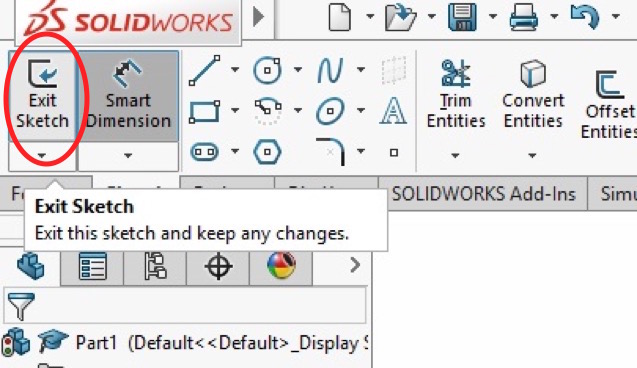
After dimensioning the entire square, click on “Exit Sketch” in the top left-hand corner.
The "Features" Tab

Click on the “Features” tab on the far left side of the toolbar. This tab display will what can be done with this dimensioned square.
Beginning the 2D to 3D Transformation
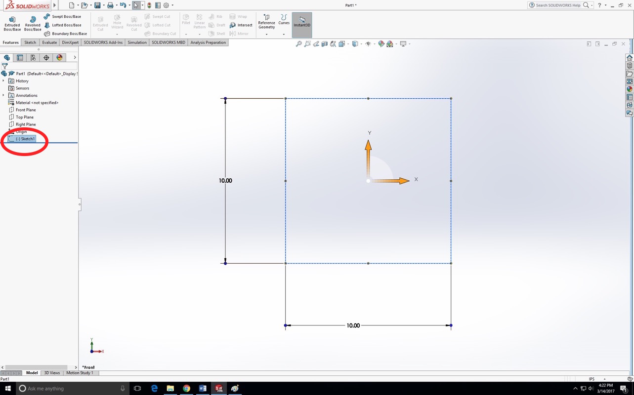
Then, click on “Sketch1” on the menu on the left side of the screen. This will select your dimensioned square so that it can be converted from 2D to 3D.
The "Extruded Boss/Base" Tool
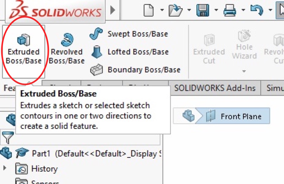
Click “Extruded Boss/Base” in the top left corner. This button makes your 2D square into a 3D box. Your square will no longer be referred to as a “Sketch” within the application now that it is three-dimensional. Now, your square will be referred to as a “Boss.”
Boss Depth Adjustment
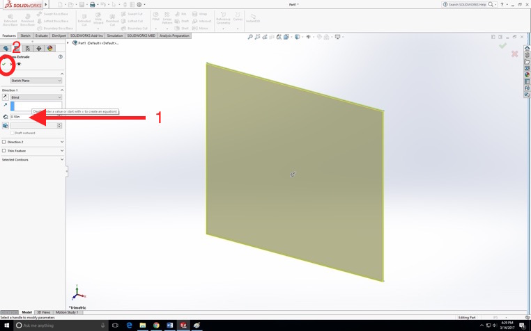
Now that you have “extruded the boss,” a new menu appears on the left side of the screen. This screen details the different aspects of your now 3D box. However, we will only focus on one feature: the depth of the box. In the box detailing the depth of your box, change the existing value to “10in.” After changing the depth, click the green check mark to officially create your 10x10x10 inch box.
Save Your Box
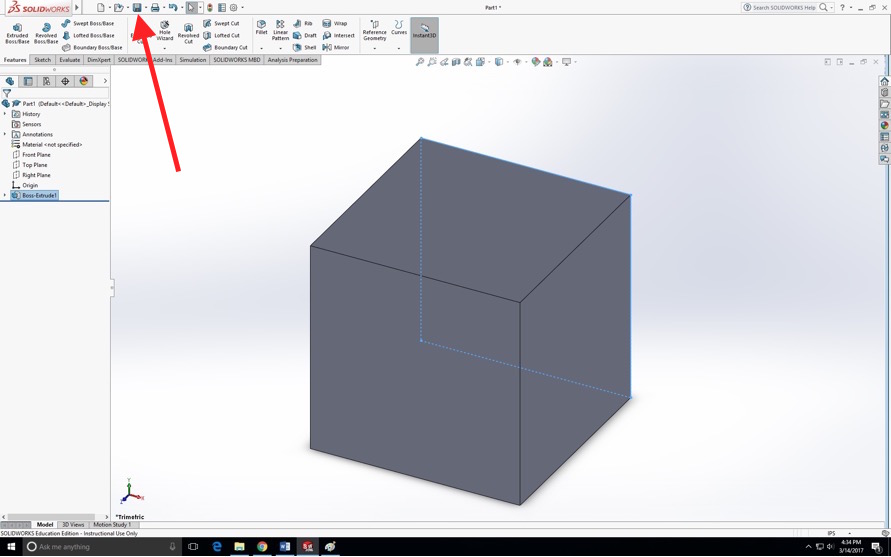
You have now created a 3D 10x10x10 inch box in SolidWorks. You should also notice that your “Sketch1” has become a “Boss-Extrude1.” Now, save your box as “Box” in a folder that you remember and can easily reach.
Creating the Second Box
Now, you will create another box in another file by repeating steps 3-20, but replace “10in” with “5in” every time you dimension your other box. In addition, save your second box as “Box2.” Make sure to save this part in the same folder as your other part, “Box.”
Adding Color to Your Box
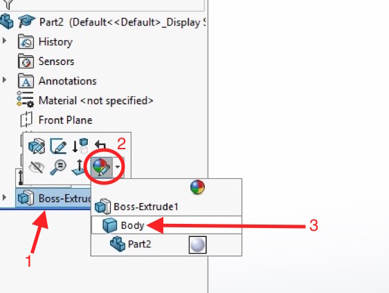
An additional step you can add to your second box is coloring it a different color. To do this, click on “Boss-Extrude1” in the menu on the left. Once you click on it, a hovering menu will appear above it. In the bottom right corner is a circle with different colors and a pencil. When you click on this icon, another hovering menu will appear. In this menu, click on “Body” to select the entire box so that you can change its color.
Selecting Your Color
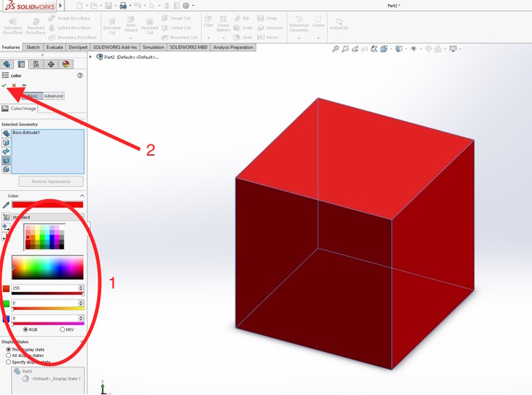
With the “color” menu pulled up, select any color from the available options. I chose red so that this box would stand out from the other box. Once you’ve selected your color, click on the green check mark in the upper left-hand corner. Save your file again.
Creating an Assembly
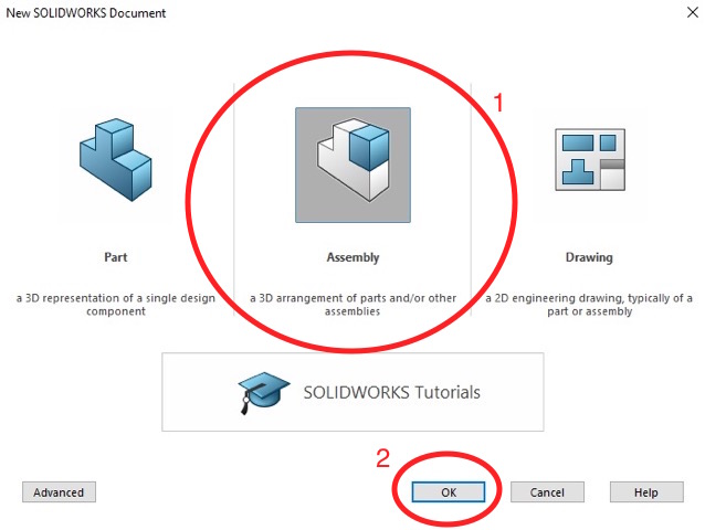
Open another new document. Except this time, click on “Assembly” instead of “Part.” This is because we are combining two separate parts to create an assembly of parts. After selecting “Assembly,” click “OK.”
Changes to Notice
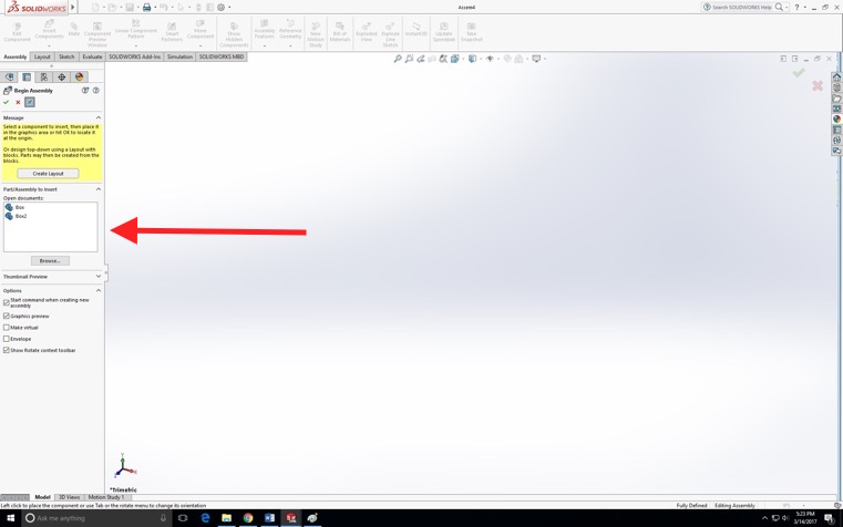
This starting screen will look slightly different than the starting screen for creating parts. Notably, the menu on the left will have a section titled “Part/Assembly to Insert” with your other two parts (Box and Box2) in a white box.
Placing Parts– Part 1
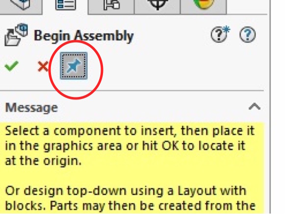
Before you can assemble your part, you need to click the pin at the top of the menu. This will allow you to place multiple parts in the assembly document easily.
Placing Parts– Part 2
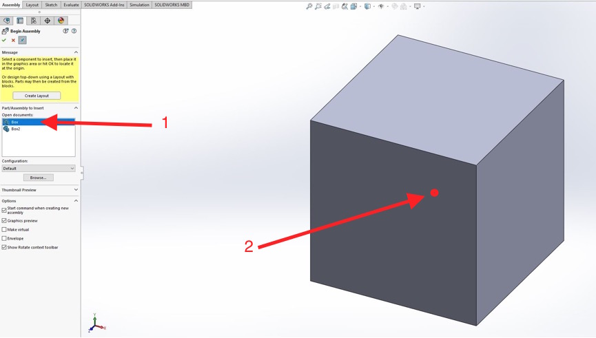
Click on “Box” and then place it in the assembly by clicking in the grey space. After this, another box will automatically appear and follow your cursor around. Do not click to try to get rid of it, as it will place another copy of the box.
Placing Parts– Part 3
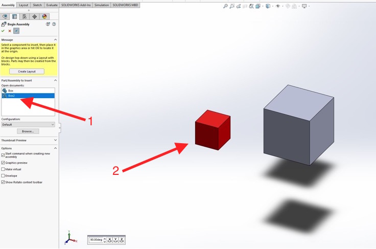
Without clicking to place a duplicate box, click on “Box2” and do what you did in Step 27 and place your smaller box next to your other, already placed larger box. Now, click the green check mark above to finish placing parts in the assembly
The "Mate" Tool
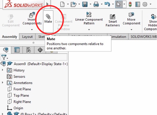
With your two boxes placed, click “Mate” in the top menu. This will open a new menu that will help you finish your assembly with ease.
Mating the Faces– Part 1
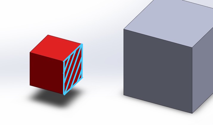
Connecting the two boxes requires three mating points. To make the first “mate,” select a part of one box. For the purposes of this tutorial you will select three different kinds of point to mate. First, select a face of the red square.
Mating the Faces– Part 2
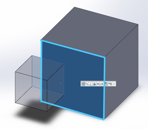
Select a face (a flat square that makes up one of the sides of the square) of the grey square. Notice how once the two points that will be mated have been chosen, the squares orient themselves properly. To finish off this mate, click the green check mark.
Mating the Edges– Part 1
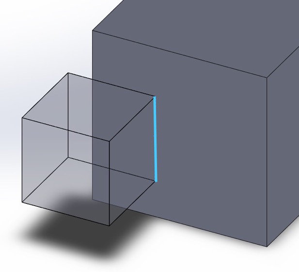
For the second mate, choose an edge (where two faces come together) of the red square.
Mating the Edges– Part 2
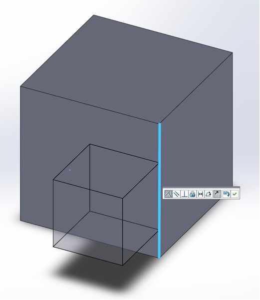
Now, select an edge of the grey square that is on the same side as the face chosen before so that the two squares will connect at their respective sides. Click the green check mark to finish.
Mating a Point– Part 1
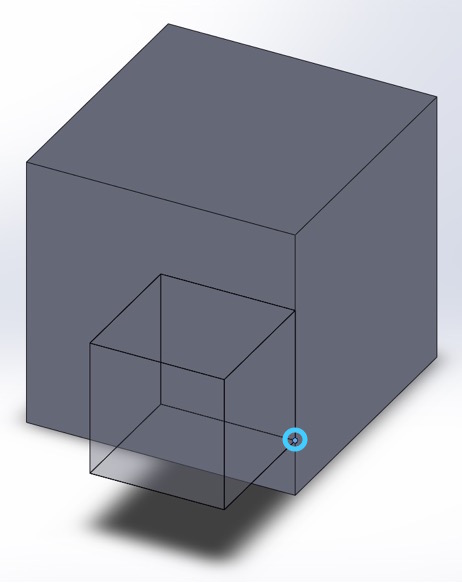
For the third mate, select a point (where three edges come together) on the red square on the same side that you mated in the previous step.
Mating a Point– Part 2
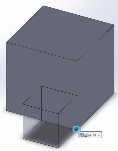
Select a point on the grey square on the same side that you used to mate earlier. Click the green check mark to finish.
Finishing Up the Mated Assembly
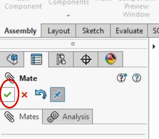
Now that you have made three mates, you can finish mating the two boxes together. To do this, press the green check mark twice.
Finished!
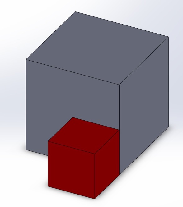
You have now completed an assembly!
With this knowledge, you can complete more difficult assemblies and parts in SolidWorks. Although seemingly simple, this tutorial's concepts are core ideas that are constantly being used throughout SolidWorks– no matter how complicated the design.