How to Create 3D Printed Organic Forms and Vases
by ajreynolds15 in Living > Decorating
9696 Views, 47 Favorites, 0 Comments
How to Create 3D Printed Organic Forms and Vases
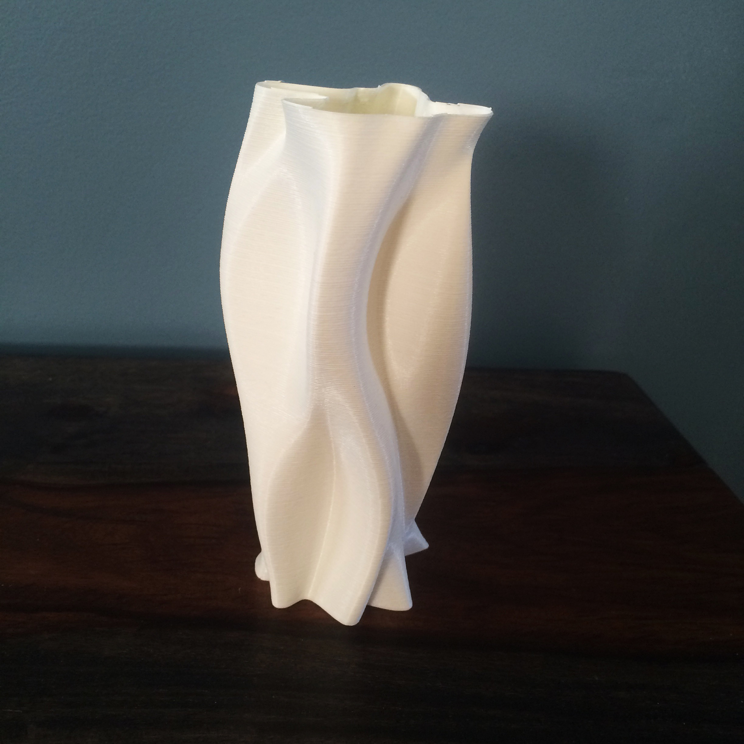
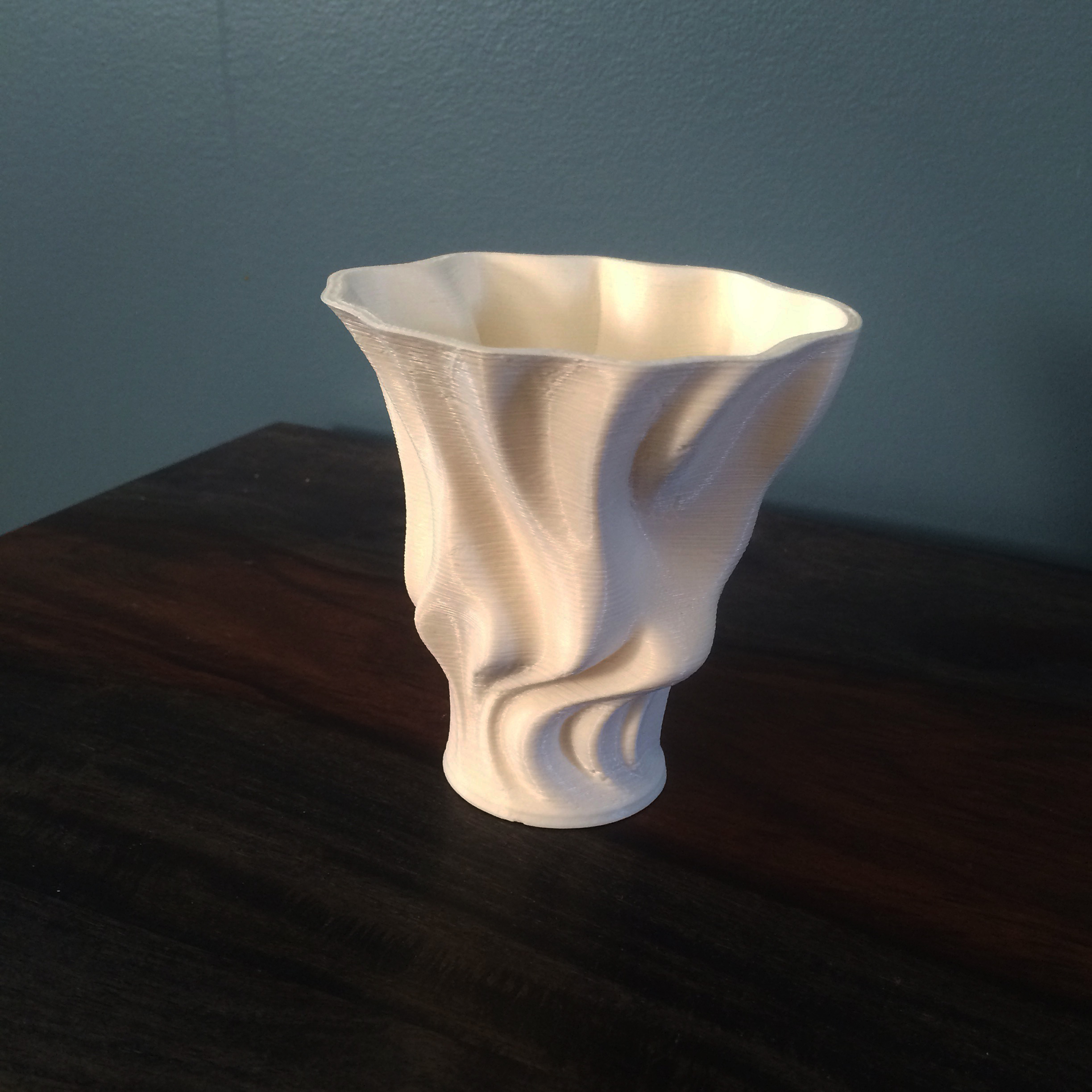
In this Instructable I will be showing you how to 3D model Organic Forms and objects in Rhino so that they can be made into vases when 3D Printed.
Rhino is a 3D Modeling program that I use often for creating 3D Models to be 3D Printed.
I will show you a highly detailed step-by-step instruction of the workflow within Rhino from start to finish of how to loft free-from curves that will make an aesthetically beautiful 3d Printed Vase.
Draw a Circle
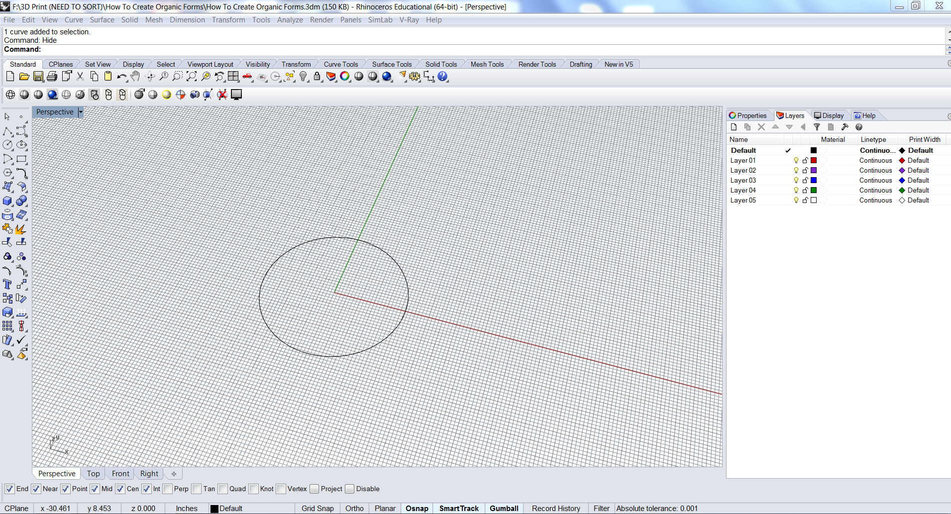
When creating a vase or a similar object in rhino, I typically start by drawing a circle as a guideline for the free-form control points to be centered around and to have a general idea of the sizing of the object.
Draw a Free-Form Curve
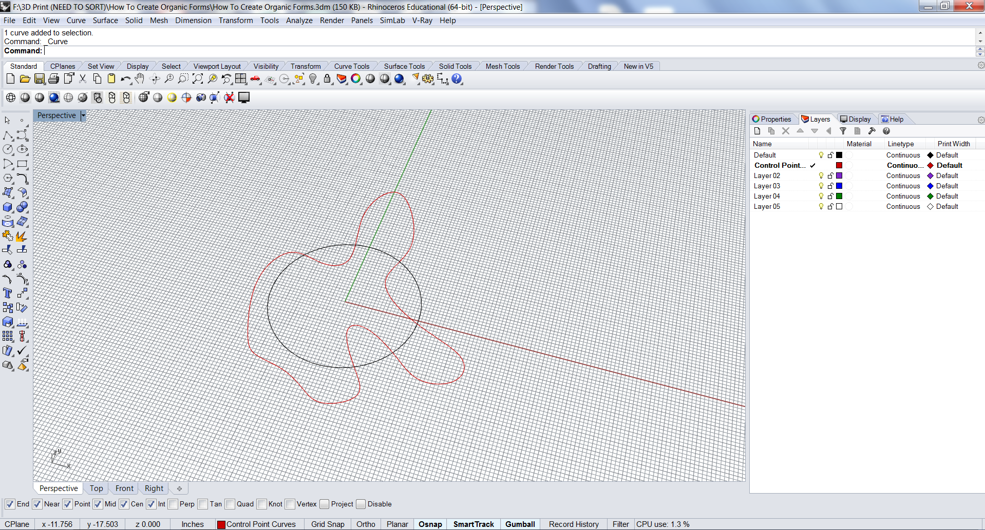
Start by drawing the free-from curve by using the control point curve tool located on the left toolbar.
The shapes can be up to you however way you want them to be structured. They can be completely arbitrary or you can follow a much more methodological method of where to place the curves.
For this demonstration I will just create random control points to make a squirming curve around the circle.
It is important to make a closed curve - meaning that where you end must be at the same point as where you started.
Draw Multiple Curves
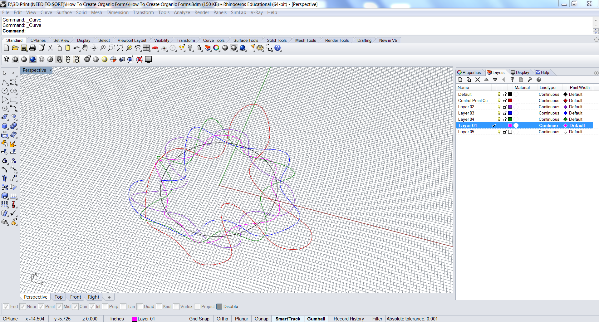
Add as many different variations as you wish around the first drawn circle.
I have drawn 5 different curves and put them on different layers so that they are easier to see for the demonstration.
I would also suggest turning off the "Object Snap" located at the bottom of the screen because I want these curves to be varying from one to the next and I do not want them to be sharing control points.
Select First Curve
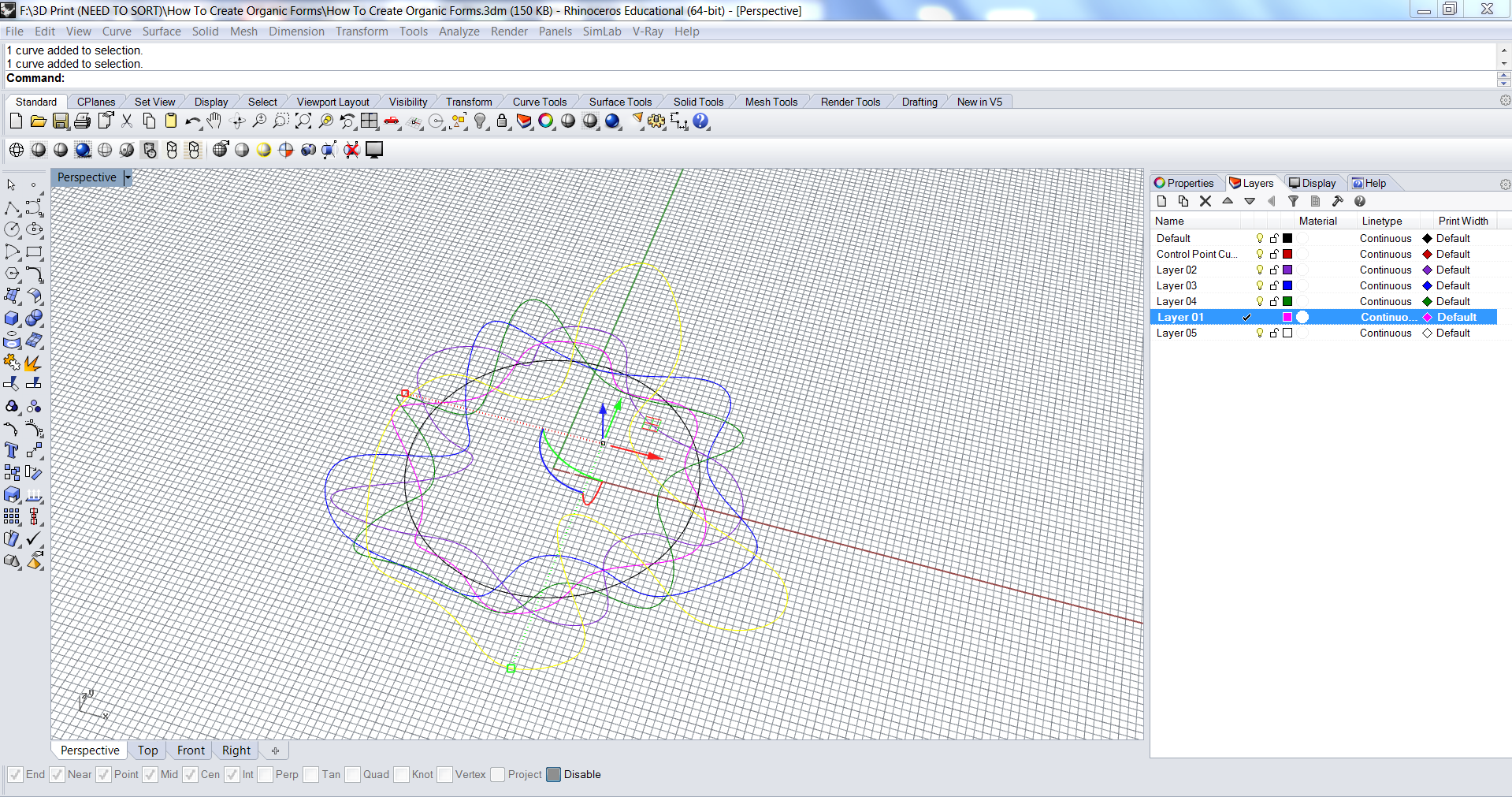
Once you have all of your curves drawn, you will select one of the curves and use the Gumball Tool to move the curve in the Z axis. The height you use to move the selection up is based on your preference but for this example I used 5 inches.
Offset Heights
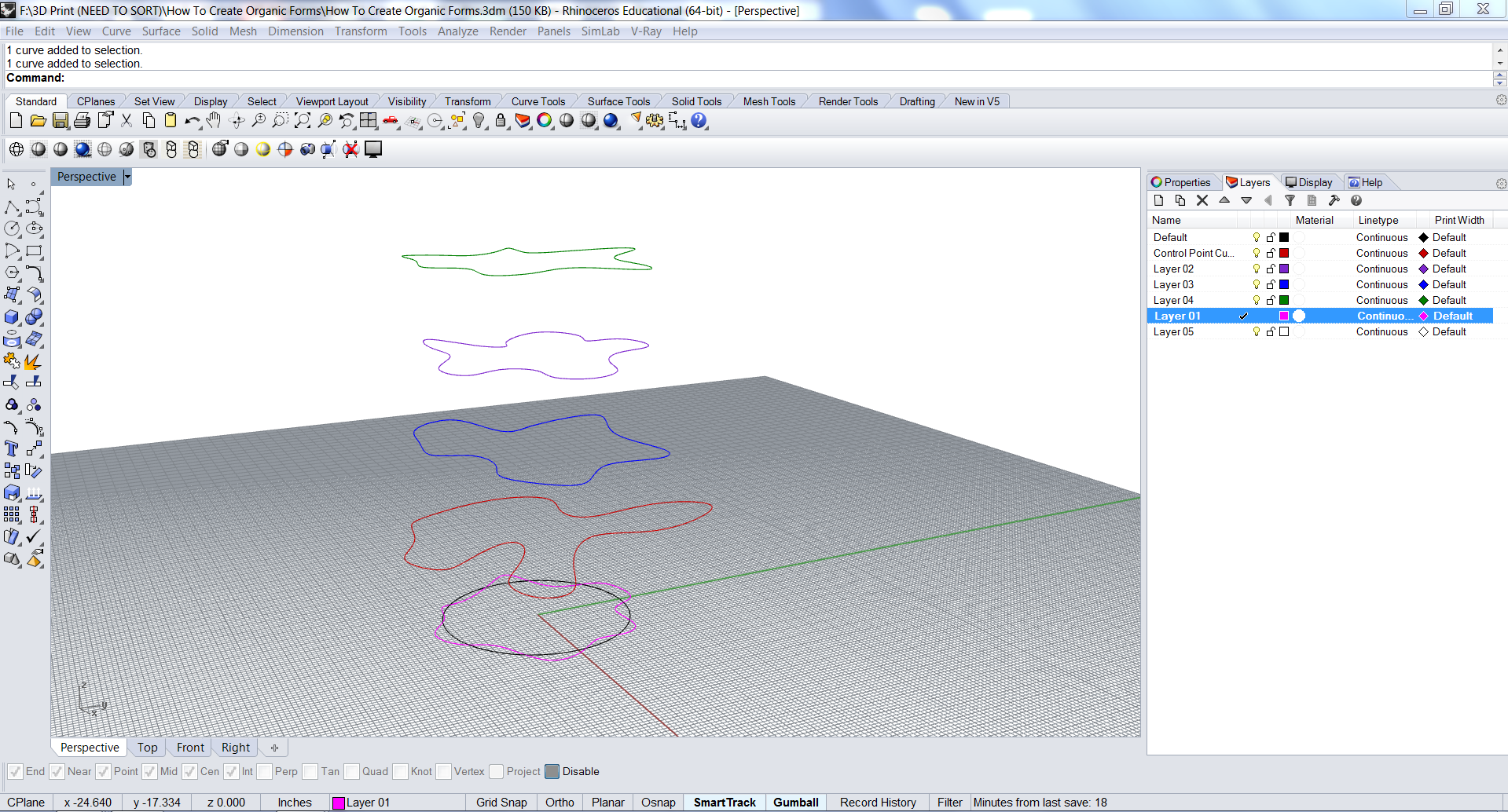
I turned off the layer that the original circle was on because we do not need it anymore after we had drawn our free-form curves.
Offset the heights of the free-form curves by different variables.
There is a lot of trial and error with this type of design so you can experiment with different heights of how far apart from each curve you want them to be spaced. For this demonstration I am just going to be spacing all of the curves evenly apart in the Z-axis direction by 5 inches.
Loft Curves
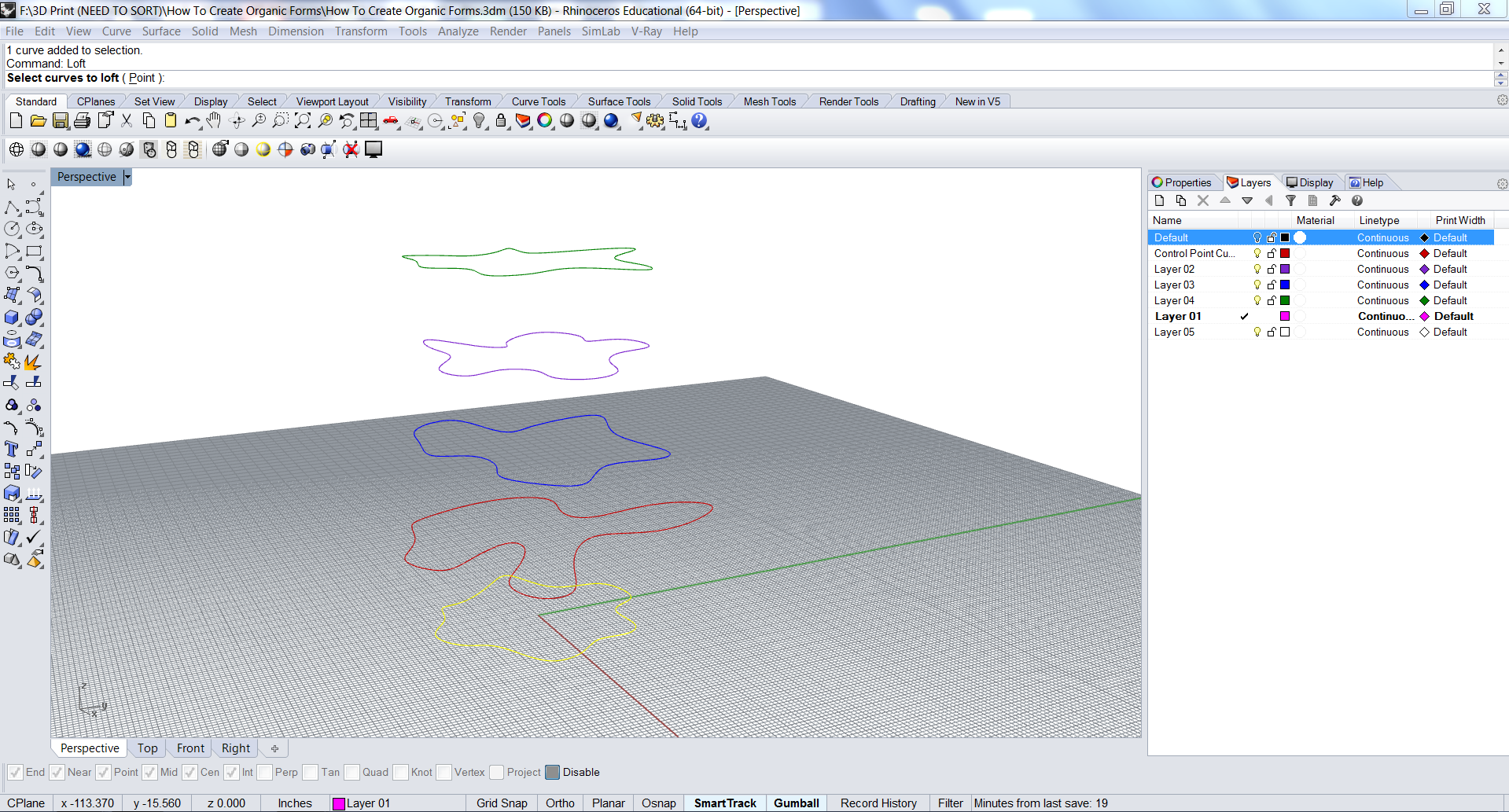
The next step involves lofting the curves.
Do so by typing into the Command Bar: Loft
When lofting curves it is very important to select the curves in order in which they are to be lofted. This is why I have selected the bottom curve first and will select one by one each curve that is next in line above.
Drag Seam Point to Adjust
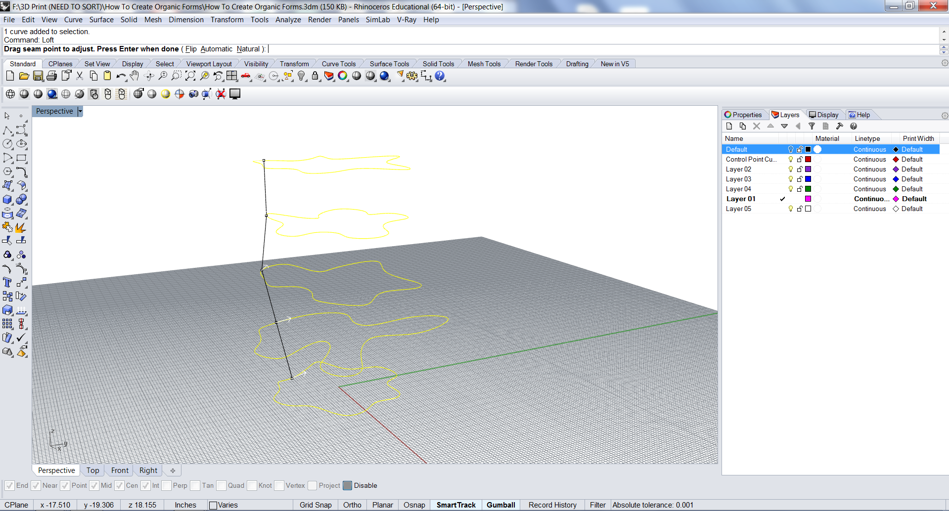
After the curves have all been selected and pressed enter, you will have an option to Drag Seam Point to Adjust.
When this shows up I typically select "Natural" to have the free-flowing loft and is quite easy to adjust.
This is telling which control points to flow from and creates the outer surface.
Loft Options
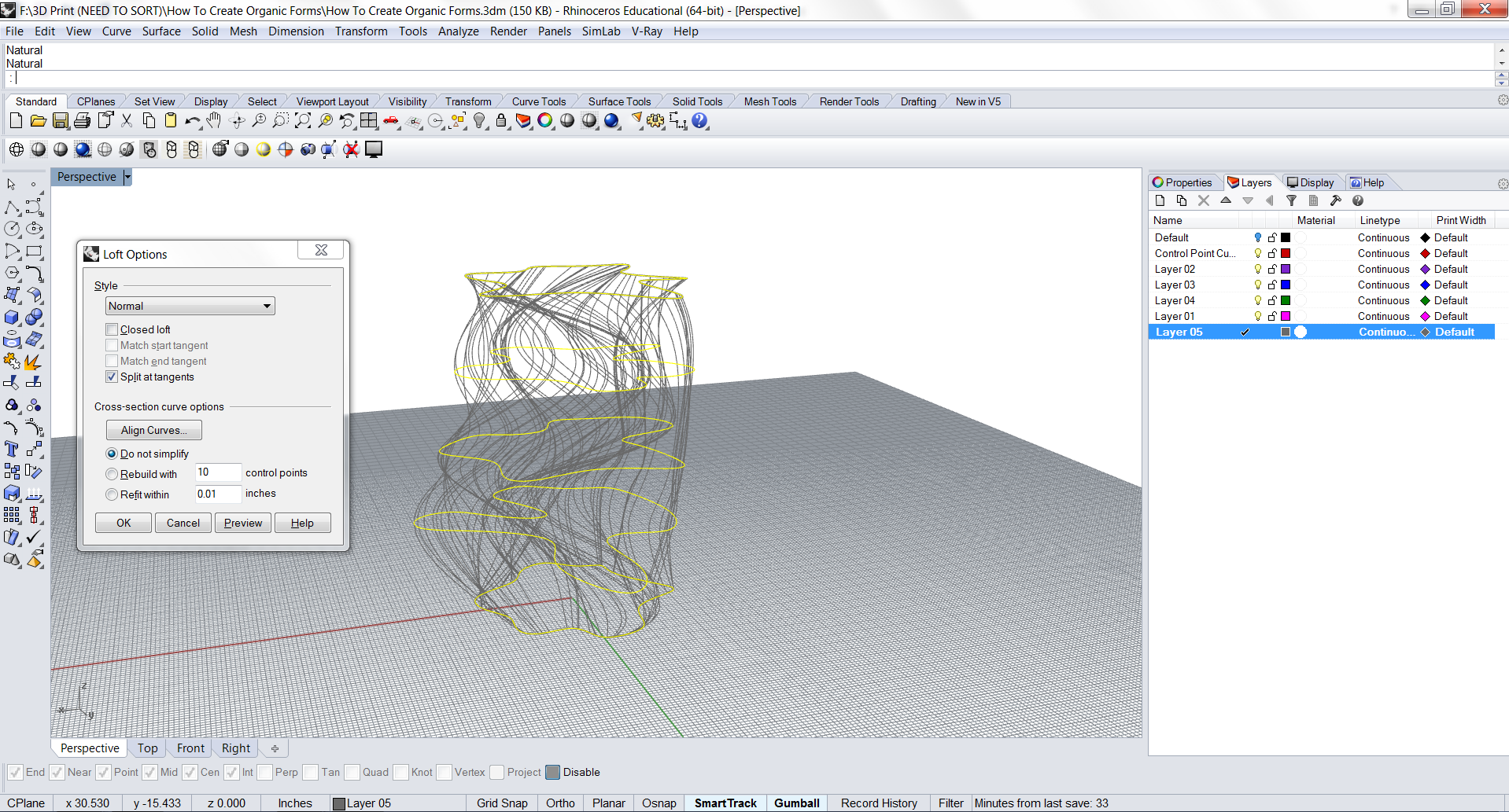
After pressing Enter, the Loft options box will appear.
This will bring up a preview of the curves that are being lofted.
Rendered Preview
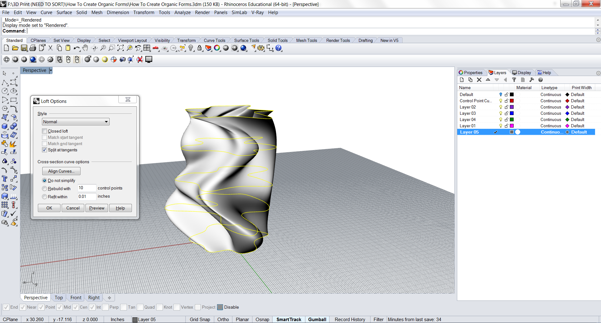
Set the viewing mode to either Rendered or Shaded to have a look at a preview of the newly lofted surface that you have just generated.
Styles
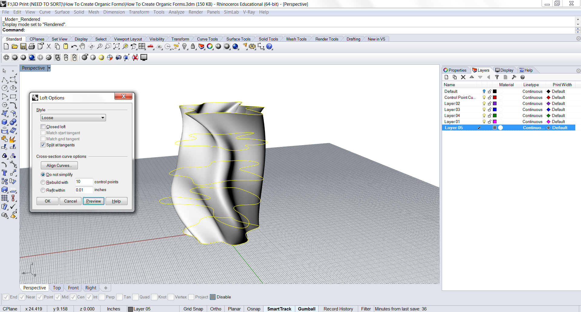
Click through the different styles and update the rendered view of the model by clicking preview within the box.
In this example I selected "Loose" to show the change in the form.
Click through the styles until you find one that you prefer.
Open Surface
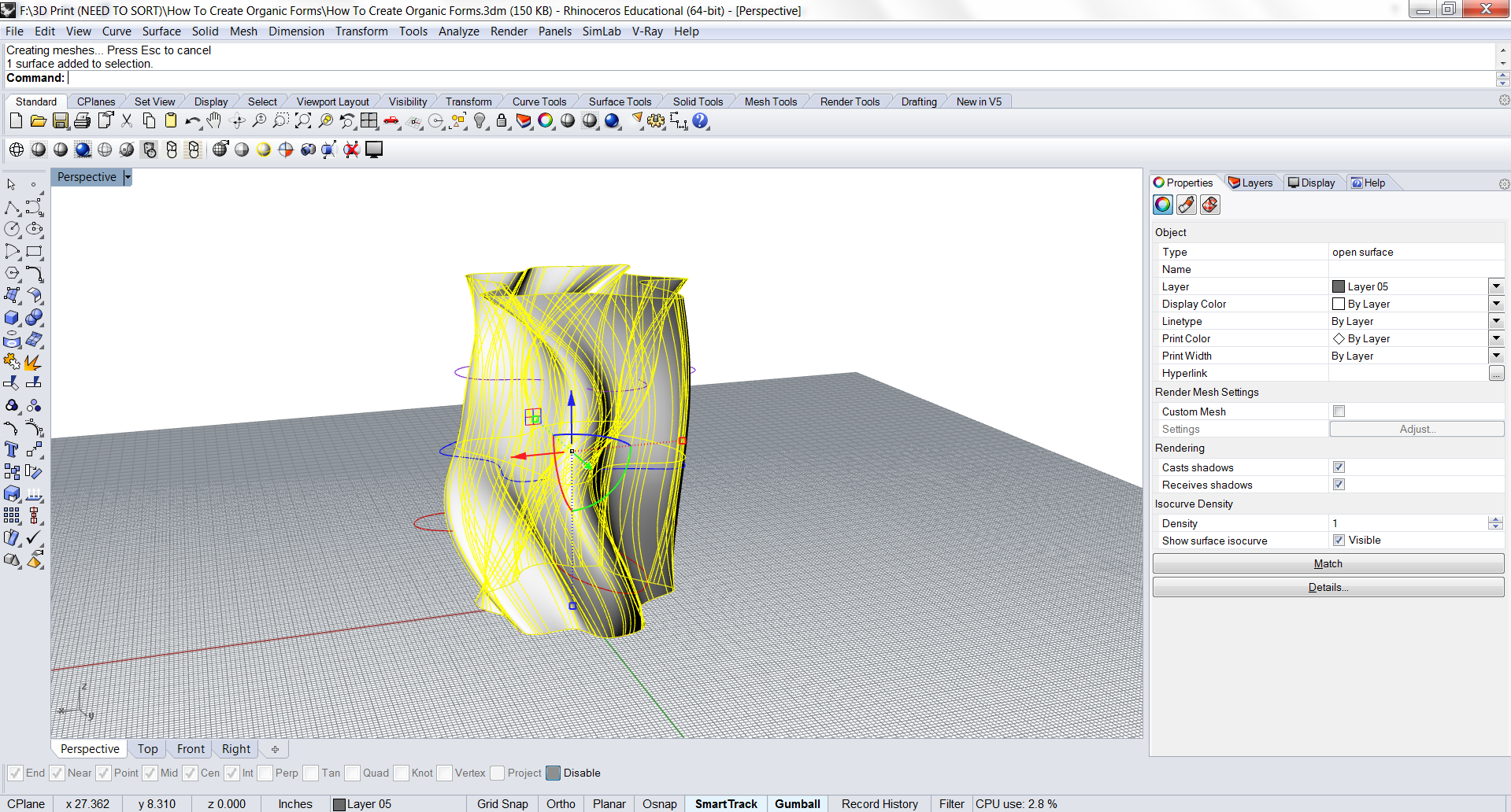
For the example of this instruction I will stick with the "Loose" style and then click "Enter". If you select the newly lofted surface and go into the properties tab on the right side of the screen, you will notice that this new object has an object type of an "Open Surface".
This can be a problem for the end goal of 3D Printing and I will show in the next step why this is an issue and how we can solve it.
Check for Volume
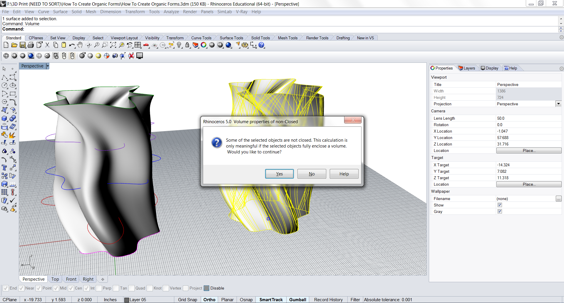
In this step I copied over the surface so that I have a back-up file just in case the original surface gets lost in the file somehow. To demonstrate how the open surface causes a problem with 3D Printing, I typed into the Command Line: Volume.
Volume is a tool within Rhino that shows the estimated volume of an object. For the volume to be calculated, the object has to be a solid, watertight model with ideally no non-manifold or naked edges.
Cap
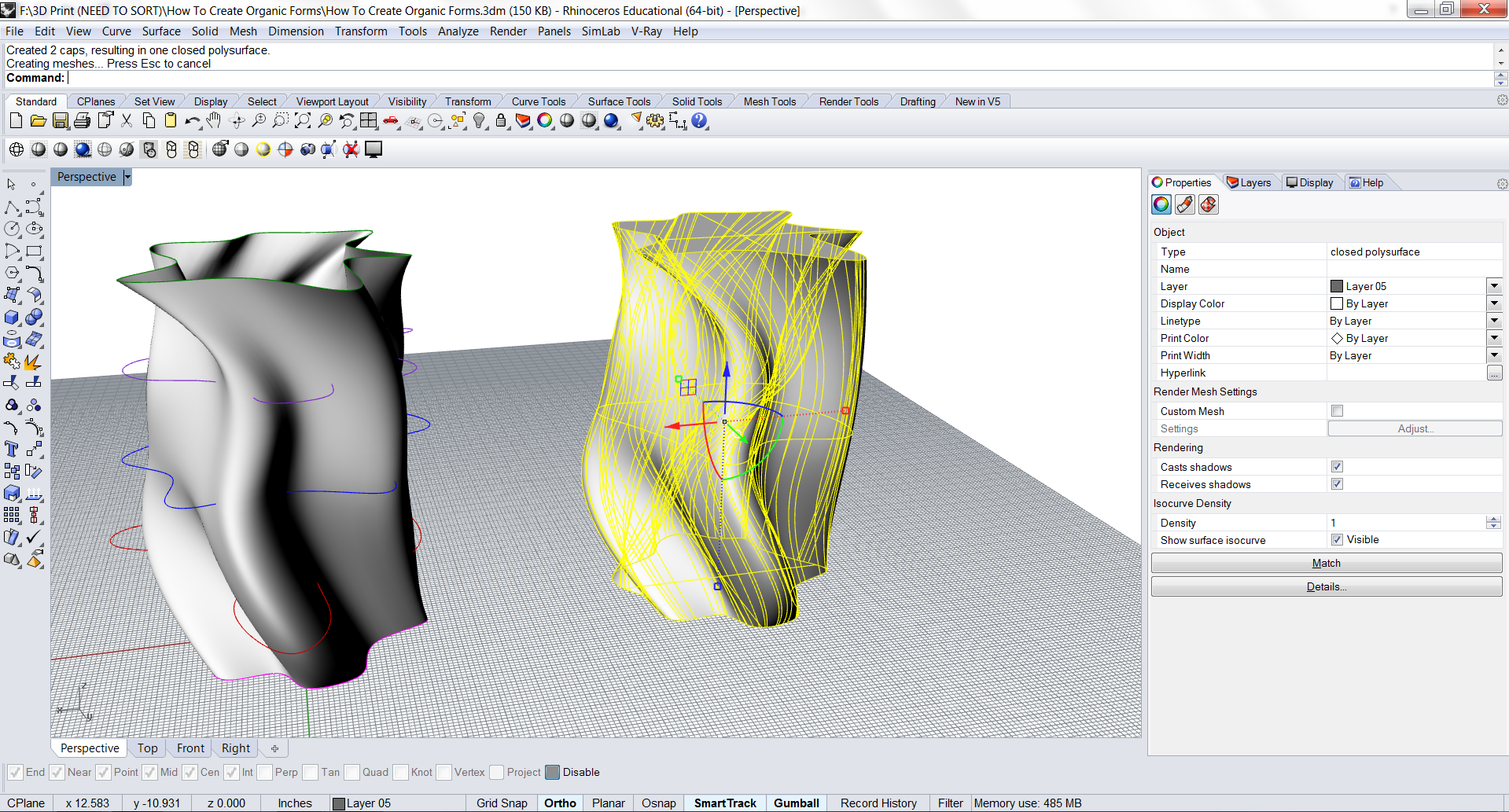
The easiest way to convert the lofted open surface that we created earlier into a closed solid object is by selecting the object and typing into the Command Line: Cap.
Cap is a tool within Rhino that is handy when trying to convert an open surface to a closed polysurface by finding the gaps within the object and finding Rhino's best solution.
Solid Volume
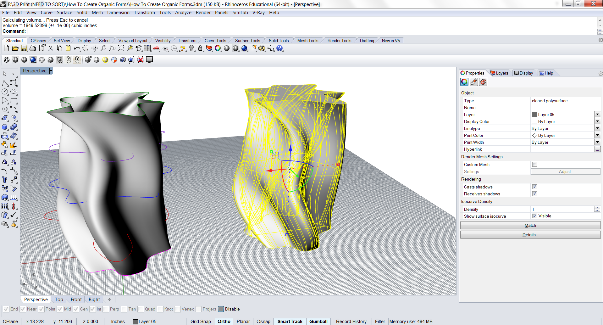
Now this time if we type into the Command Line: Volume. We will receive a volume for the object in cubic inches, or whichever measurement you are working in.
As mentioned before, this is just a demonstration of how to use the lofting tool so this example object will need to be scaled down dramatically to get the volume to a reasonable size for your 3D Printer.
The volume tool within Rhino is very useful because you can make an estimate on how much plastic material will be used when 3D printed.
Offset Surface
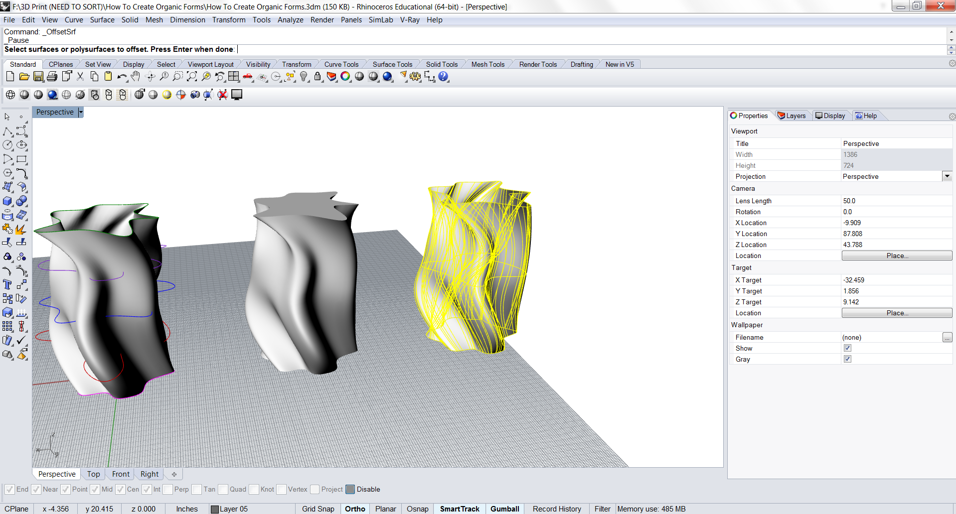
Another method for creating an open surface into a closed polysurface is by offsetting the surface to a specified distance. This is particularly useful if the end-goal of this process is to create a vase or lamp where the inside of the object needs to be hollow.
Interior Offset
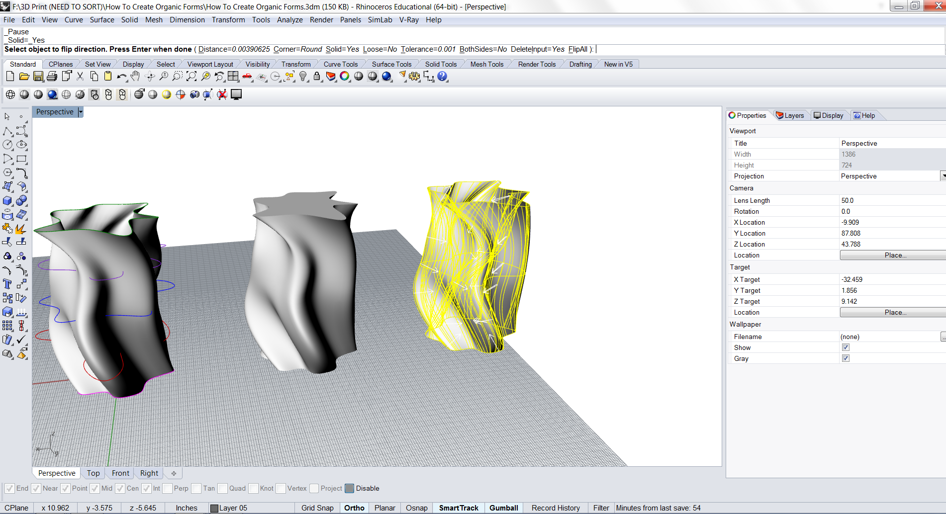
You can choose to offset the surface to the interior or exterior of the object. I typically offset towards the interior because I would like to preserve the aesthetic of the exterior.
Closd Polysurface
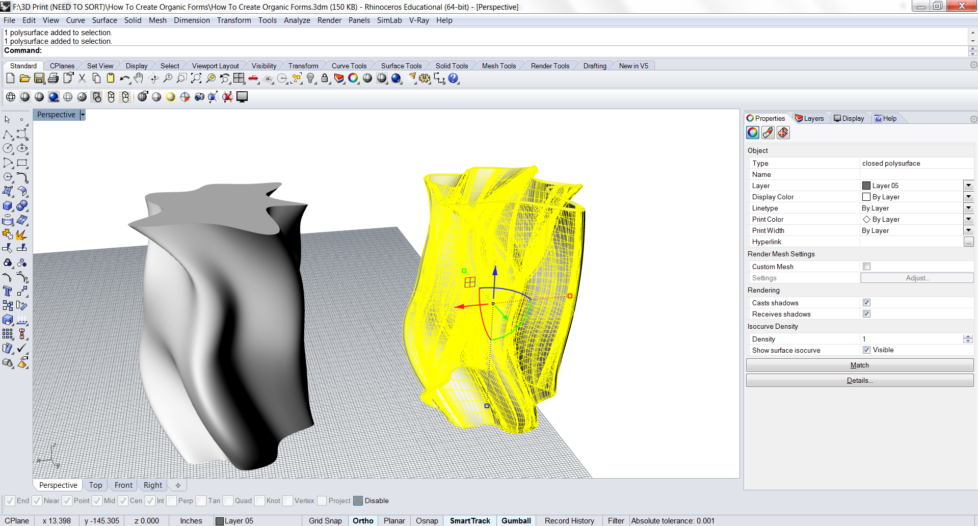
After offsetting the surface you will see that the object is now a closed polysurface and at the same time has a much higher density of curves compared to when we had just simply capped the surface earlier to make a solid object.
Solid Volume
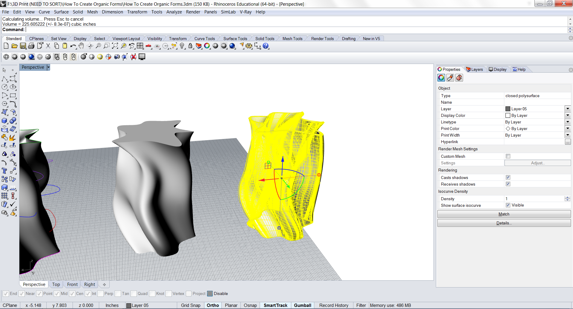
If you type in the Volume Command as we had done previously, you will notice that the volume of the object and how much material that will be used is much lower than before when we Capped the object to make a solid.
This is because the vase is hollow in the center and will not use as much material when 3D Printed.
Creating a Base for the Vase
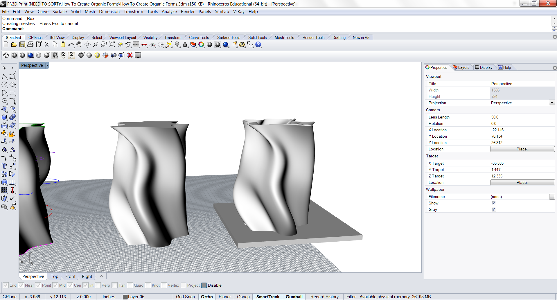
To create a Base for the Vase, simply draw a box that intersects with the vase you had just created.
Boolean Difference
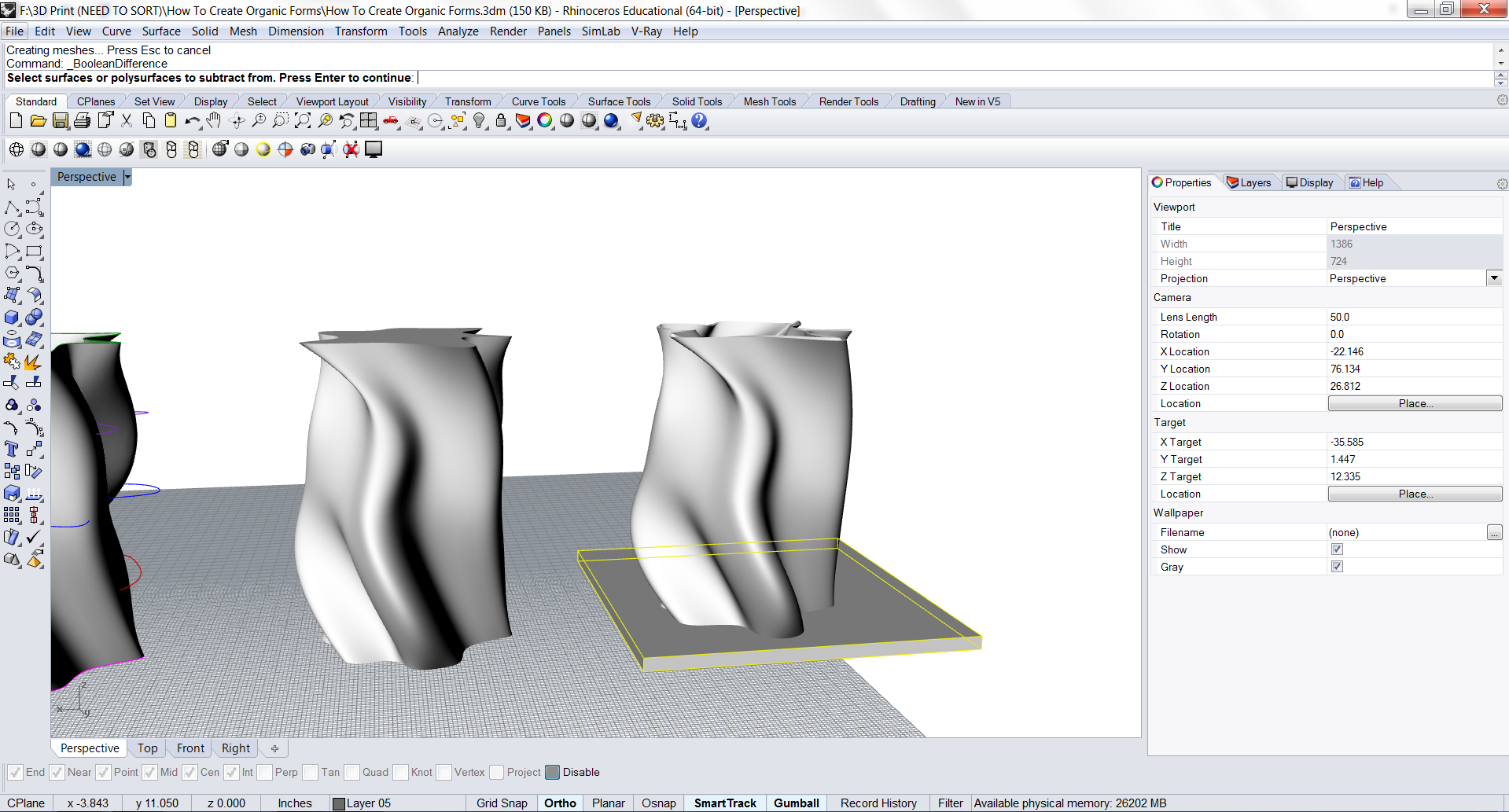
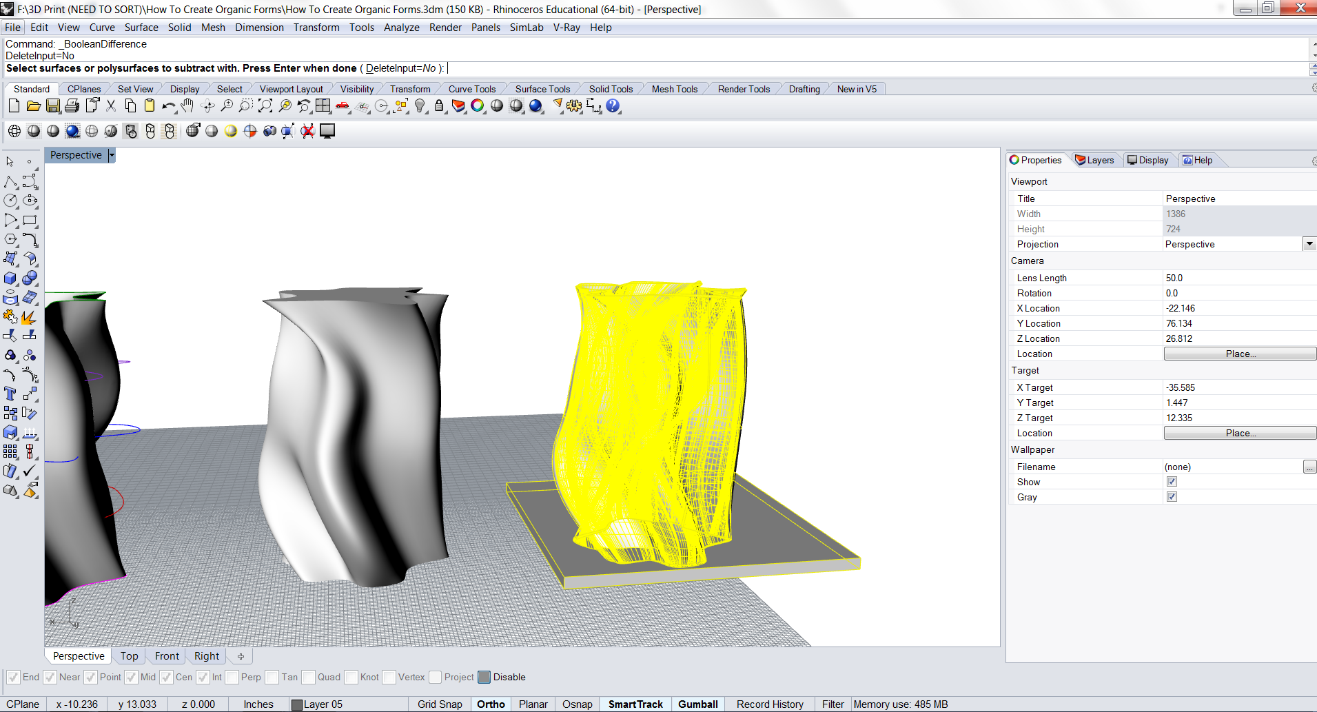
To create the base so that it is just on the interior of the Vase, we will have to Boolean Difference the box and delete the excess around the perimeter of the Vase.
Depending on the number of curves within the Vase and the complexity of the model, the tolerance may have to be increased for Rhino to process the Boolean Difference correctly.
Boolean Union
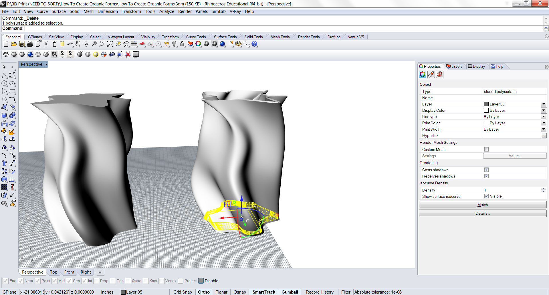
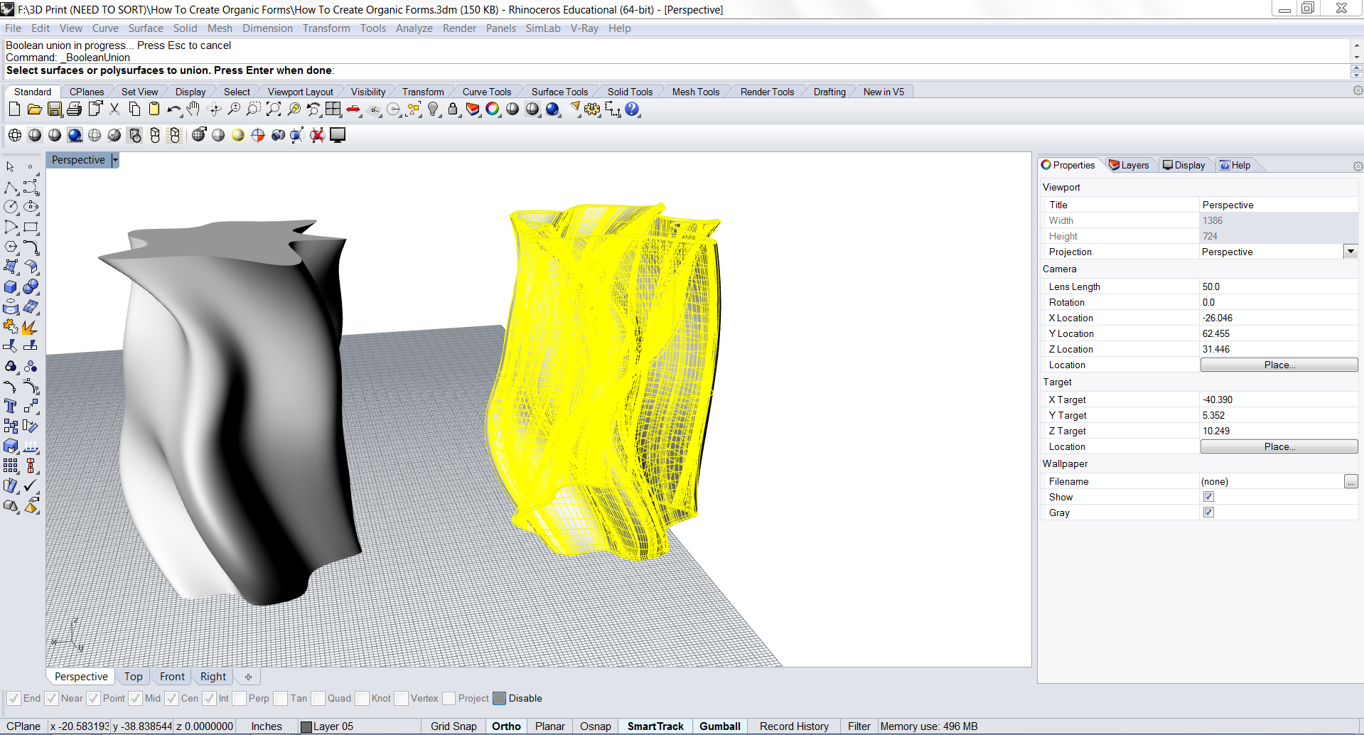
Select the newly created base and the Shell of the Vase and then Boolean Union the two objects to create one solid, closed polysurface.
Volume Check
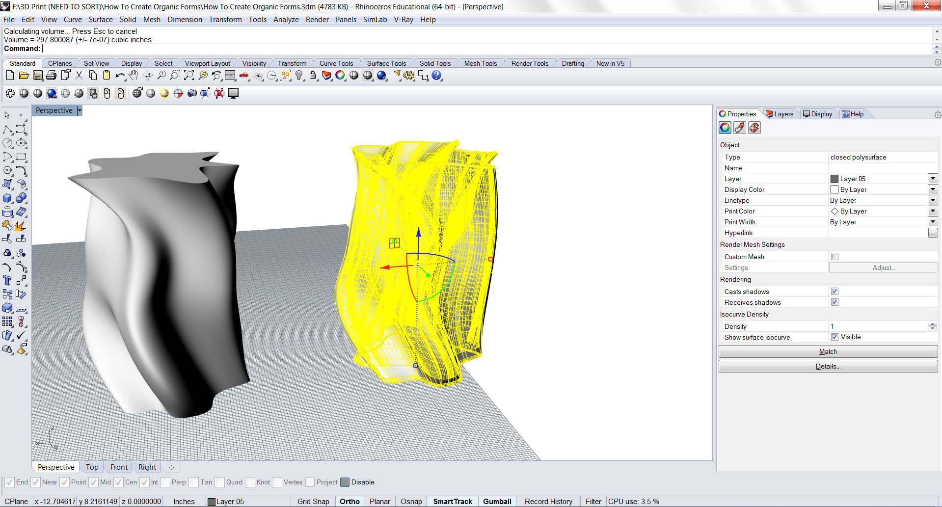
After the two polysurfaces are joined together to make one closed polysurface, we can check the Volume one last time before we export to STL File.
Export to STL and 3D Print!
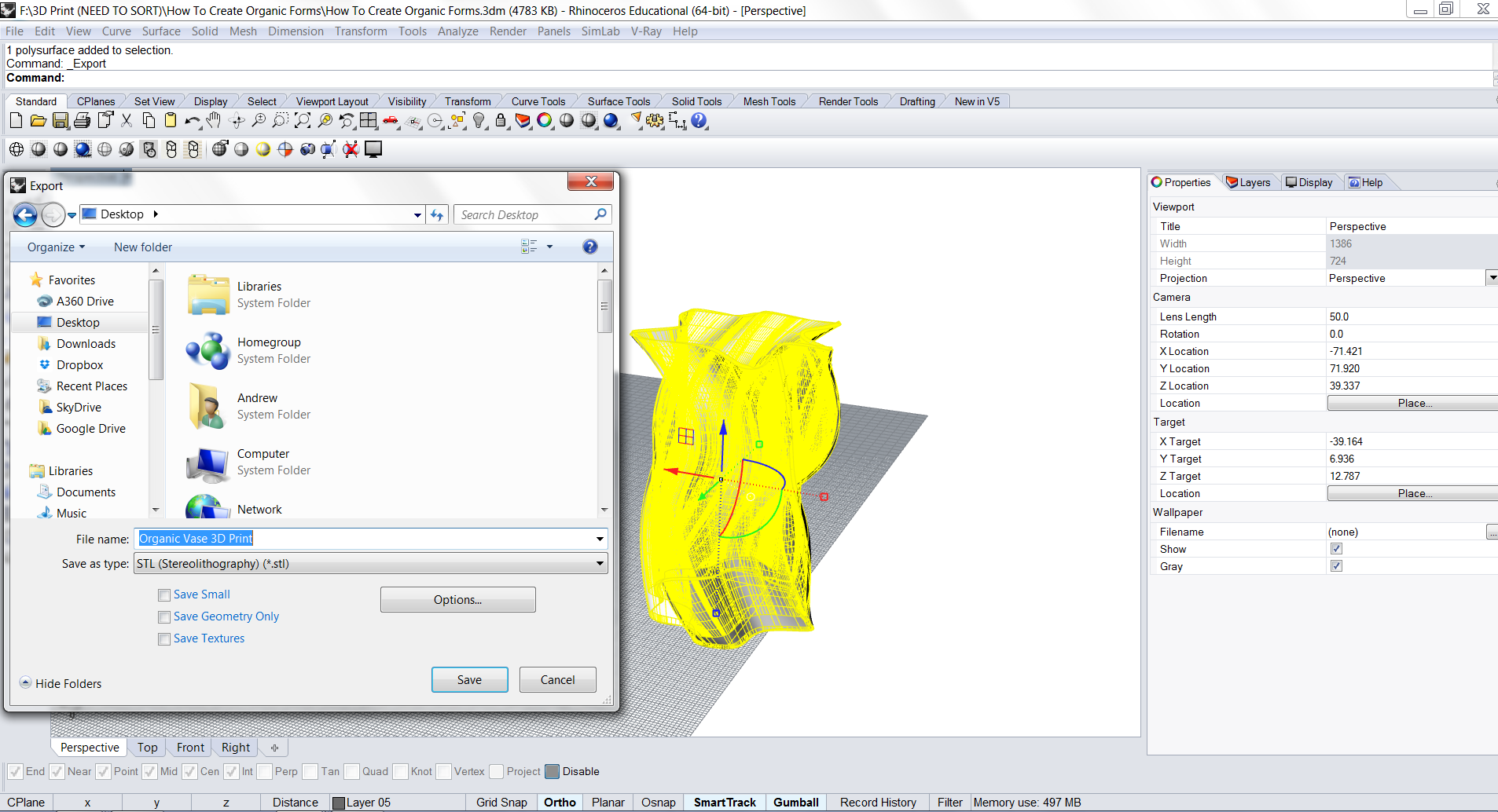
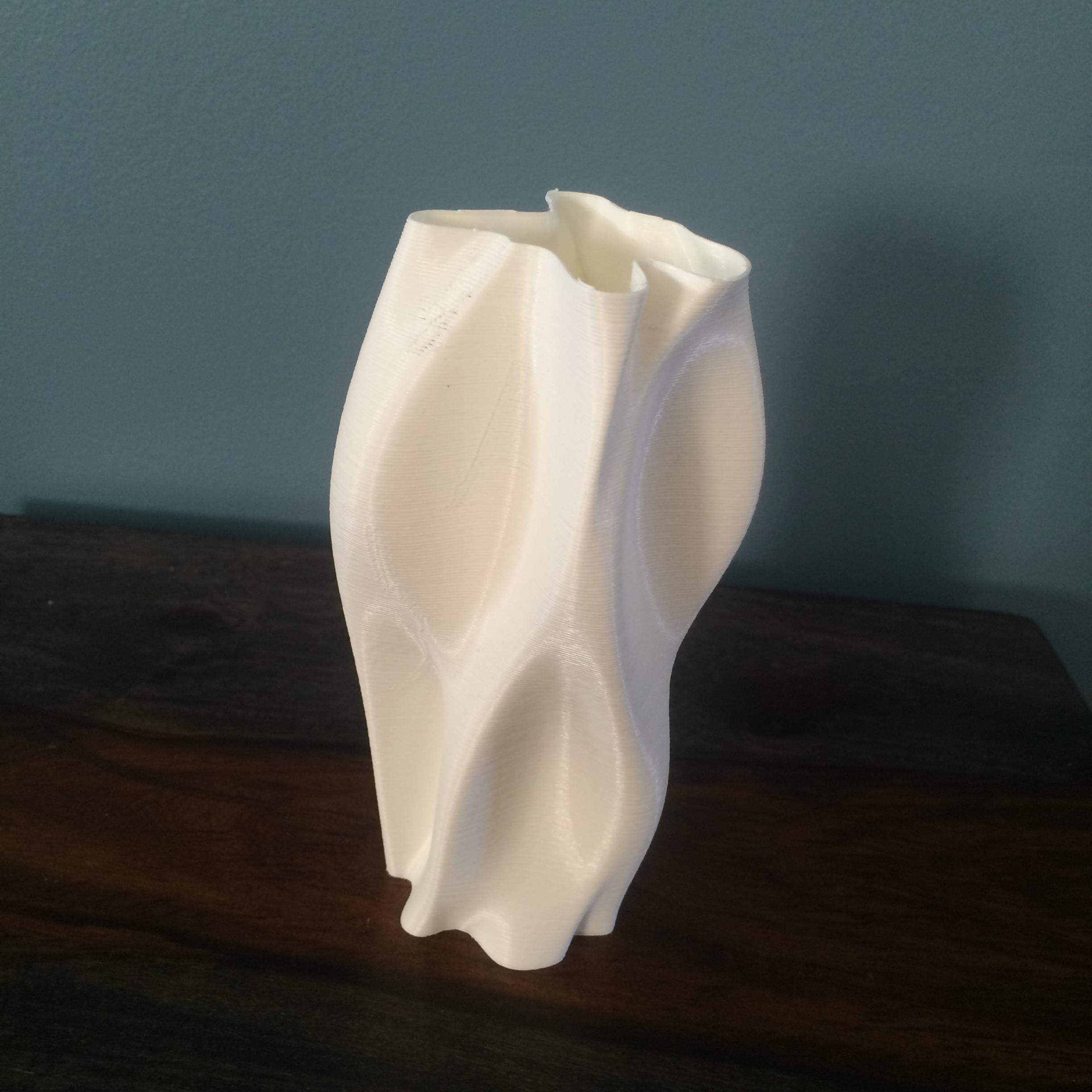
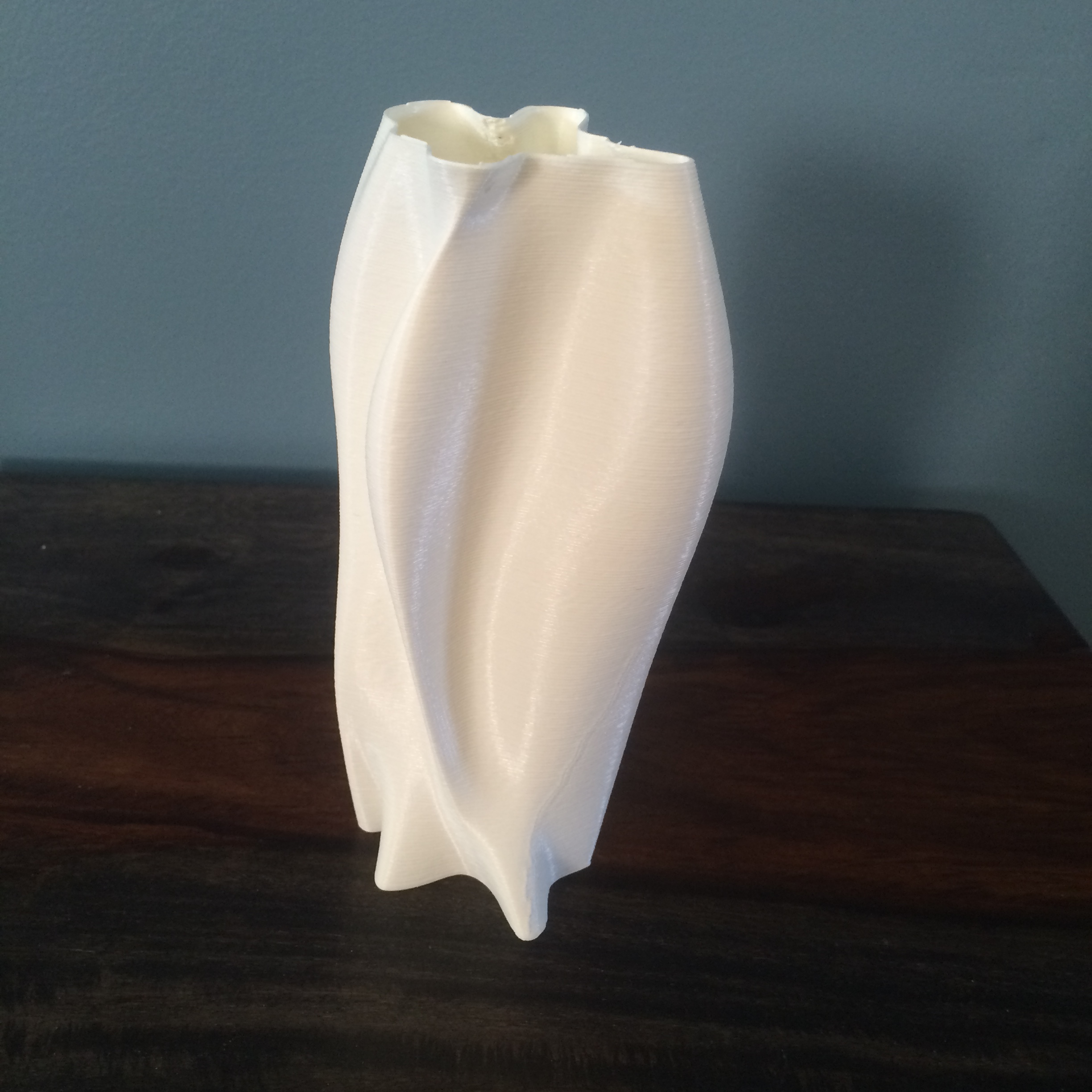
Once we verify that the Volume Command works correctly and we have a solid object, we can export to STL.
Simply save the STL and send to your 3D Printer!
Thank you for reading the Instructable! Enjoy!