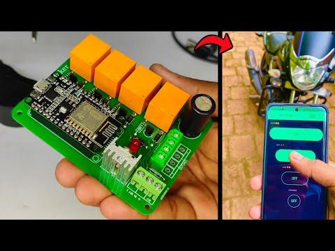
How to Control Bike/Scooty Using Your Smartphone
by Pro Maker_101 in Circuits > Wireless
588 Views, 1 Favorites, 0 Comments
How to Control Bike/Scooty Using Your Smartphone
.png)
Hey guys!! How are you ? I am going to do here today is how to control our bike using a smartphone.
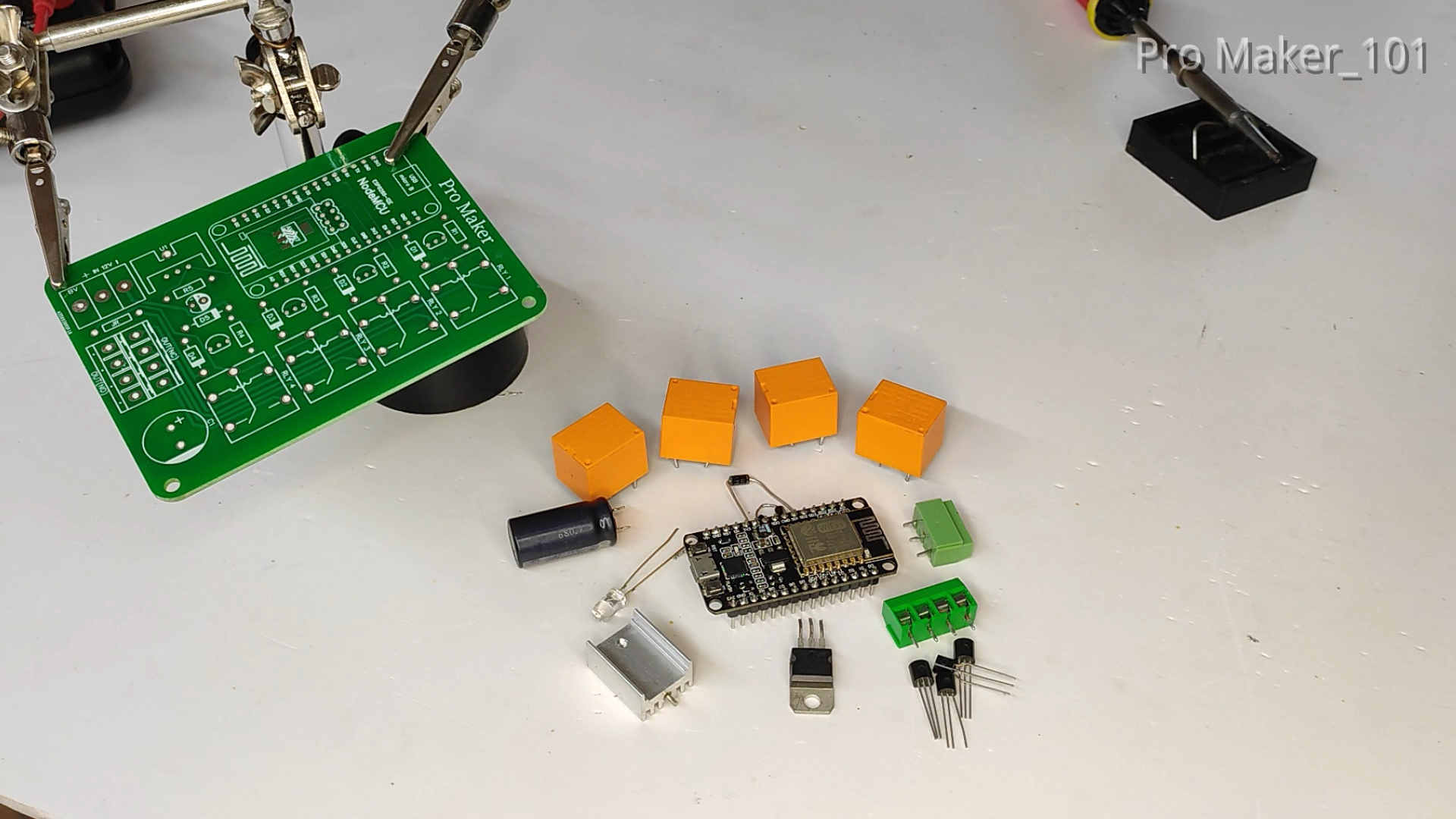
COMPONENTS REQUIRED
.png)
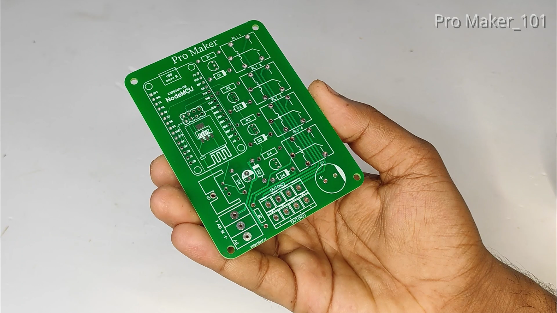
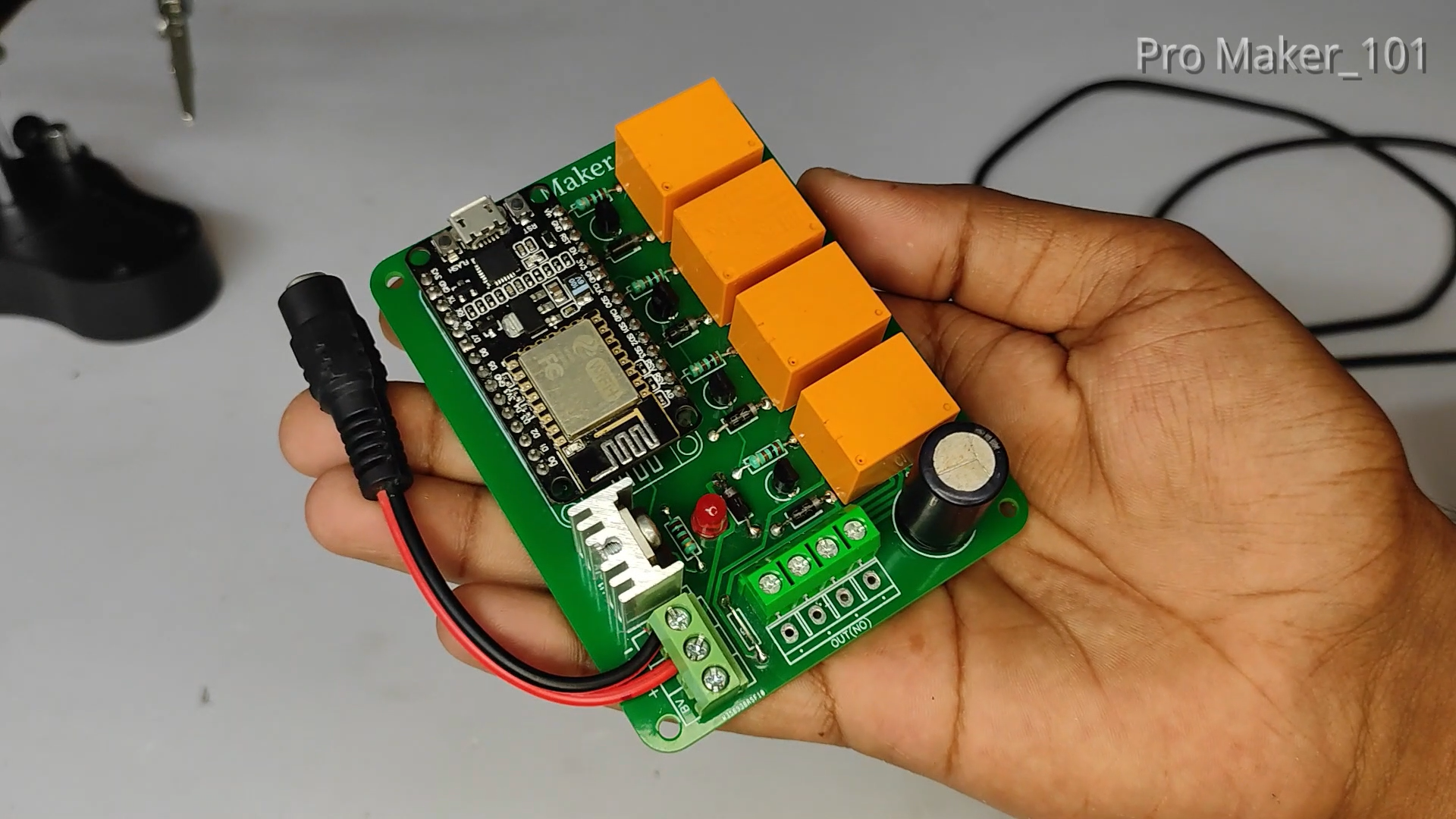
- PCB
- ESP8266-12E Module ( NodeMCU)
- 12v Relay - 4Nos
- 7805 regulator IC With Heatsink
- 2200uF/25V Capacitor
- BC547 Transistor - 4Nos
- 1K Resistor - 5Nos
- IN4007 Diode - 5Nos
- LED (Red)
- 3 Pin Screw Connector
- 4 Pin Screw Connector
- Female Header Pins
TOOLS NEEDED
- Soldering Iron
- Soldering Wire
- Flux
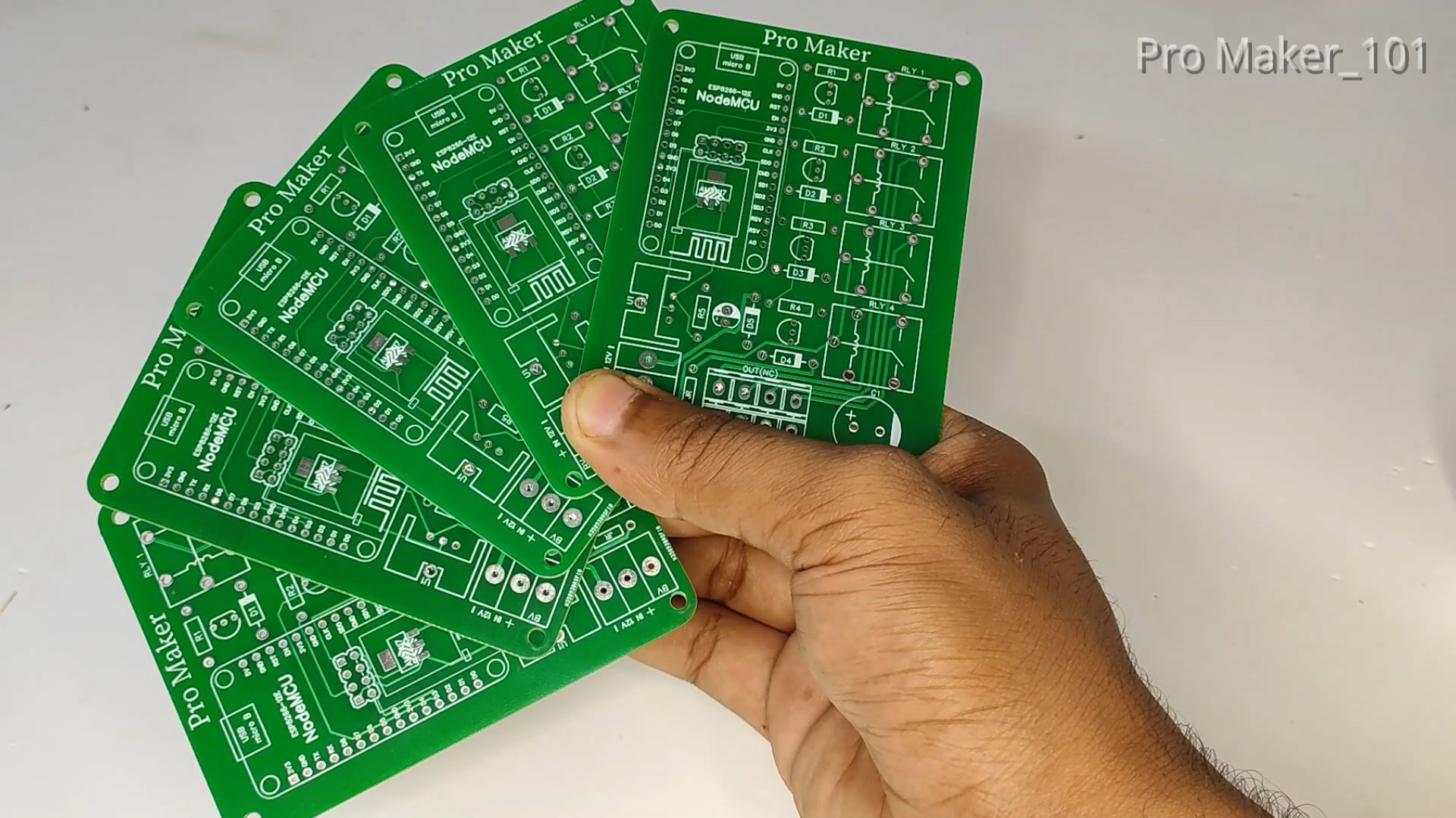
PCB
.png)
.png)
Therefore, case you want your own PCB, you can obtain through this link on PCBWay.com. You can also order good quality PCBS from PCBWay.com at low cost. In addition to the standard pcbs, we could also support advanced Pcbs, FPC/rigid -flex Pcbs, rapid-rpototyping and other related services that could meet your needs to the most extent.
PCB order steps on PCBWay:
- Visit the website: www.pcbway.com
- Click PCB Instant QuoteClick
- quick-order PCB Upload the gerber file by clicking "+Add Gerber File" and wait until the gerber file is finished
- uploading Set the PCB specifications as you wish, starting from the number of PCBs, the number of layers, thickness, color and others.
- After that, look at the left, it will display the estimated cost
- processing time and delivery service selected
-
Click Save to cart
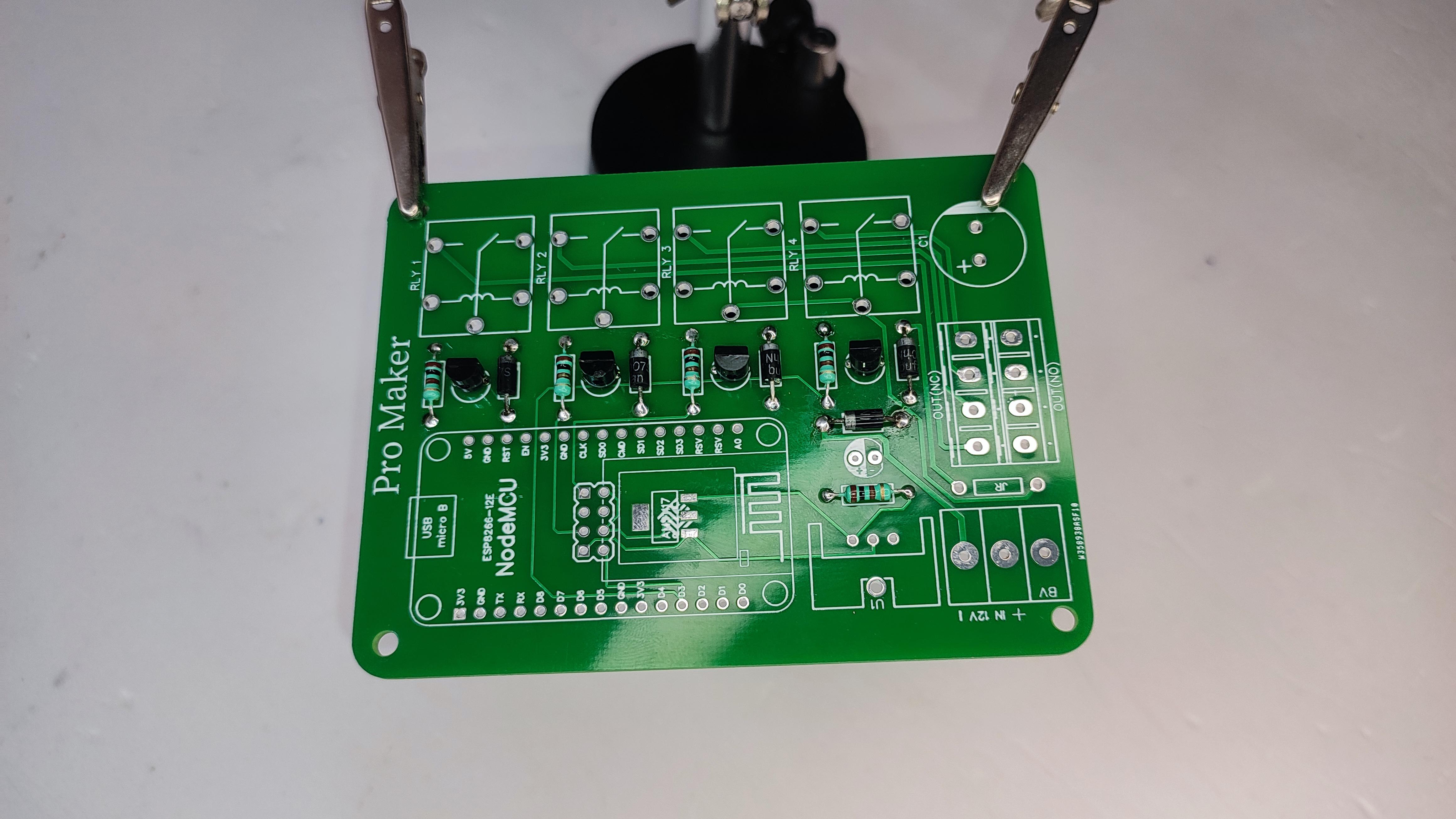
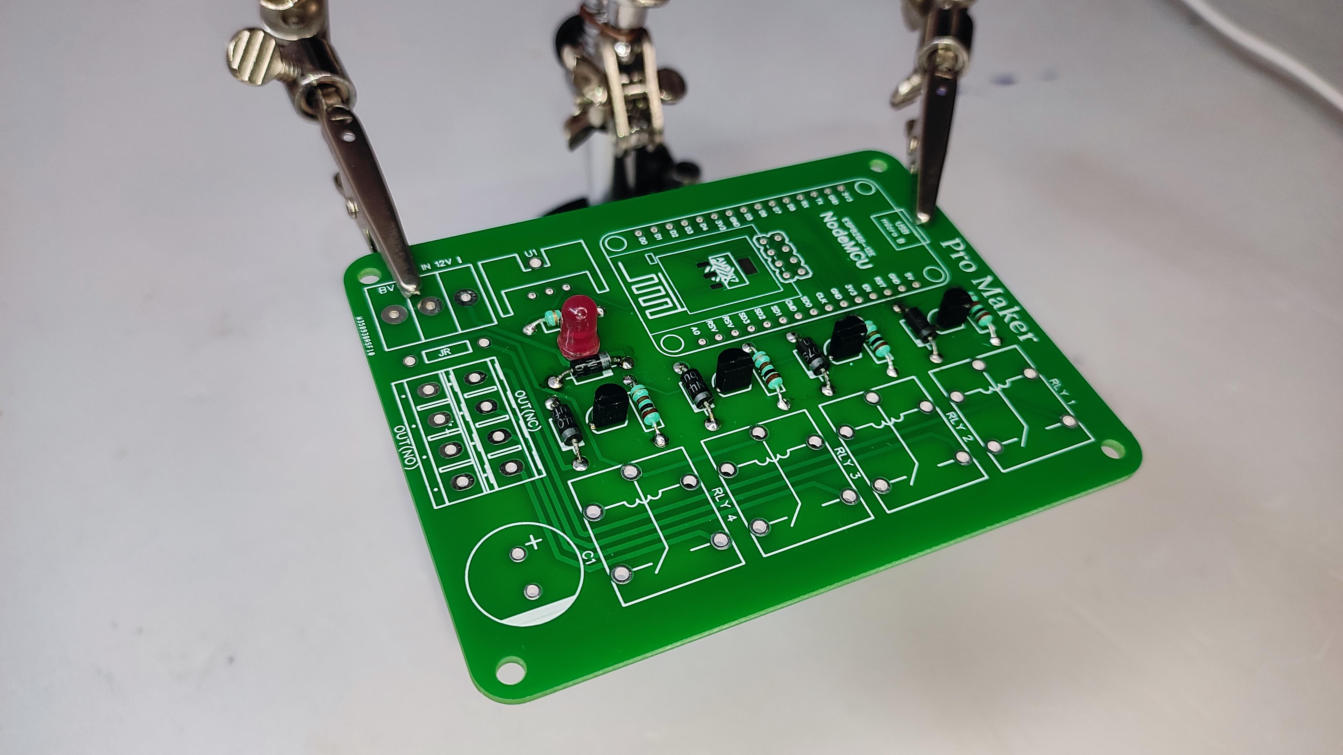
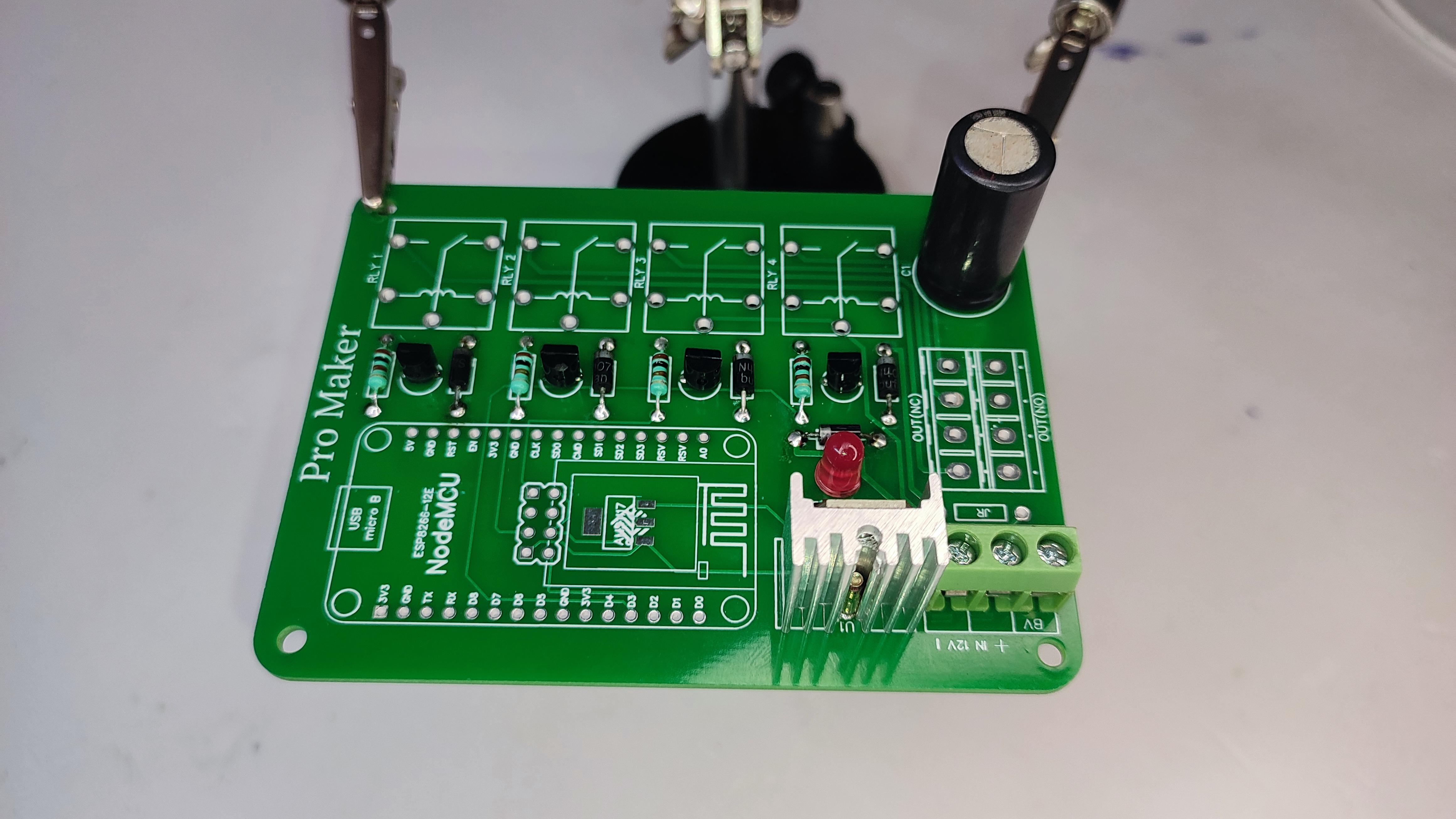
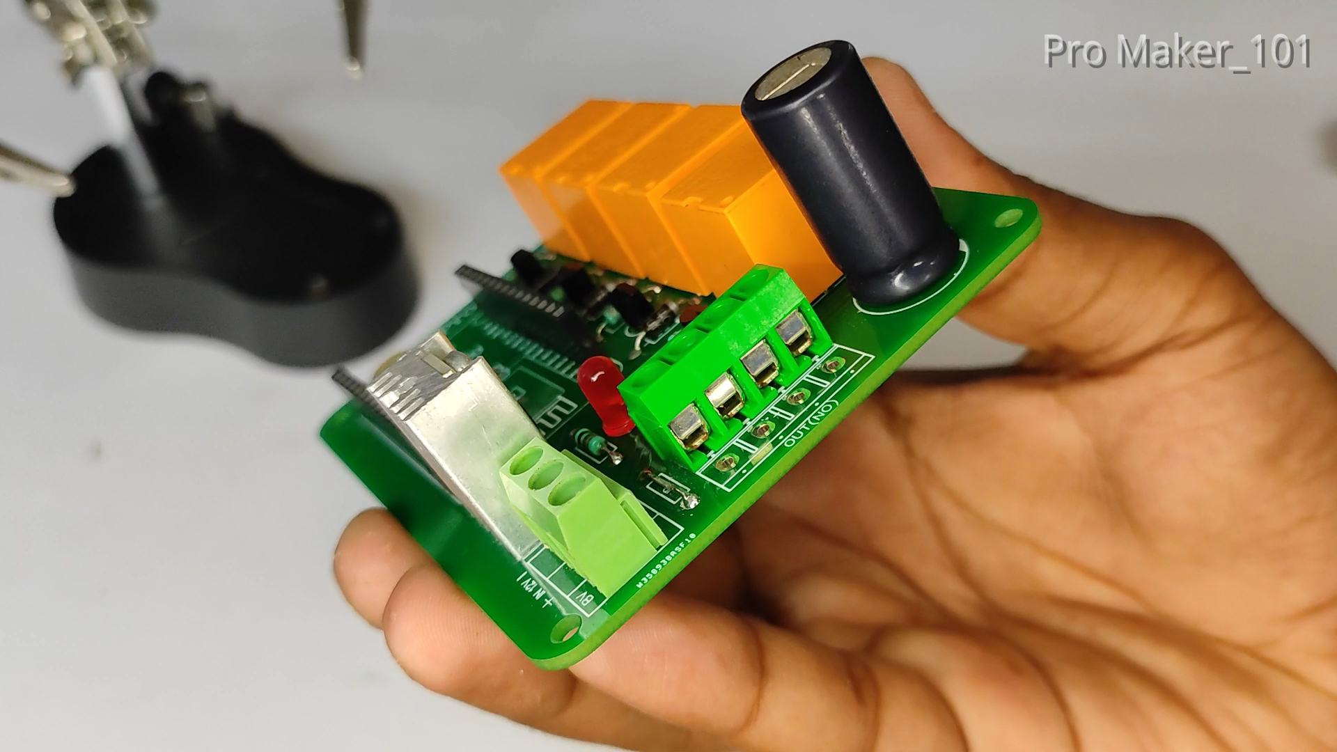
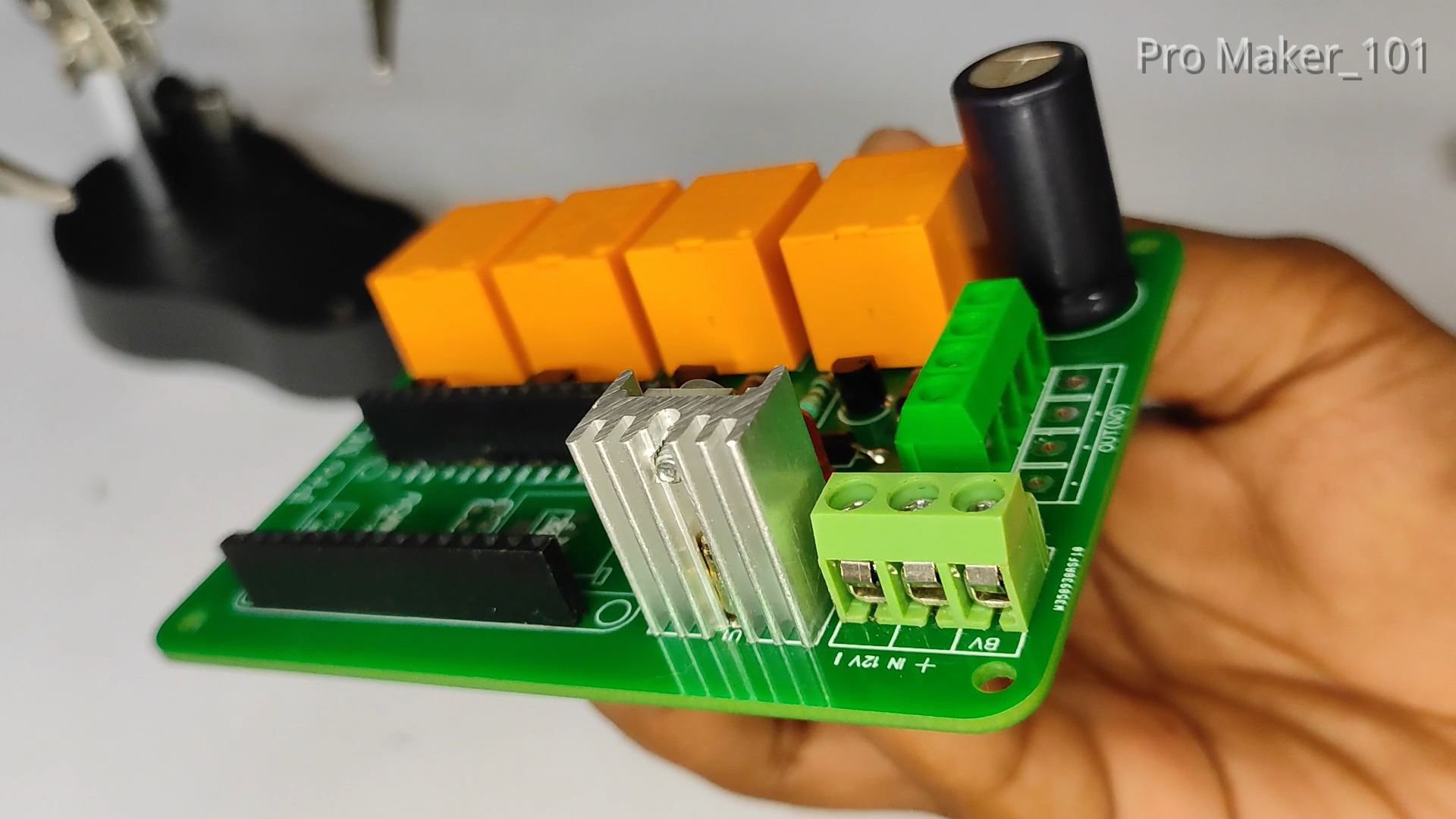
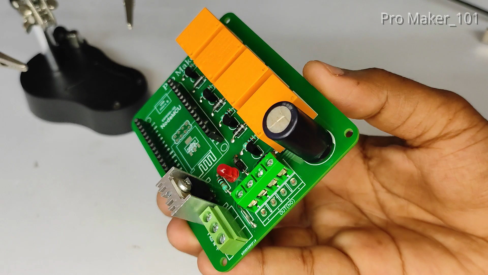
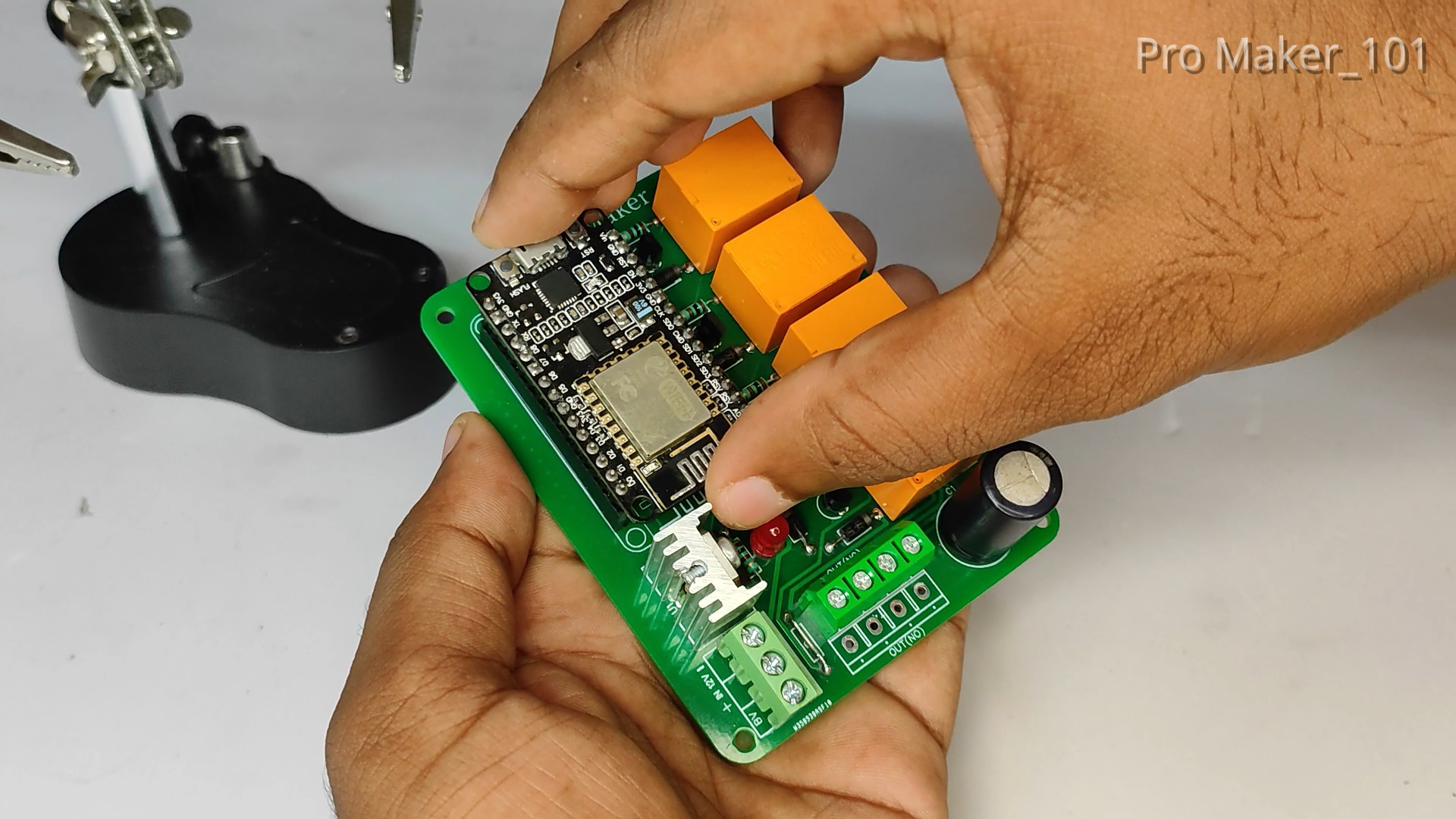
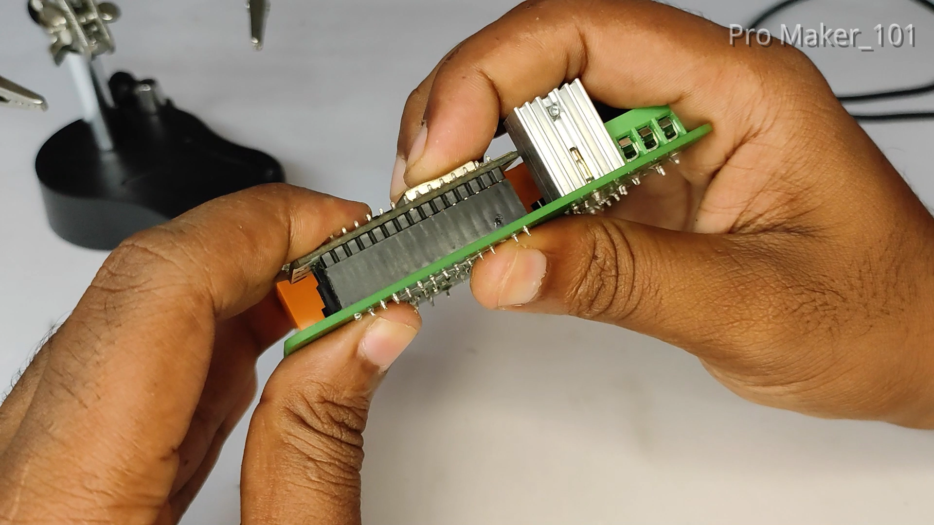
ASSEMBLING COMPONENTS ON PCB
.png)
.png)
.png)
.png)
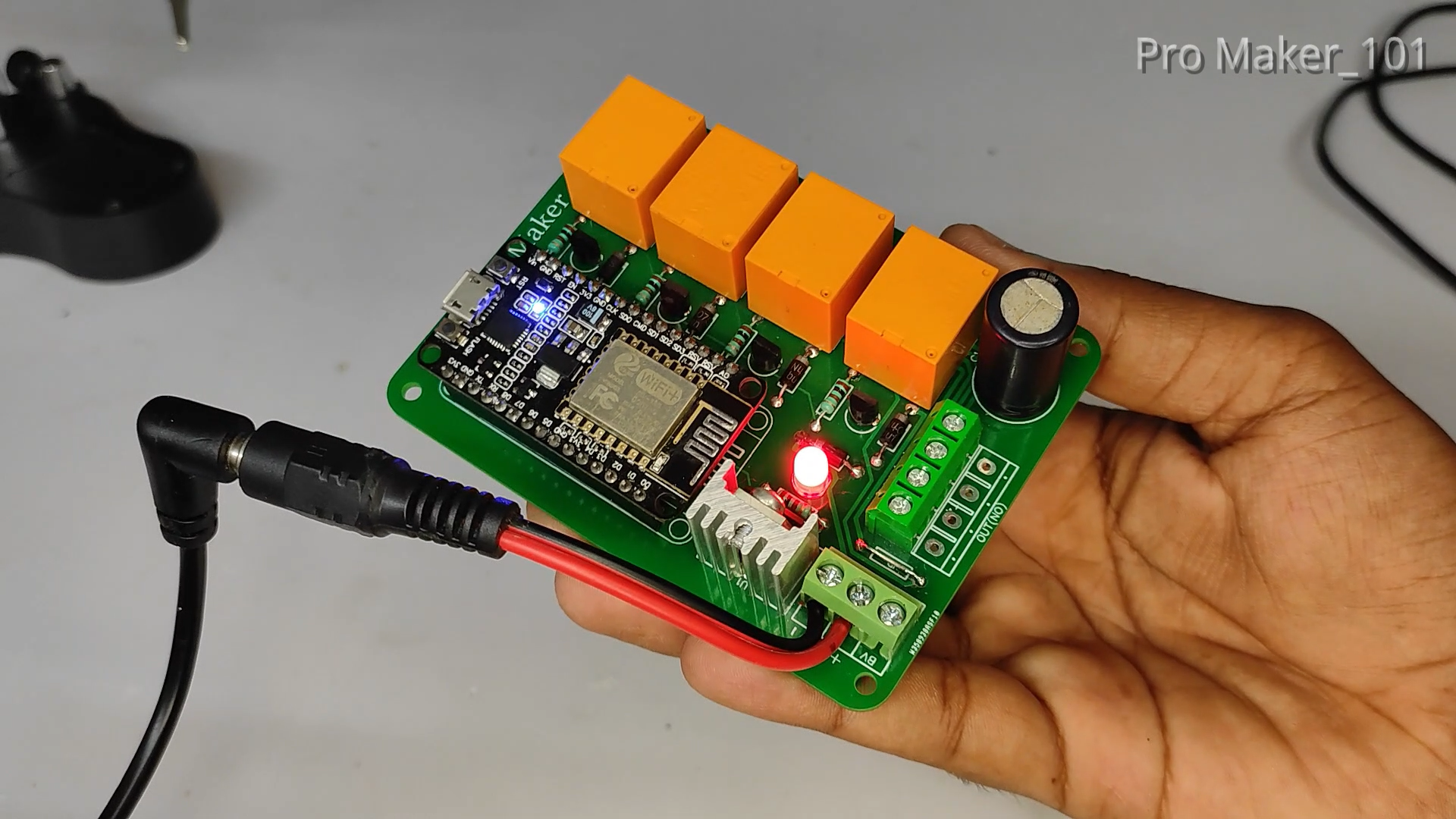
Connect the components to the PCB
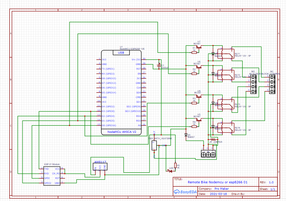
NodeMCU works at 5 volts and uses 7805 IC to convert 12 volts to 5 volts. A LED is given for the indication. capacitor is provided to get the proper output..
SCHEMATIC DIAGRAM
.png)
UPLOAD CODE ON NodeMCU
.png)
.png)
.png)
.png)
.png)
.png)
.png)
.png)
.png)
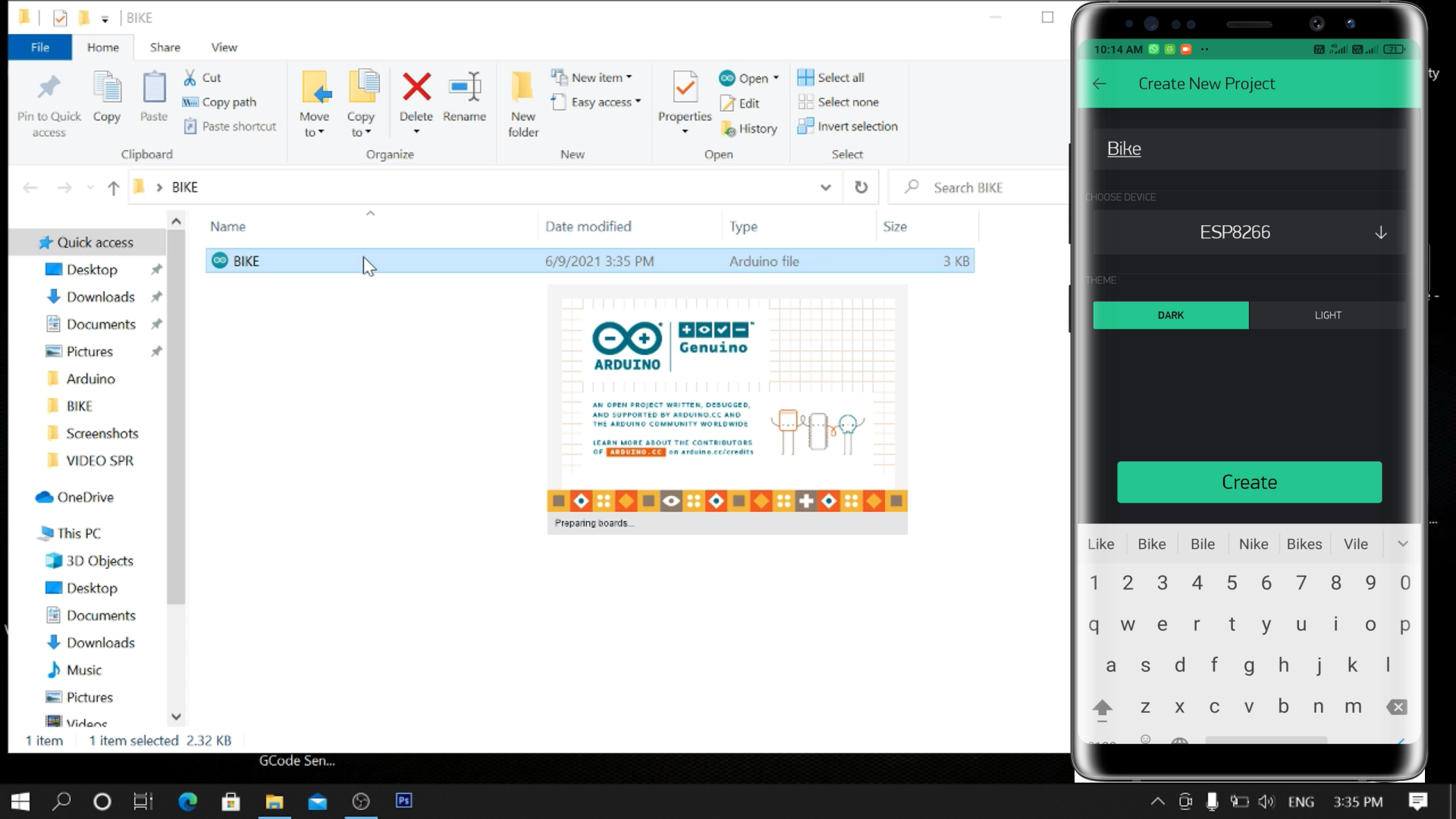
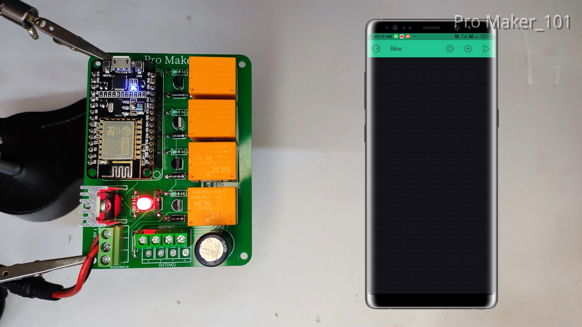
First Install Blynk app and create an account
- Click "New Project"
- Enter Project Name
- In the "CHOOSE DEVICE" section, select ESP8266
- Click on the "Create" button
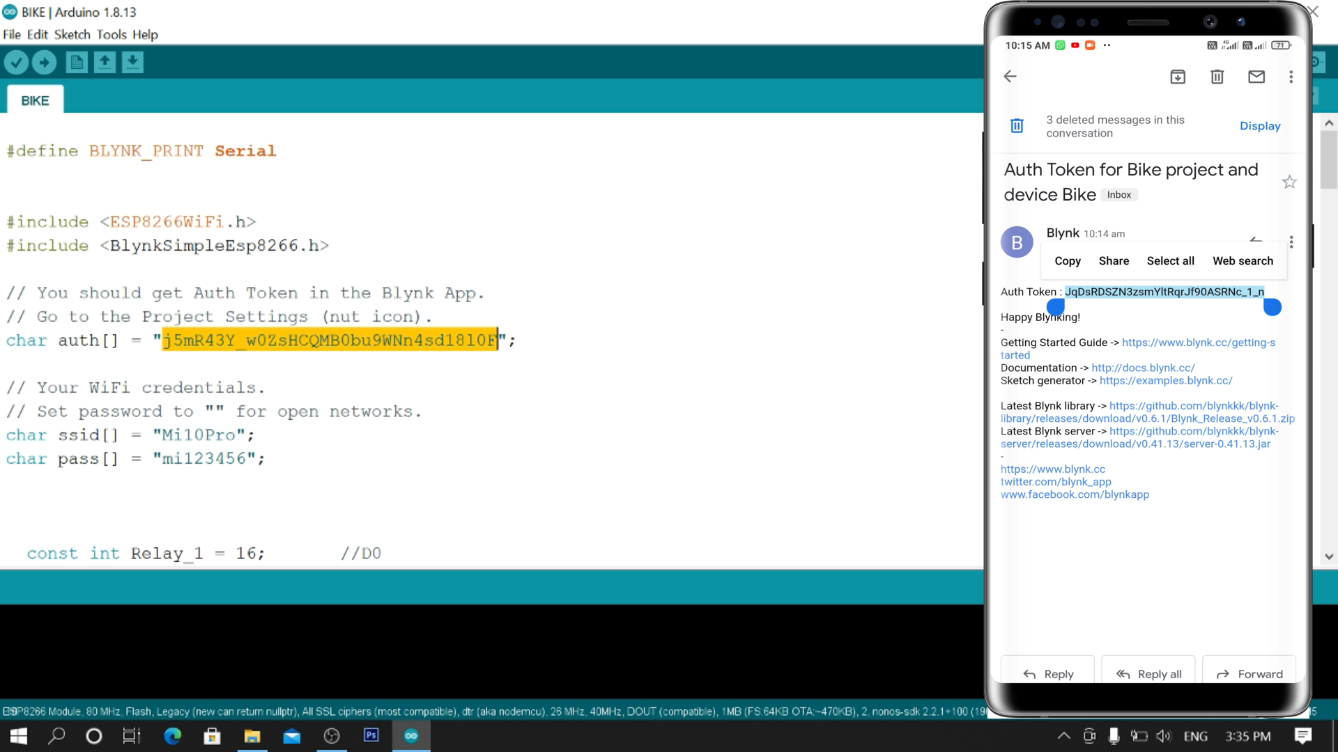
- After that Blynk will send an Auth Token to the registered email id. The Auth Token will be required while programming the ESP8266.Copy it..
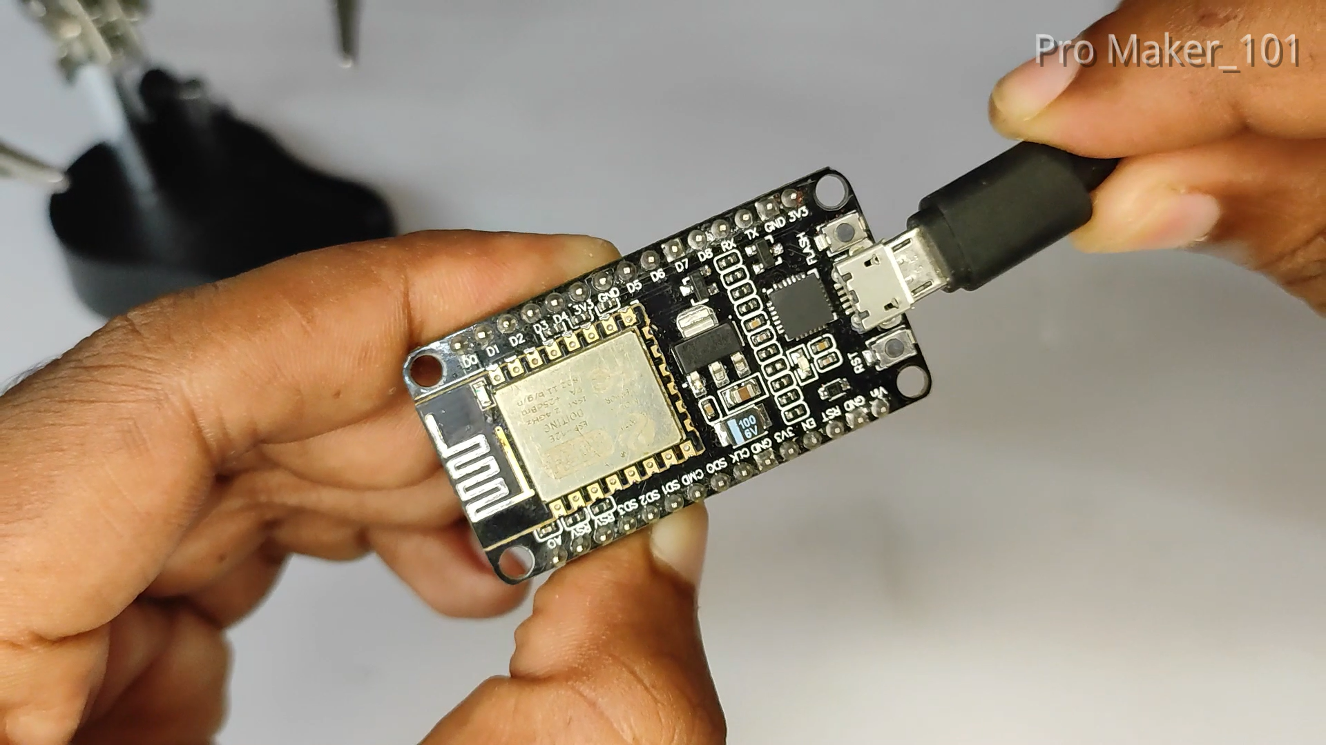
Connect NodeMCU on PC
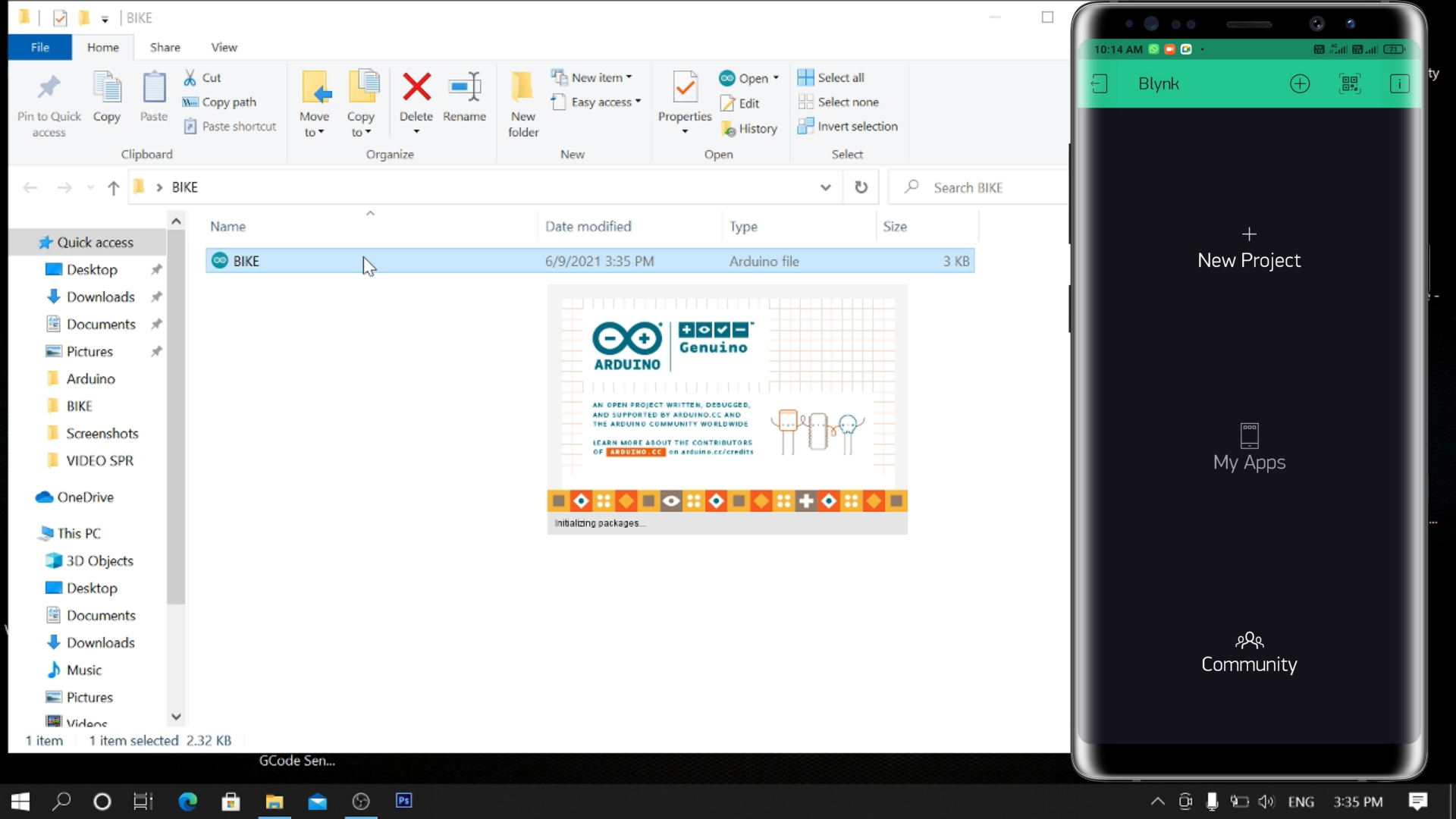
- Open Arduino IDE (Software)
- First update the Preferences –> Aditional boards Manager URLs: http://arduino.esp8266.com/stable/package_esp8266...
- Then install the ESP8266 board from the Board manager or Click Here to download ESP8266 Board.
- After that install the Blynk library. Click Here to download the Blynk library.
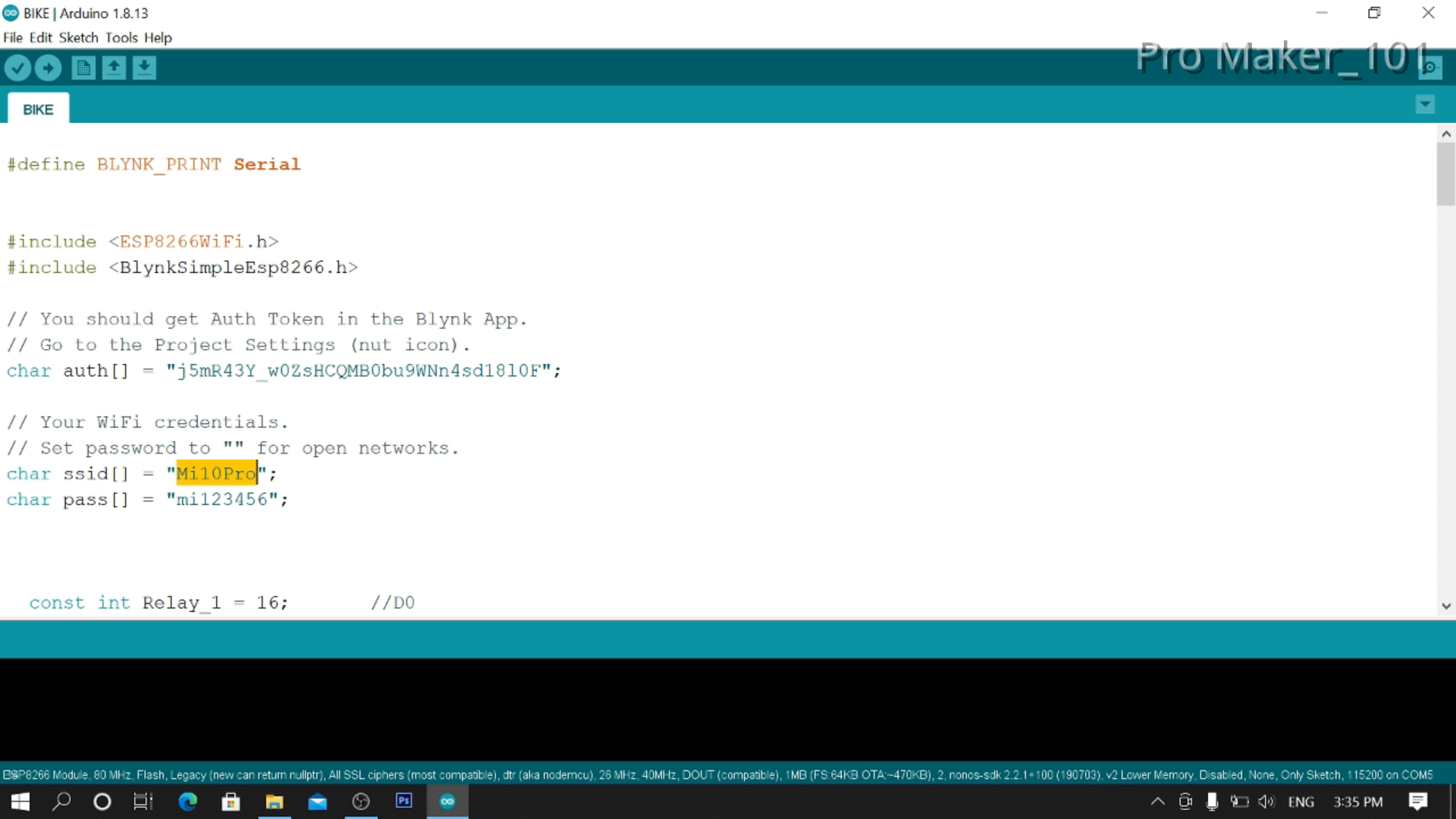
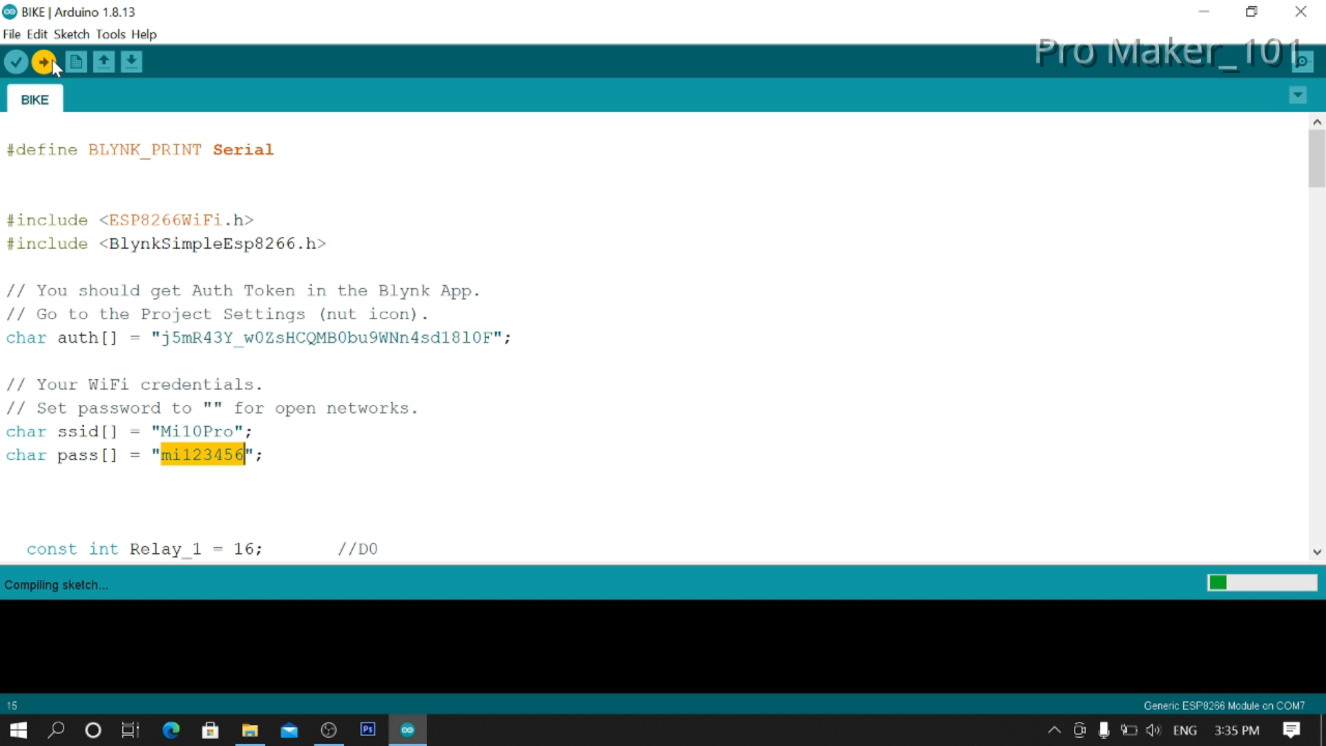
- Open BIKE.ino
- Enter AUTH TOKEN,SSID&PASSWORD(The ssid and password given in the code should be that of your hostspot)
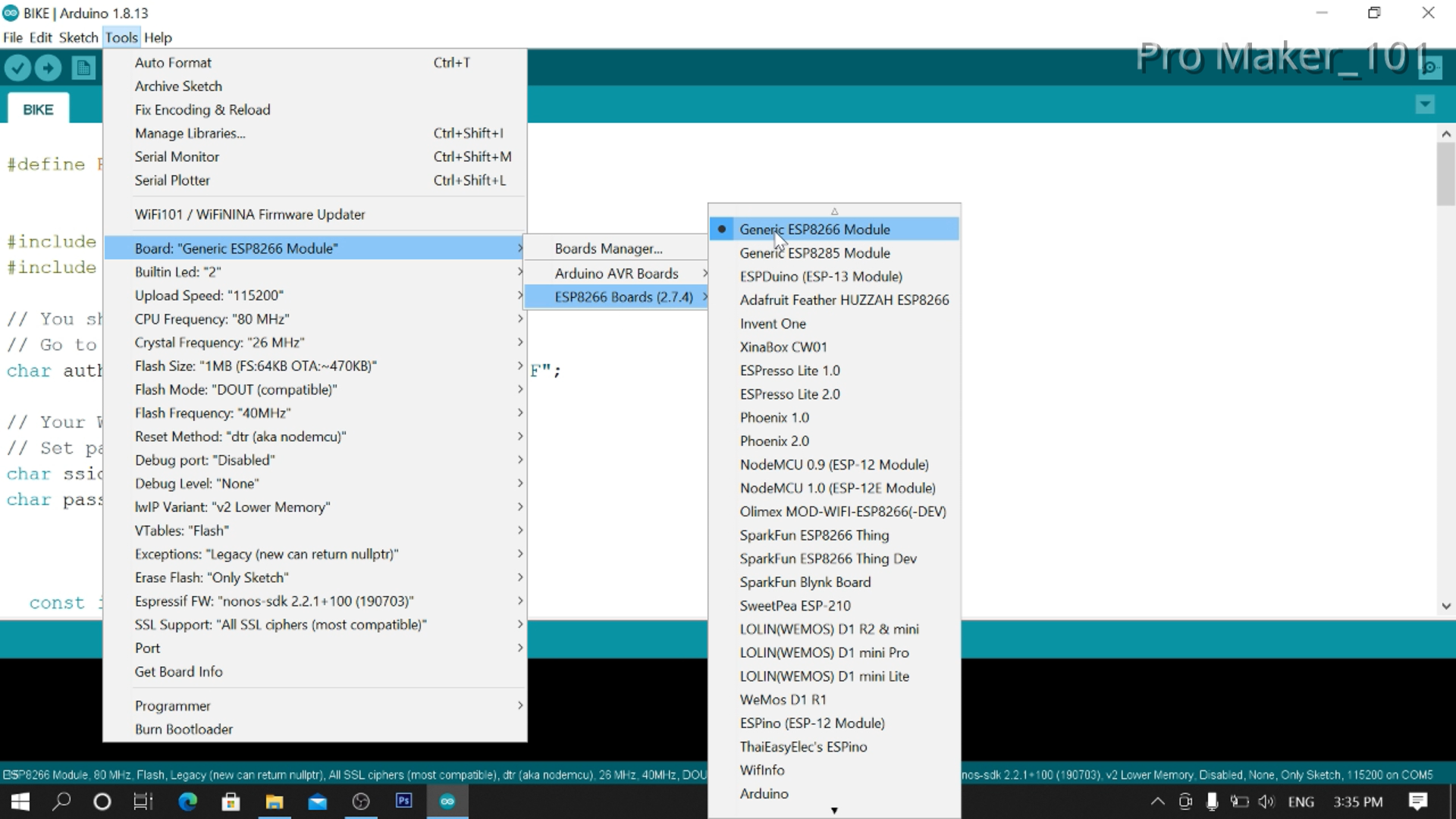
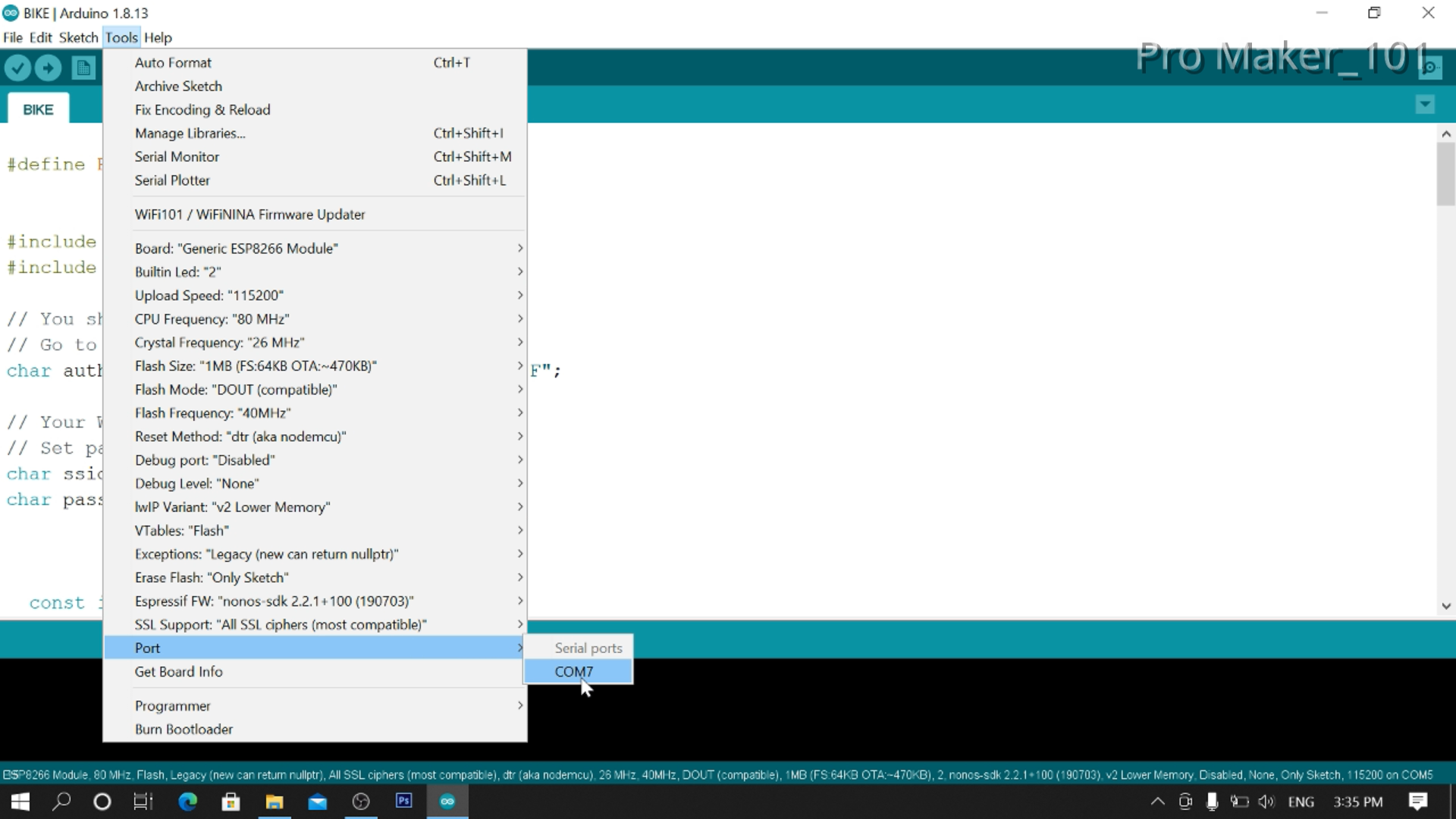
- Then Go To Tools>Board>ESP8266 Boards> NodeMCU 1.0 (ESP-12E Module)
- Select Correct Port
- Upload...
If you have any doubts, watch this video (Click Here)
CODE
#define BLYNK_PRINT Serial


#include <ESP8266WiFi.h>
#include <BlynkSimpleEsp8266.h>

// You should get Auth Token in the Blynk App.
// Go to the Project Settings (nut icon).
char auth[] = "AUTH TOKEN";

// Your WiFi credentials.
// Set password to "" for open networks.
char ssid[] = "HOTSPOT SSID";
char pass[] = "HOTSPOT PASSWORD";


  const int Relay_1 = 16;       //D0
  const int Relay_2 = 5;        //D1
  const int Relay_3 = 4;        //D2
  const int Relay_4 = 0;        //D3


void setup()
{
  pinMode(Relay_1, OUTPUT);
  pinMode(Relay_2, OUTPUT);
  pinMode(Relay_3, OUTPUT);
  pinMode(Relay_4, OUTPUT);


    digitalWrite(Relay_1, LOW);
    digitalWrite(Relay_2, LOW);
    digitalWrite(Relay_3, LOW);
    digitalWrite(Relay_4, LOW);


  // Debug console
  Serial.begin(115200);
  Blynk.begin(auth, ssid, pass);


}

void loop()
{
  Blynk.run();
}


/********************** Relay 1  ON/OFF V1 *******************************/
BLYNK_WRITE(V1)
  {
  int pinValue = param.asInt();
  if (pinValue == 1)
    {
    digitalWrite(Relay_1, HIGH);
    Serial.println("Relay 1 On");
    }
  else if (pinValue == 0)
    {
    digitalWrite(Relay_1, LOW);
    Serial.println("Relay 1 Off");
    }
  }


/********************** Relay 2  ON/OFF V2 *******************************/
BLYNK_WRITE(V2)
  {
  int pinValue = param.asInt();
  if (pinValue == 1)
    {
    digitalWrite(Relay_2, HIGH);
    Serial.println("Relay 2 On");
    }
  else if (pinValue == 0)
    {
    digitalWrite(Relay_2, LOW);
    Serial.println("Relay 2 Off");
    }
  }


/********************** Relay 3  ON/OFF V3 *******************************/
BLYNK_WRITE(V3)
  {
  int pinValue = param.asInt();
  if (pinValue == 1)
    {
    digitalWrite(Relay_3, HIGH);
    Serial.println("Relay 3 On");
    }
  else if (pinValue == 0)
    {
    digitalWrite(Relay_3, LOW);
    Serial.println("Relay 3 Off");
    }
  }


/********************** Relay 4  ON/OFF V4 *******************************/
BLYNK_WRITE(V4)
  {
  int pinValue = param.asInt();
  if (pinValue == 1)
    {
    digitalWrite(Relay_4, HIGH);
    Serial.println("Relay 4 On");
    }
  else if (pinValue == 0)
    {
    digitalWrite(Relay_4, LOW);
    Serial.println("Relay 4 Off");
    }
  }
Downloads
.png)
.png)
.png)
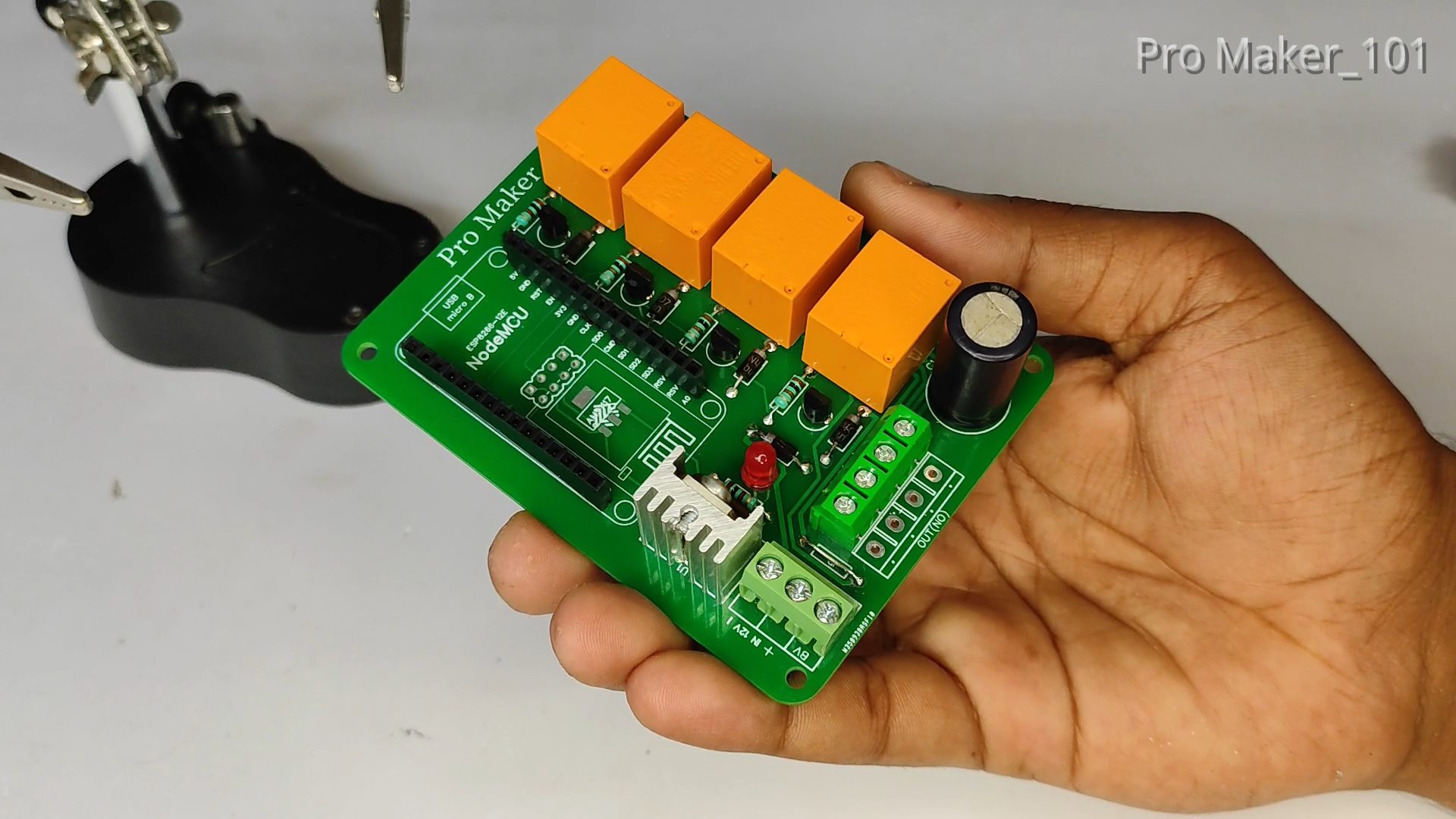
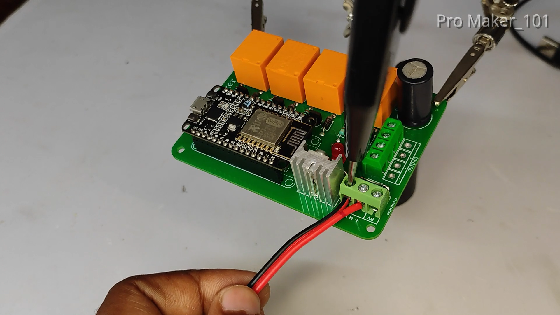
After uploading the code, set NodeMCU to PCB. With this, our PCB work is completed...
.png)
.png)
.png)
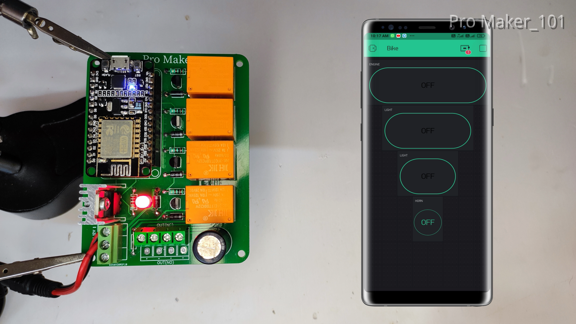
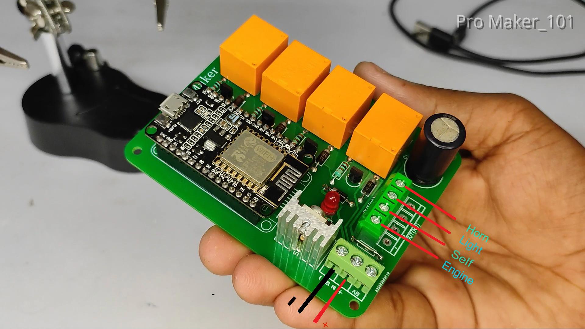
A 12v supply is provided for testing, and the connection to the battery must be made when placing the bike. Positive and negative are marked on the board.
ADDING BUTTONS IN BLYNK APP
.png)
.png)
.png)
.png)
.png)
.png)
.png)
.png)
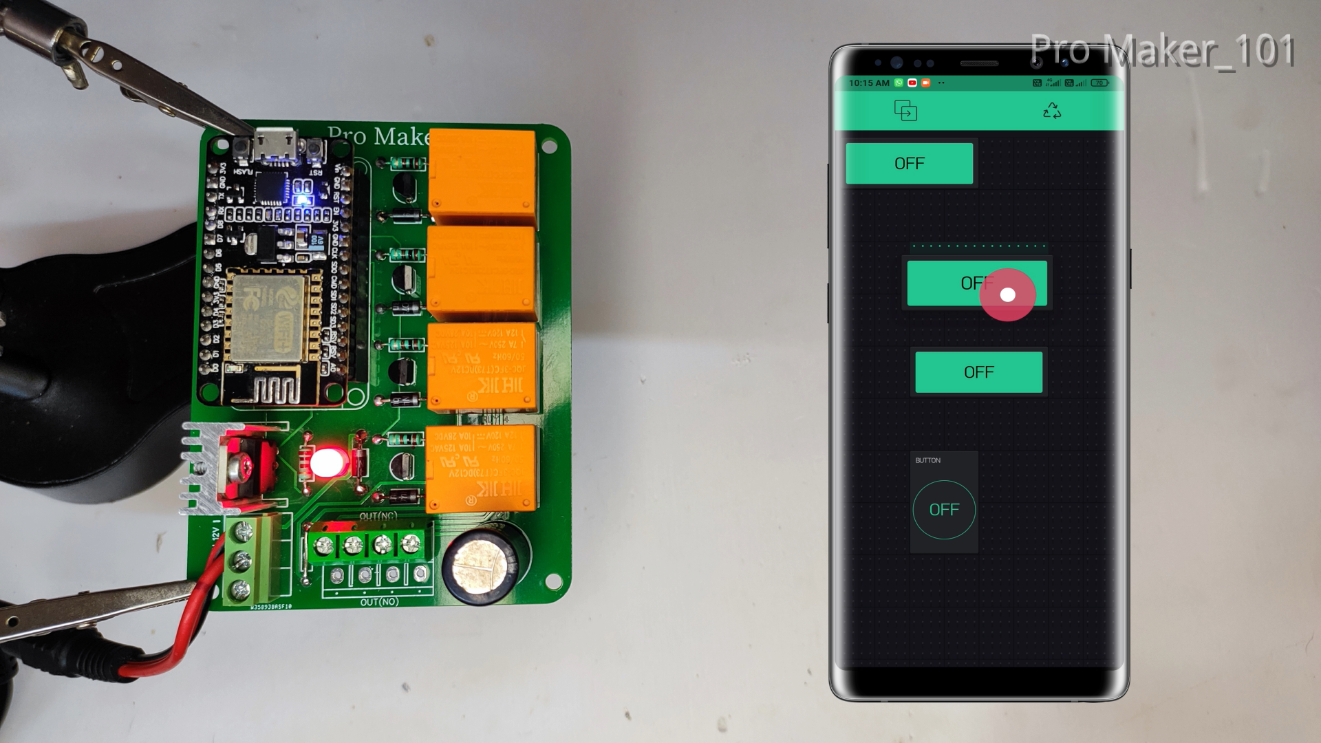
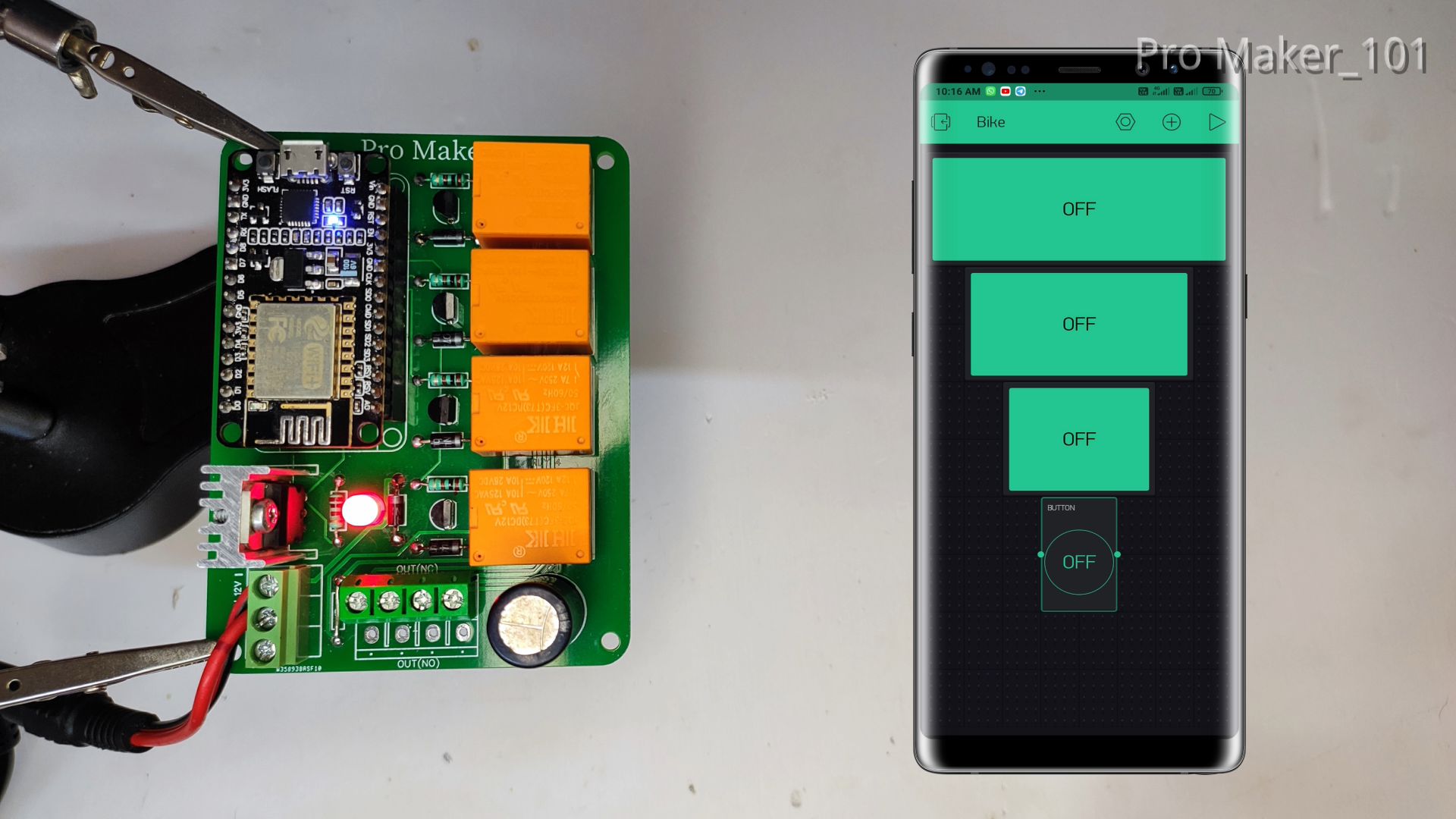
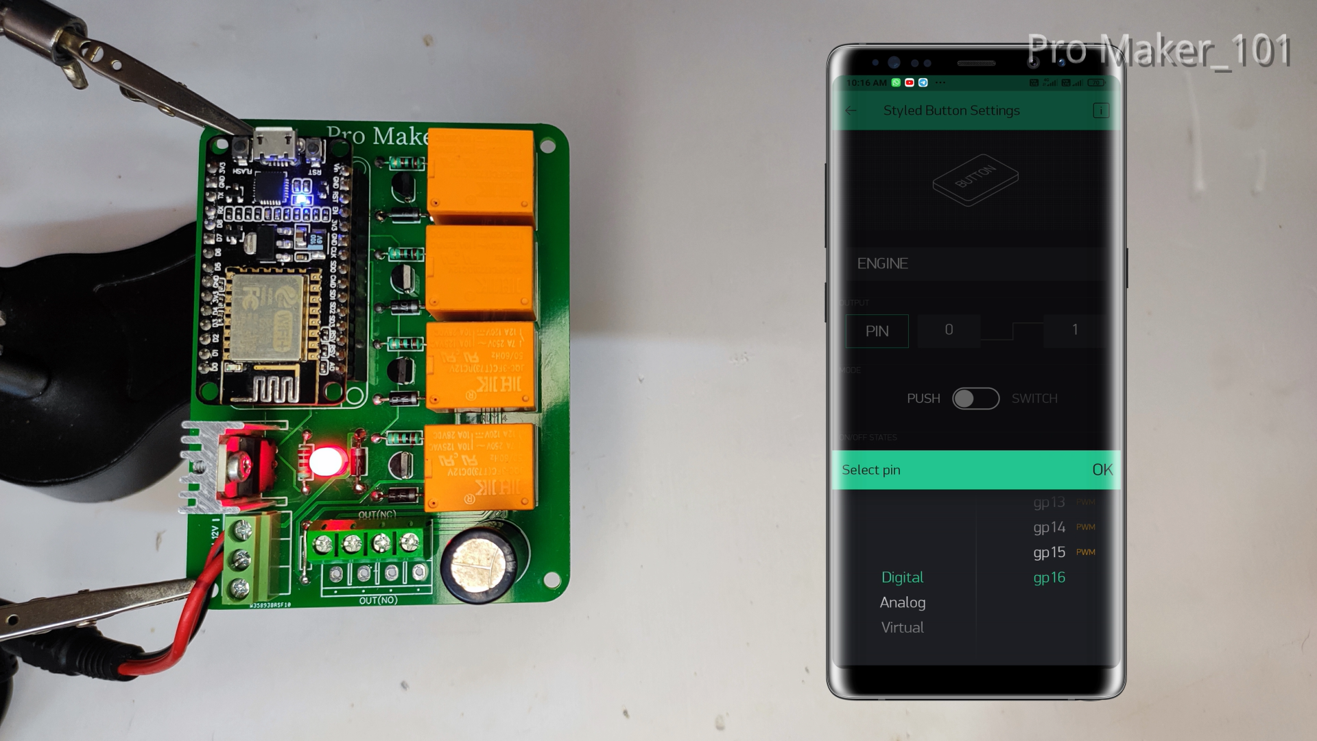
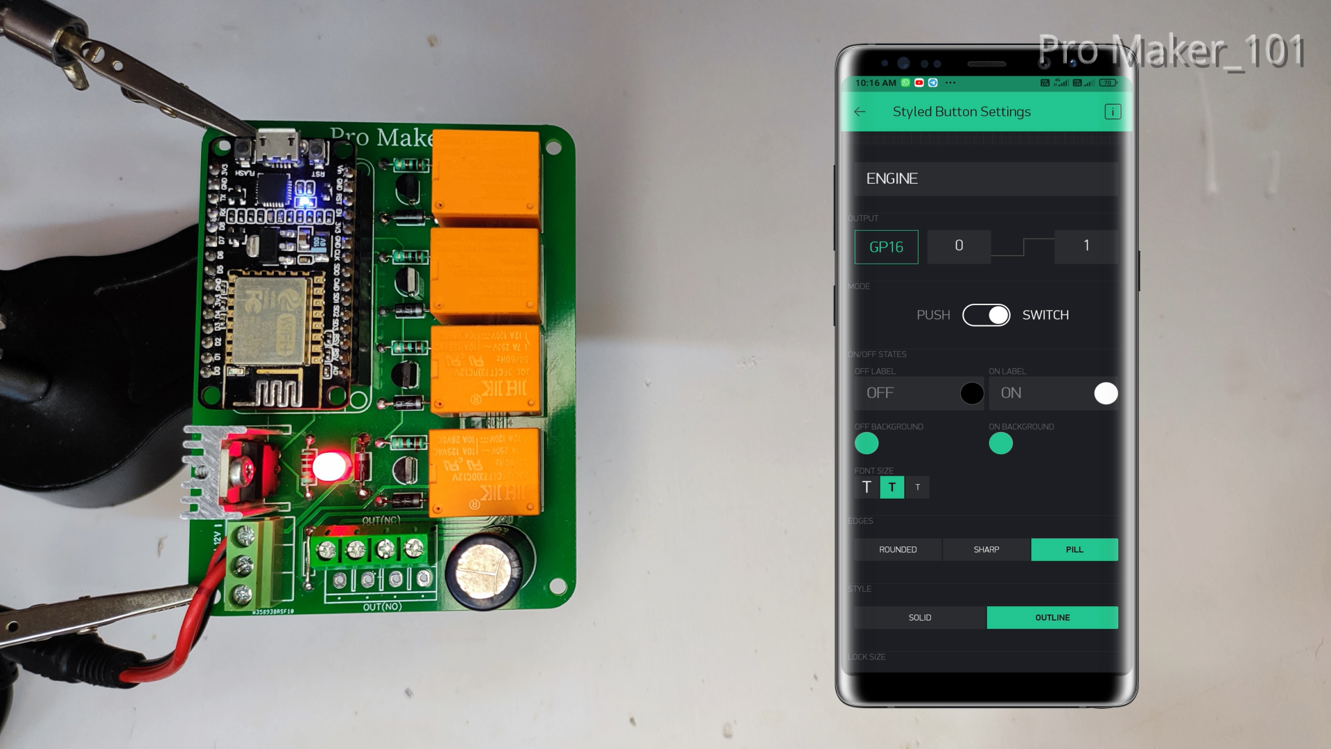
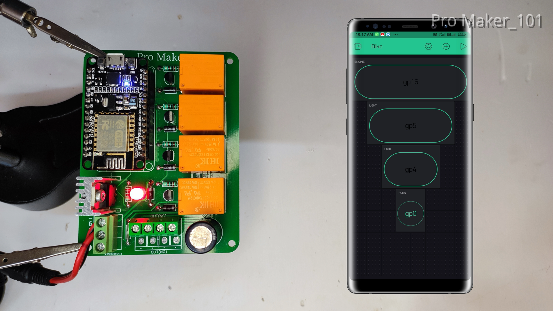
- Now you will get your dashboard screen. Just click on the the top most button "+" on the right corner to add widgets to your project (I have used 3 styled buttons and 1 round button here)
- Arrange All Buttons
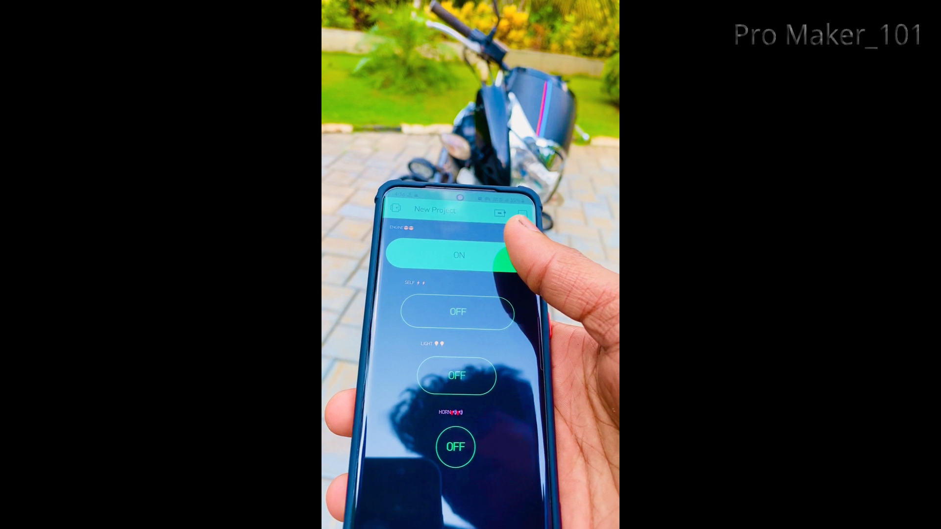
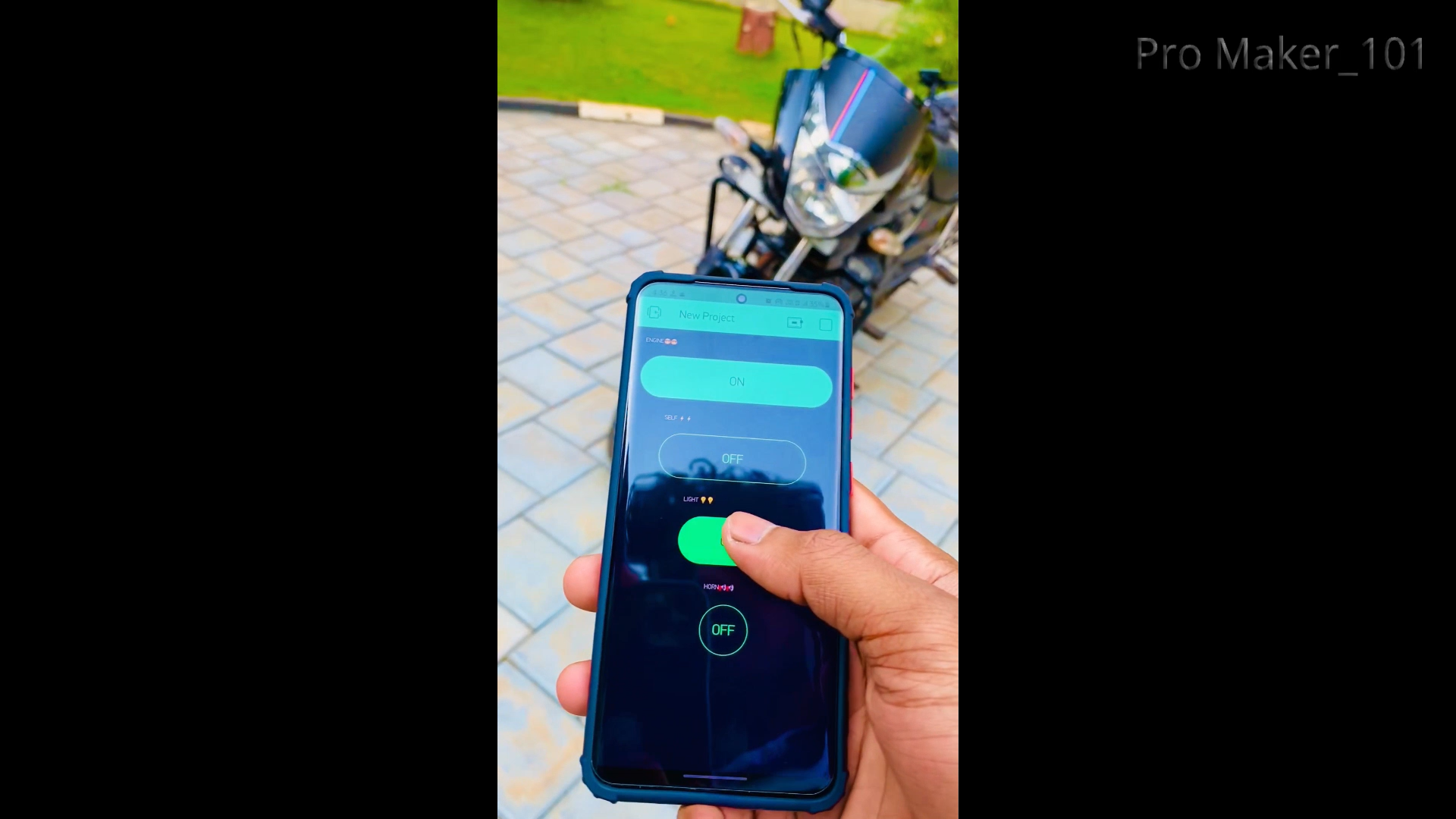
- Click 1st Button and select PIN =GP16 ,MODE = SWITCH , EDGE = PILL, STYLE = OUTLINE (Engine)
-
Click 2nd Button and select PIN =GP5 ,MODE = PUSH , EDGE = PILL, STYLE = OUTLINE (Self)
-
Click 3rd Button and select PIN =GP4 ,MODE = PUSH , EDGE = PILL, STYLE = OUTLINE (Light)
-
Click 4th Button and select PIN =GP0 ,MODE = PUSH , EDGE = PILL, STYLE = OUTLINE (Horn)
-
Turn on your Hotspot (The ssid and password given in the code should be that of your mobile hotspot)
-
Then click on the Play button in the top right corner of the Blynk app
If you have any doubts, watch this video (Click Here)
We can also do this project with local WiFi and I will do it later
CONNECTION DIAGRAM
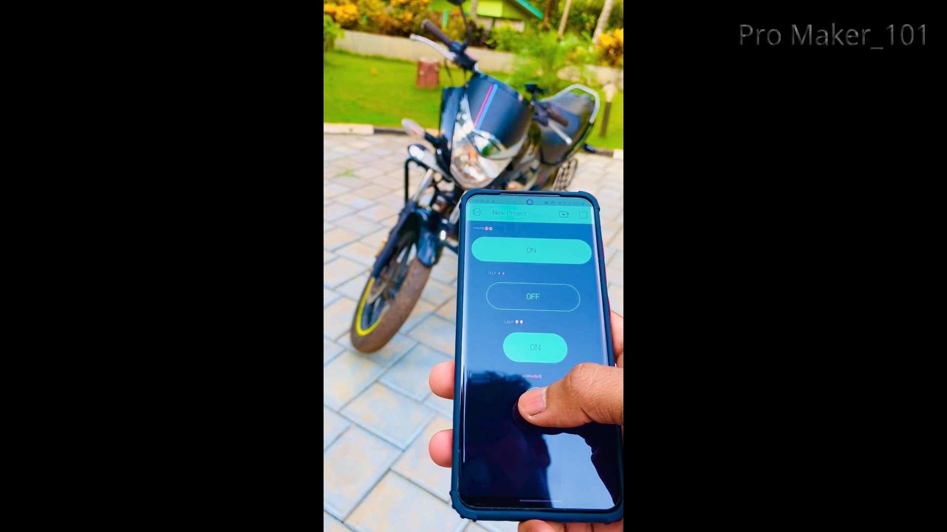
WORKING

.png)
.png)
Watch this video (Click Here)
THANKYOU....