How to Control 8 LEDs Module With MUX Breakout
by sfeelectronics in Circuits > Arduino
766 Views, 1 Favorites, 0 Comments
How to Control 8 LEDs Module With MUX Breakout

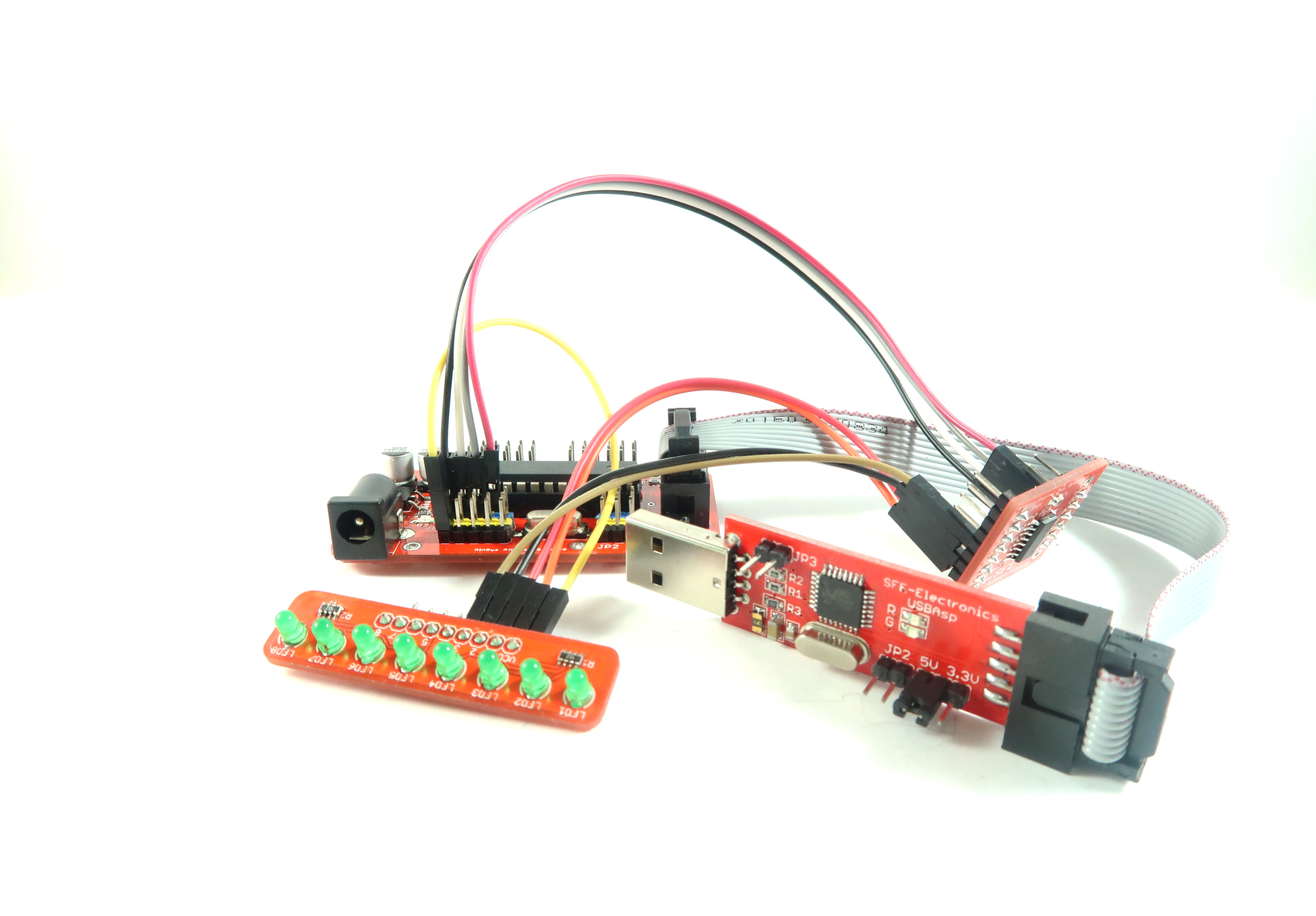
MUX / Demux breakout module is a module that can be used to add, either from the input or output of the micro-controller pin. This module really helps us if we experience deficiencies in the output pin or input pin. In this case example, the MUX / Demux breakout will be used to control the dimming level of the flame of 8 LEDs by using 1 output pin of PWM.
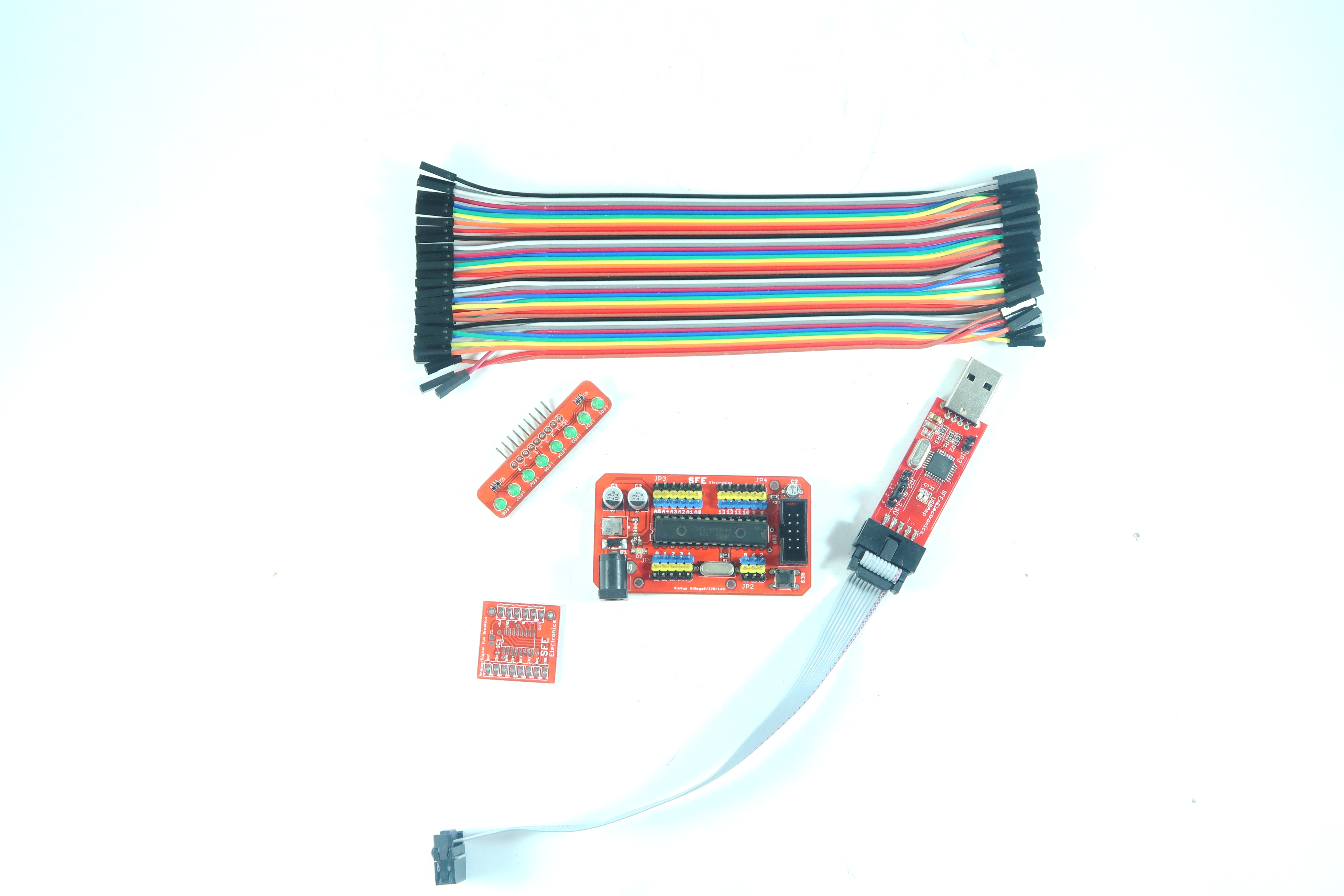
Materials You Need

Setup

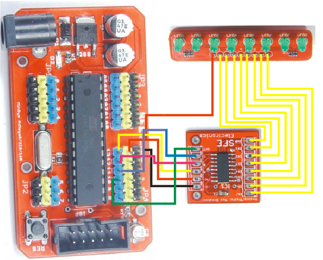
Connect SFE Minsys Atmega8/168/328, SFE Mux Breakout, and SFE 8 LEDs Module with jumper wires as schematic above.
Code

First, open Arduino IDE. The next step is to declare the pin that will be used i.e 3 pins for the selector and 1 pin for the PWM output.
#define selectorA 13
#define selectorB 12
#define selectorC 11
#define outPWM 10
Then, initialization of the pin used.
void setup() {
// initialize digital pin 13 as an output.
pinMode(selectorA, OUTPUT);
pinMode(selectorB, OUTPUT);
pinMode(selectorC, OUTPUT);
pinMode(outPWM, OUTPUT);
}
Then, create a function to make a selector which will be active.
void activSel(int a, int b, int c)
{
digitalWrite(selectorA, a);
digitalWrite(selectorB, b);
digitalWrite(selectorC, c);
}
In the Loop function, call the activSel function and then give the PWM output as follows.
void loop() {
activSel(0,0,0);
analogWrite(outPWM, ~255);
delay(1000);
activSel(0,0,0);
analogWrite(outPWM, ~100);
delay(1000);
}
In the activSel function call, 3 values are given, namely selector A = 0, selector B = 0, and selector C = 0 which means the output of the MUX / Demux breakout at output 1. While the output of the PWM is inversed because the LED module is active LOW. Here is the truth table of the 3 pieces of selector.
#define selectorA 13
#define selectorB 12
#define selectorC 11
#define outPWM 10
// the setup function runs once when you press reset or power the board
void setup() {
// initialize digital pin 13 as an output.
pinMode(selectorA, OUTPUT);
pinMode(selectorB, OUTPUT);
pinMode(selectorC, OUTPUT);
pinMode(outPWM, OUTPUT);
}
// the loop function runs over and over again forever
void loop() {
activSel(0,0,0);
analogWrite(outPWM, ~255);
delay(1000);
activSel(0,0,0);
analogWrite(outPWM, ~100);
delay(1000);
}
void activSel(int a, int b, int c)
{
digitalWrite(selectorA, a);
digitalWrite(selectorB, b);
digitalWrite(selectorC, c);
}