How to Connect and Calibrate the ADXL345 With Arduino
by mahmoodmustafashilleh in Circuits > Microcontrollers
4363 Views, 1 Favorites, 0 Comments
How to Connect and Calibrate the ADXL345 With Arduino
.png)

Welcome to this tutorial on the ADXL345 accelerometer sensor and how to interface it with an Arduino. The ADXL345 is a popular 3-axis accelerometer that measures acceleration in three directions: X, Y, and Z. This sensor is often used in various applications, such as robotics, gaming, and wearable technology.
In this tutorial, we will walk you through the provided Arduino code, which demonstrates how to set up and calibrate the ADXL345 sensor. Calibration is an essential step to ensure accurate measurements. We'll discuss the code's functions, explain the sensor's configuration, and guide you through the calibration process for accurate data collection.
By the end of this tutorial, you'll have a better understanding of how the ADXL345 sensor works and how to calibrate it to achieve reliable acceleration data. This knowledge will be valuable in your Arduino-based projects that involve motion and orientation sensing.
Let's get started by examining the code and understanding how it communicates with the ADXL345 sensor, configures it, and calibrates it for accurate measurements.
-----
Before we delve into the topic, we invite you to support our ongoing efforts and explore our various platforms dedicated to enhancing your IoT projects:
- Subscribe to our YouTube Channel: Stay updated with our latest tutorials and project insights by subscribing to our channel at YouTube - Shilleh.
- Support Us: Your support is invaluable. Consider buying me a coffee at Buy Me A Coffee to help us continue creating quality content.
- Hire Expert IoT Services: For personalized assistance with your IoT projects, hire me on UpWork.
Explore our Stores for Premium Products:
- ShillehTek Store: Access exclusive discounts on Arduino, Raspberry Pi sensors, and pre-soldered components at our ShillehTek Website.
Shop on Amazon:
Supplies
https://shillehtek.com/collections/all - ShillehTek ADXL345
Physical Connection
You should set up an I2C connection with the device as follows:
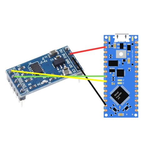
We need four jumper wires. In this case, I am using a two-sided ADXL and an Arduino Nano, but in reality, you can use any ADXL model or Arduino controller as long as you match the connections!
Code
Run the following code on the device
#include <Wire.h>

int ADXL345 = 0x53; // The ADXL345 sensor I2C address
float X_out, Y_out, Z_out; // Outputs
int X_offset = 0, Y_offset = 0, Z_offset = 0; // Offset values

void setup() {
  Serial.begin(9600);
  Wire.begin();
  configureADXL345(); // Configure the sensor
  // Note: You should calibrate upon re-powering the sensor
  // Uncomment if you want to calibrate
  // calibrateADXL345(); // Calibrate the sensor
}

void calibrateADXL345() {
  // You should calibrate with the positive axis pointed upwards against gravity
  // You should calibrate each axis separately and change the offset constant,
  // You need to run this code three times if you want to calibrate all three axes
  float numReadings = 500;
  // float xSum = 0;
  // float ySum = 0;
  float zSum = 0;
  Serial.print("Beginning Calibration");
  Serial.println();
  for (int i = 0; i < numReadings; i++) {
    Serial.print(i);
    Serial.println();
    Wire.beginTransmission(ADXL345);
    Wire.write(0x32); // Start with register 0x32 (ACCEL_XOUT_H)
    Wire.endTransmission(false);
    Wire.requestFrom(ADXL345, 6, true);
    X_out = (Wire.read() | Wire.read() << 8);
    Y_out = (Wire.read() | Wire.read() << 8);
    Z_out = (Wire.read() | Wire.read() << 8);
    // xSum += X_out;
    // ySum += Y_out;
    zSum += Z_out;
  }
  //// 256 is the raw value for 1g, (we calibrate at 1g hence why we take the difference)

  // X_offset = (256 - xSum / numReadings) / 4;
  // Serial.print("X_offset= " );
  // Serial.print(X_offset);
  // Y_offset = (256 - ySum / numReadings) / 4;
  // Serial.print("Y_offset= " );
  // Serial.print(Y_offset);

  Z_offset = (256 - (zSum / numReadings)) / 4;
  Serial.print("Z_offset= " );
  Serial.print(Z_offset);
  Serial.println();
  delay(1000);
  // We need to add it to the offset channel respectively =
  // Once you write to the offset channel you do not need to do it again,
  // unless you unpower and power the device
  // Each offset address is different for X, Y, and Z

  // Wire.beginTransmission(ADXL345);
  // Wire.write(0x1E);
  // Wire.write(X_offset);
  // Wire.endTransmission();
  // Wire.beginTransmission(ADXL345);
  // Wire.write(0x1F);
  // Wire.write(Y_offset);
  // Wire.endTransmission();
  Wire.beginTransmission(ADXL345);
  Wire.write(0x20);
  Wire.write(Z_offset);
  Wire.endTransmission();
}

void configureADXL345() {
  Wire.beginTransmission(ADXL345);
  Wire.write(0x2D); // Access/ talk to POWER_CTL Register - 0x2D
  Wire.write(8); // Enable measurement (D3 bit high)
  Wire.endTransmission();
  delay(10);
}

void loop() {
  Wire.beginTransmission(ADXL345);
  Wire.write(0x32); // Start with register 0x32 (ACCEL_XOUT_H)
  Wire.endTransmission(false);
  Wire.requestFrom(ADXL345, 6, true);
  X_out = (Wire.read() | Wire.read() << 8);
  X_out = X_out / 256;
  Y_out = (Wire.read() | Wire.read() << 8);
  Y_out = Y_out / 256;
  Z_out = (Wire.read() | Wire.read() << 8);
  Serial.print(Z_out);
  Z_out = Z_out / 256;

  Serial.print("Xa= ");
  Serial.print(X_out);
  Serial.print("   Ya= ");
  Serial.print(Y_out);
  Serial.print("   Za= ");
  Serial.println(Z_out);
  delay(500);
}
The code provided includes the following sections:
Setup: In the setup() function, the code initializes serial communication for debugging, sets up I2C communication, configures the ADXL345 sensor, and calls the calibration function. You should only call the calibration function initially when re-powering, then uncomment it in practice. The sensor is able to remember the calibration value as long as it remains on. See video above for further details on how to use this code for calibration.
Calibration: The calibrateADXL345() function is responsible for calibrating the sensor. Calibration should be performed with the positive axis (e.g., X, Y, Z) pointed upwards against gravity; you need to do one at a time in this code (room for improvement on the code level for sure). For example, when calibrating the Z-axis, the code collects data from the Z-axis (vertical) acceleration and calculates an offset value (Z_offset) based on the difference between the raw sensor values and a known value (256 for 1g). This offset is later applied to correct measurements and is written back to the sensor's register. You will need to uncomment and comment accordingly to calibrate the X and the Y. When the sensor is calibrated it should be as steady as possible, ideally using a calibration block.
Configuration: The configureADXL345() function sets up the ADXL345 sensor by accessing the POWER_CTL register to enable measurements.
Loop: In the loop() function, the code continuously reads acceleration data from the ADXL345 sensor. It sends an I2C request to get the raw acceleration values for the X, Y, and Z axes, converts these values to meaningful data, and prints them to the Serial Monitor. This code allows you to interface with the ADXL345 accelerometer, configure it, and calibrate it for accurate measurements of acceleration in multiple directions. You can further utilize this data in your Arduino projects, such as detecting motion or controlling devices based on orientation.
Conclusion
Hope this high-level overview of the code makes sense, you do not need to calibrate if you do not want to; it is only meant for improvement of results! Hope you got it working and enjoyed the tutorial. Do not forget to subscribe to our Youtube channel above for more in depth guides on projects. Stay tuned!