How to CNC Router Human Feet (or How to Use Fusion CAM)
by imadeathing in Workshop > CNC
5235 Views, 32 Favorites, 0 Comments
How to CNC Router Human Feet (or How to Use Fusion CAM)
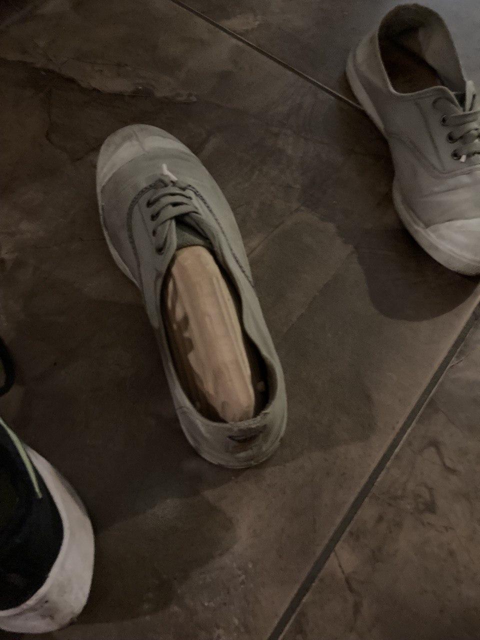
Hi! I'm Sam, an 11th grader at the Nueva School. I used Fusion 360 and the CNC router to make a pair of feet from a CT scan of a real foot which I plan on putting on the legs of a "footstool" to maximize the "pun"tential and store my shoes on. Another use I've been toying with is to make them "shoe hooks" by mounting them onto the wall to free up floor space.
I don't have much experience with, or formal education in Fusion 360, so I learned a lot during this project through trial and error, googling, and bothering shop managers. The main new skill/tool I learned was how to CAM in Fusion. Having only ever done 2D CAM in Vcarve before, I had a lot to learn. Through this project, I learned about various tool paths, adjusting feeds/speeds to minimize machining time, setting fixtures, Gwizard, and more in addition to features in Fusion CAD.
Supplies
Tools
- CNC router (specify model)
- 1/4" ball nose end mill
- 1/2" flat end mill
- 1/4" drill bit
- sandpaper
- vise
- hot glue gun
- saw
- file
Software
- Fusion 360
- Gwizard (optional)
Materials
- 4 big blocks of cedar (2 per foot)
- The exact size will depend on your foot size, model offset, hold down strategy, and more
- 1/4" dowels
- wood glue
- sacrificial plywood (bigger than cedar)
Finding / Importing File
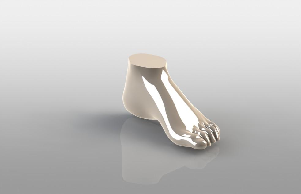
I found a CT scan of a human foot off of GrabCAD, downloaded it, then imported it into Fusion 360. Any foot model should work. I did the first version with a mannequin foot before realizing that it didn't have human proportions and therefore didn't fit in my shoe. I also tried using apps that generate a model of your foot through strategically taken overlapping photos but none of them would give me a 3D file to use.
This is the file I used: https://grabcad.com/library/human-foot-1
Scaling
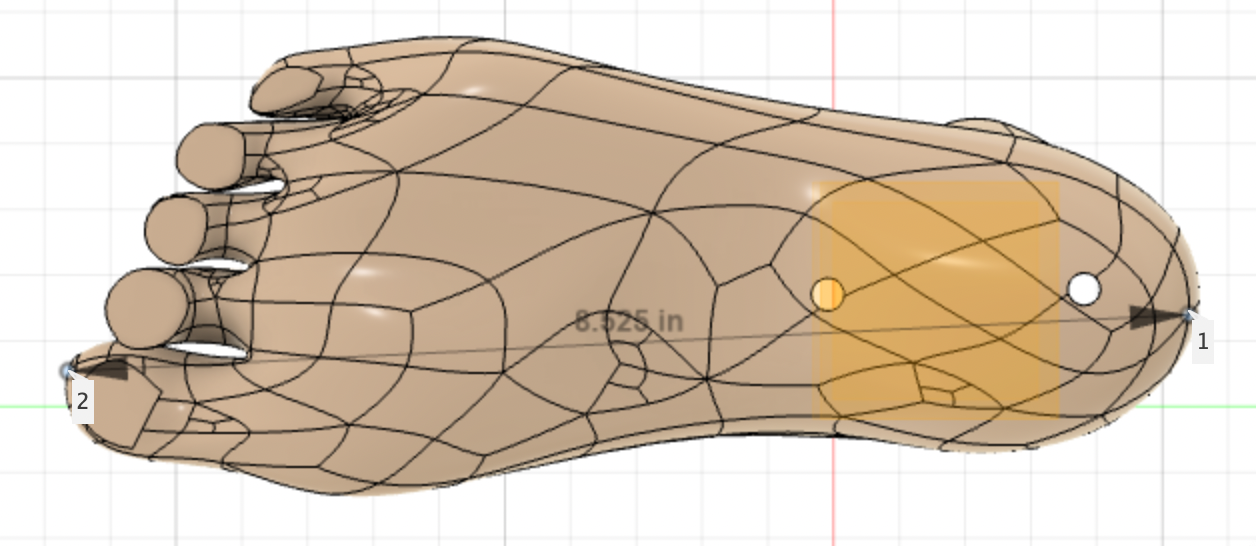
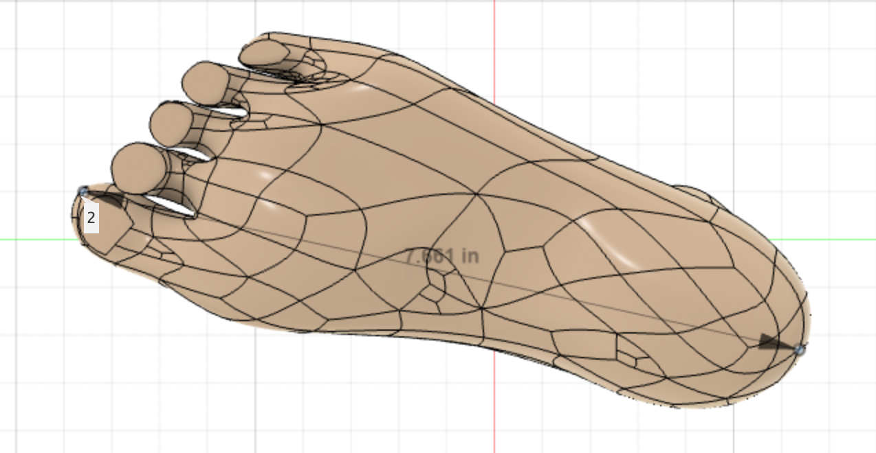
The first thing to do is measure the length of your own foot which you will scale the model down/up to. I found my foot to be 8.5". The original model was 7.661" so with simple algebra, I found the scale factor to be 1.109. Also, make sure that the cross-sectional flat part is parallel with the x-axis which will allow you to place that at the edge of your stock later.
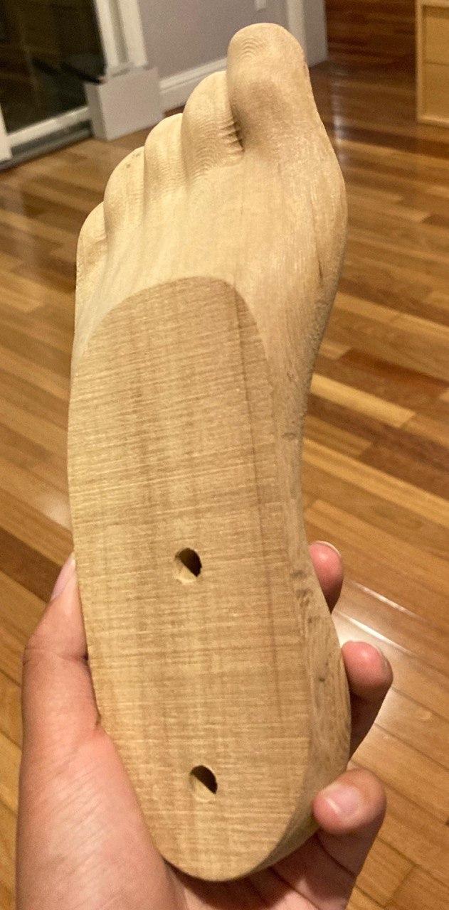
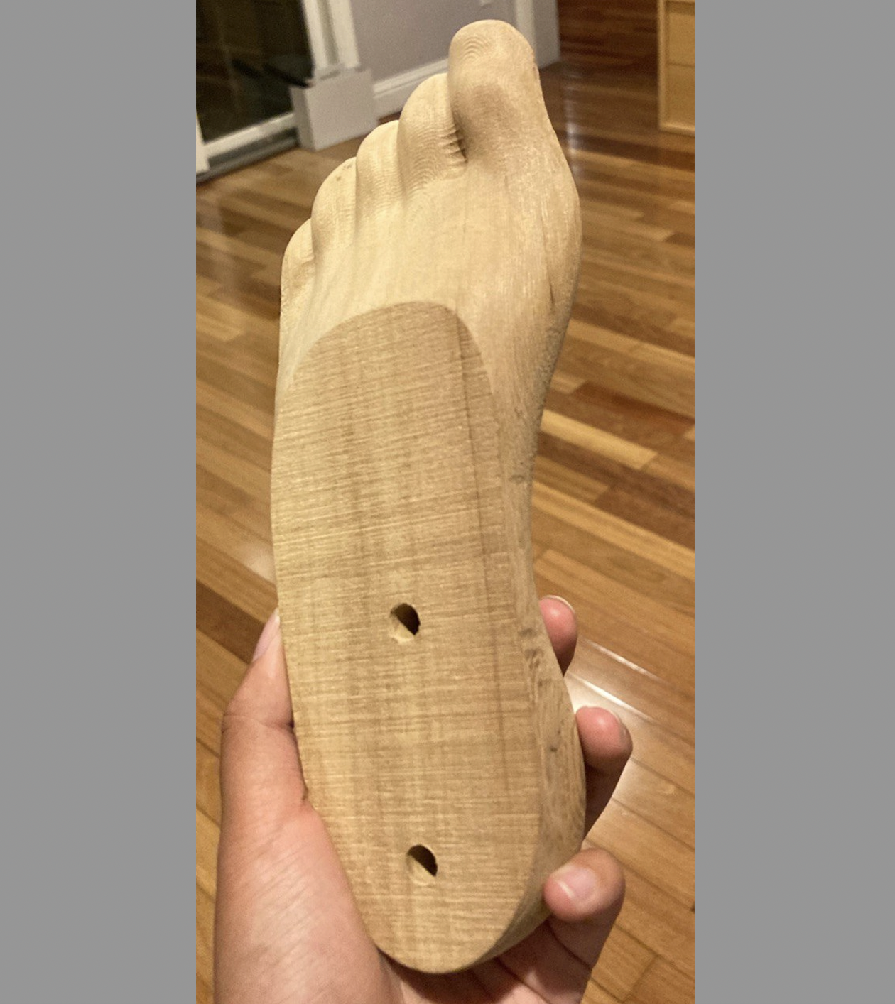
Holes
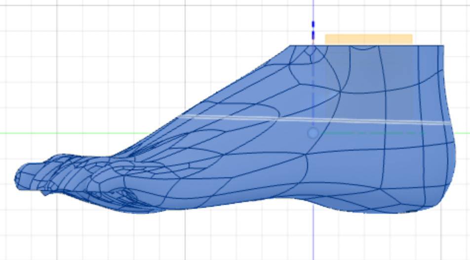
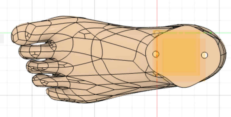
The model is taller than the bit length which means you need to split the model into two parts. Offset a plane to half the height of the model and then use it to split the model into two bodies; a bottom and a top. Before separating the two bodies, make two 1/4" holes that go through both halves, which will be used later to align the two parts correctly when gluing them together. Then make two copies of the file and delete the bottom body from one, and the top body from the other.
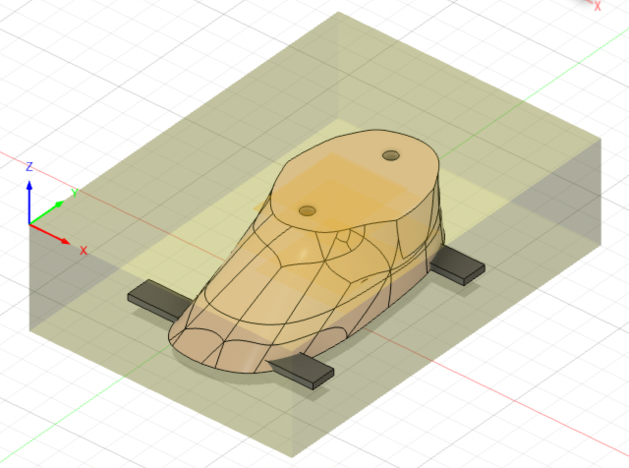
Tabs
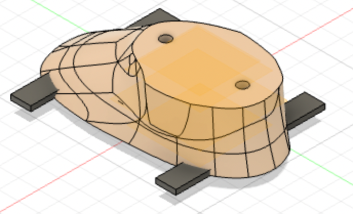
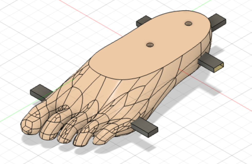
You will need to manually add tabs to the model so that it stays in place while machining. Make a new sketch then create five 0.5" x 0.125" rectangles placed at the 5 most convex heights evenly spaced around the sides. Then extrude each 1".
Do this for both halves of the foot
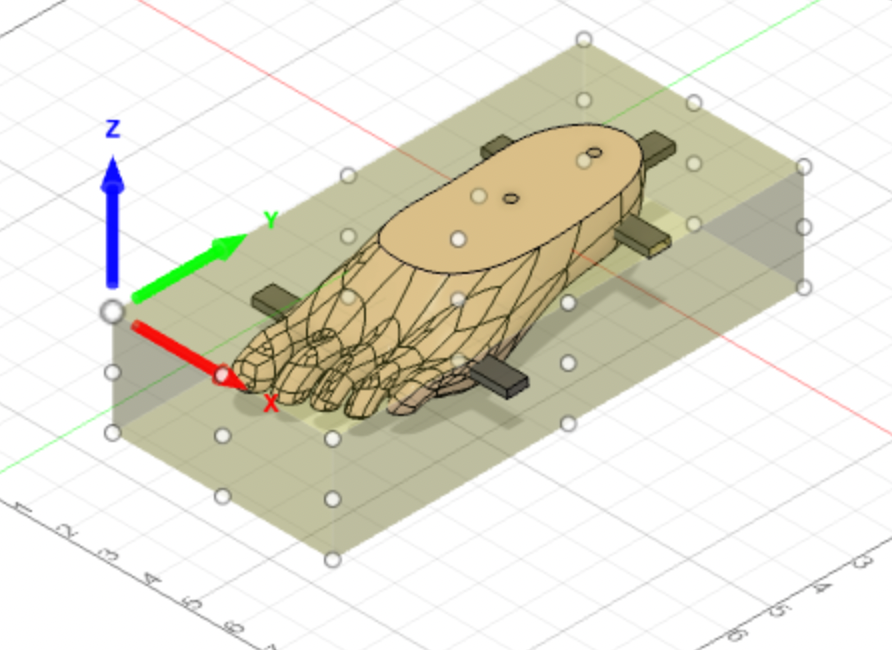
Setup
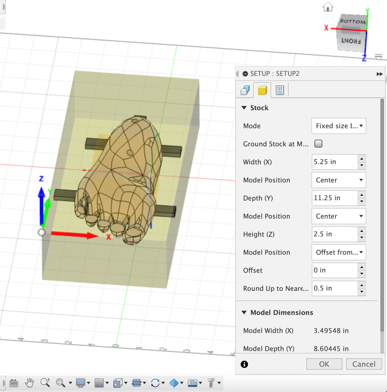
In the top left, switch the workspace from Design to Manufacturing. I suggest starting with the toes body because it is more complicated. Because it is a rather complex shape, with both convex and concave sections, especially around the toes, you first machine one side, then flip it over to machine the other. The challenge will be in making sure to place the stock in the same place and the right orientation while flipping. I also suggest starting with the underside of the foot because it allows for the surface that will eventually be glued to the other body to be at the bottom of the stock, and therefore stay flat without having to change to a flat end mill and facing it.
Create a new setup by going to "setup" in the top left, and clicking "new setup". Under "Work Coordinate System" choose to put the origin at a stock box point and made sure that with the body upside down, the origin is at the front top left corner.
Select the body of the foot to be the model and the tabs you just made to be the fixtures.
Moving over to the stock tab, choose the "relative size box" tab and made the stock side offset 0.75" and the stock top offset 0.25". These are rough estimates for now that can be readjusted after finding the wood and cutting it down to size.
Projecting
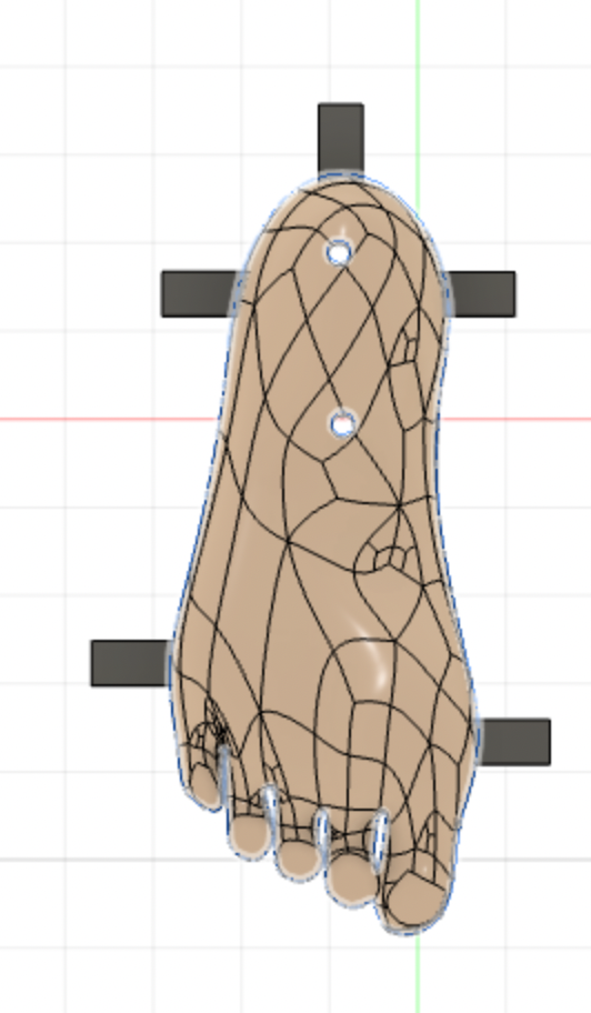
In anticipation of the tool paths you will be creating in the next few steps, you need to go back to the Design workspace and project the outline. Create a new sketch and press P to bring up the projection tool. Select the foot body and make sure you are projecting a body. Once you have a projection, you need to convert it to construction/sketch lines to be usable later. Select all the projection lines and right-click "break link".
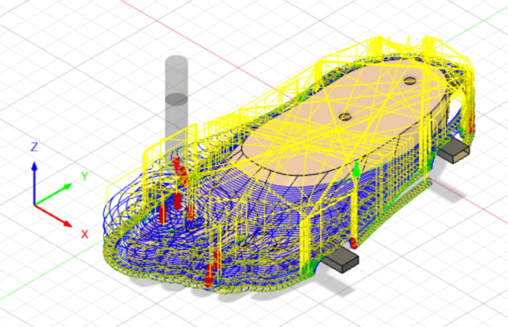
Adaptive Clearing
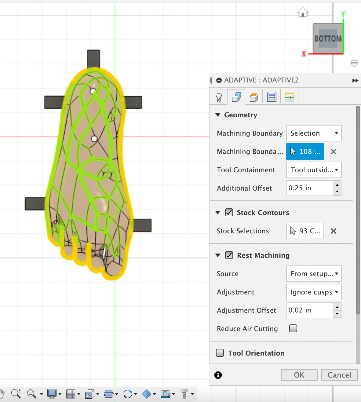
Go back to the manufacturing workspace. Start with an adaptive clearing toolpath to quickly machine away a lot of material. Select the tool you will be using. I used a 1/2" flat end mill that allowed me to be more aggressive in the rate of material being removed. For now, leave the rest of the settings in "tool" tab unchanged. You can mess around with them later after looking at numbers in Gwizard. In the "Geometry" tab, change the machining boundary to selection. Then select all the projection lines you just converted to sketch lines for the "machining boundary selection" field. Add an additional offset at least the diameter of your tool.
There are many very specific settings in each of these tool paths. I won't go through all of them but I will highlight any important changes I made. Much of what you choose to do will depend on your specific model, and any restraints you might have with your machine/bit/other.
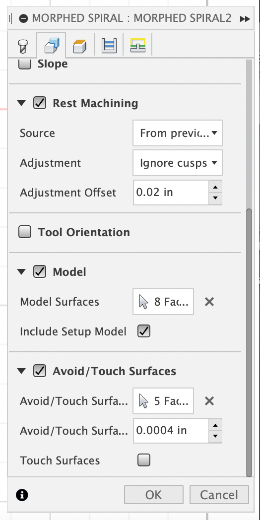
In every tool path, I have checked the "rest machining" checkbox.
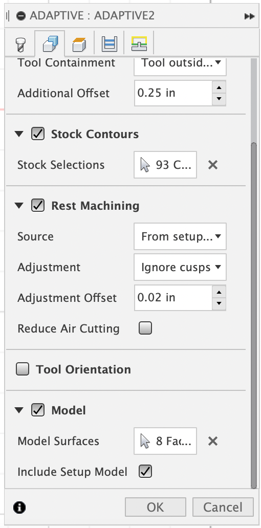
At the very bottom of the "Geometry" tab, you will find the "model" field. Make sure you select both the body as well as your tabs as "model surfaces". Also, remember to click "include setup model" at the bottom. This will make sure the model it machines will be what you specified in your setup. If you don't click this, what you selected in "model surfaces" will override it. This isn't really a problem if you don't have fixtures but if you do have fixtures, this will cause it to either treat the fixtures as something to machine around, defeating their purpose, or machine straight through them.
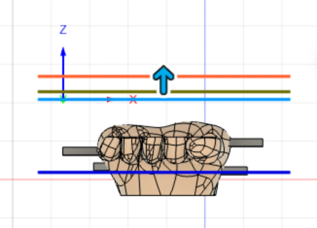
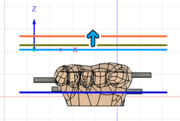
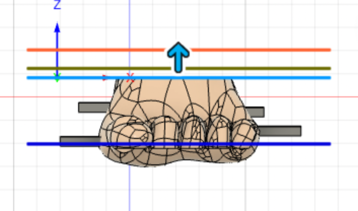
Switch over to the "Heights" Tab. Make sure that the bottom height is right below the lowest tab, so that it clears every tab. The rest of the heights should be fine left at the default.
Switch to the "Passes" tab. We can also mess around with these numbers a bit after we use the Gwizard calculator to find the optimal feeds/speeds.
Because this is a roughing pass, make sure to click "stock to leave" and set both radial and axial at 0.125" which will be cleaned up with a more precise tool path later.
Click OK. It will start generating the toolpath.
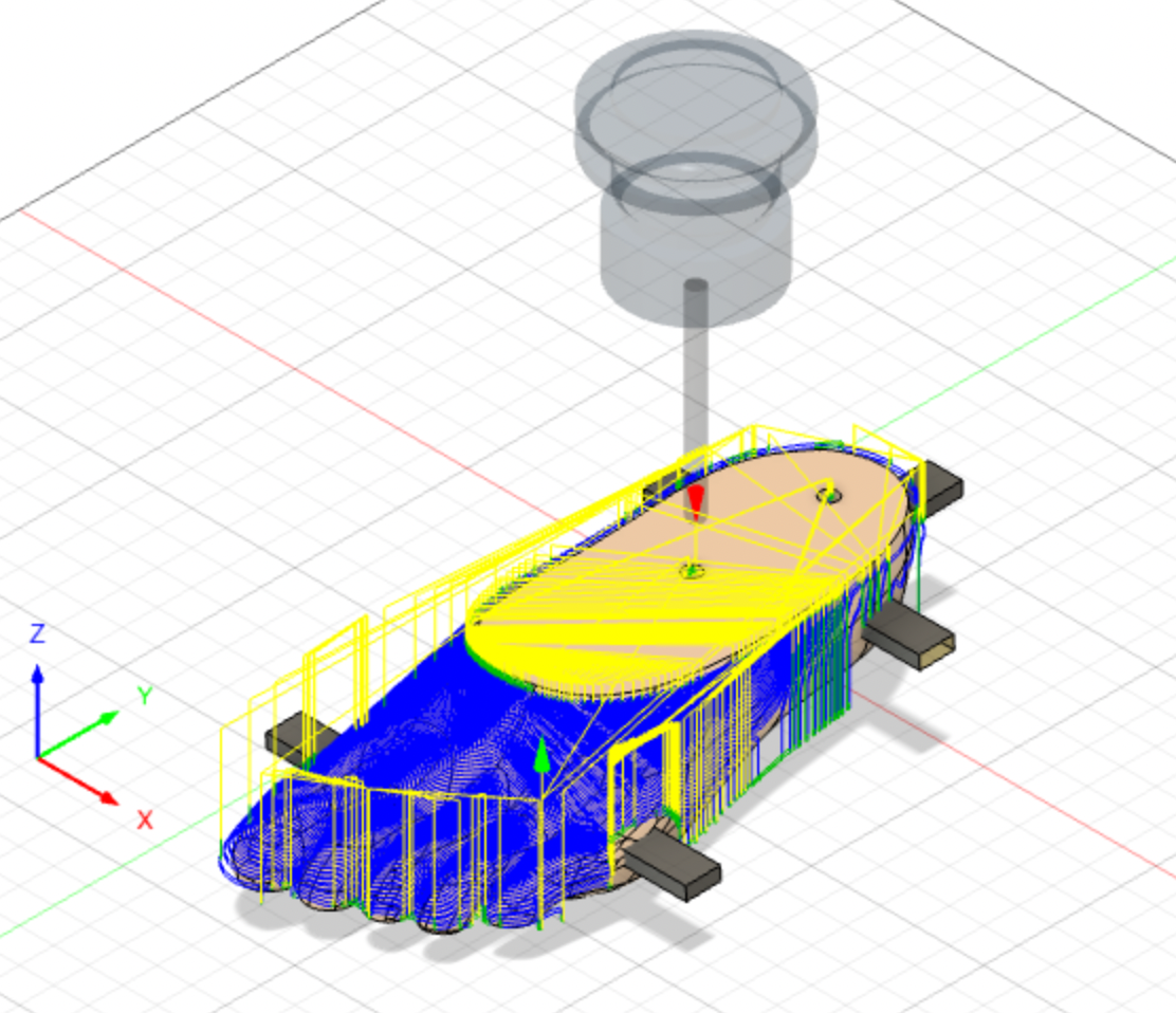
Morphed Spiral

Now use a morphed spiral toolpath to clean up the edges and produce a nicer finish. I switched to a 1/4" ballnose bit for more precise machining around the toes.
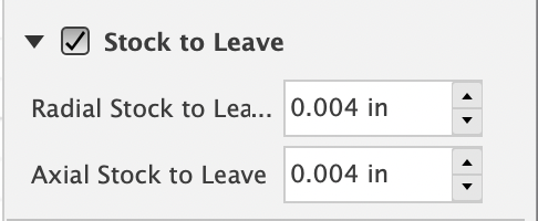
Once again, leave the settings in "tool" tab unchanged for now. The "Geometry", "Height" and "Passes" tabs should be the same as in the adaptive clearing toolpath with a few exceptions. In "Geometry", a morphed spiral also has an option for things not to touch. Just as an extra precaution, add the tabs to that field. Also, change the "stock to leave" to .004" because we want this to be as similar to the model as possible.
Click OK.
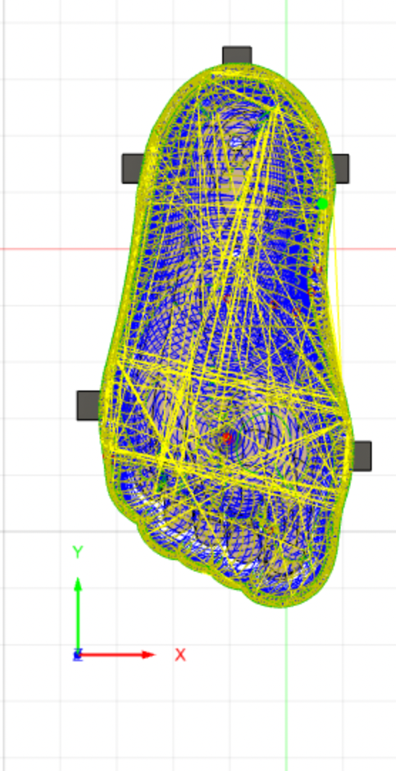
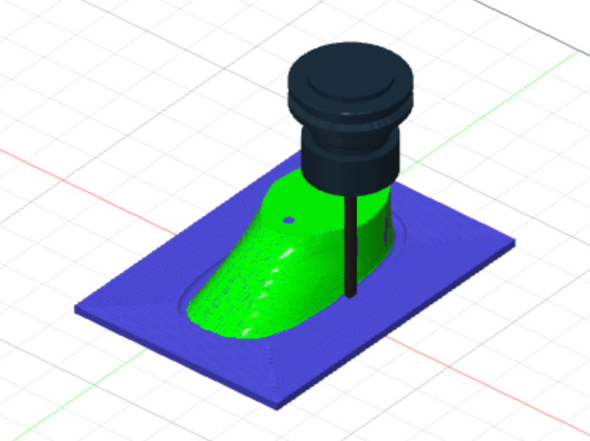
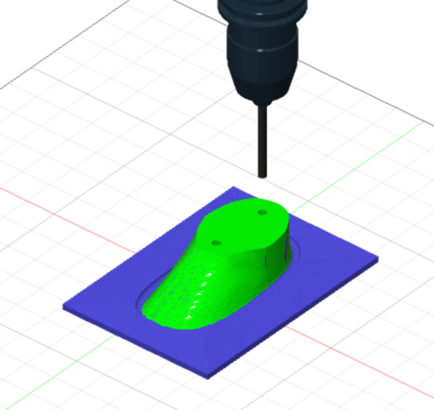
Simulate
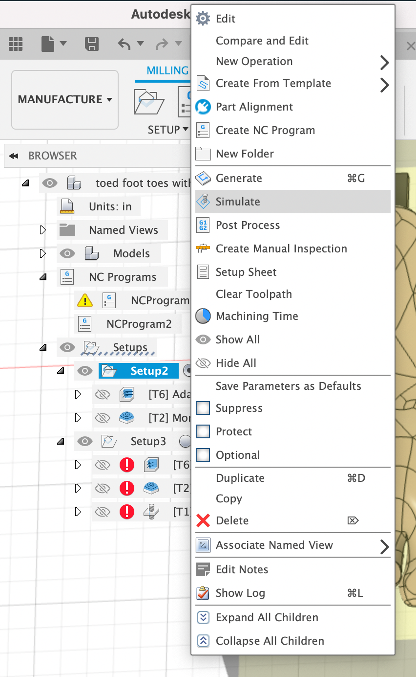
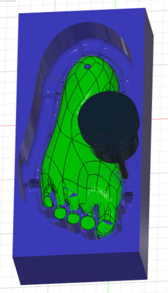
This is a good spot in the process to simulate the toolpaths which will allow you to check for any collisions and make sure the toolpaths are doing what you expected. Right-click on the setup to simulate. I like to turn off the toolpath visualization to better see the resulting model.
Flip + New Setup
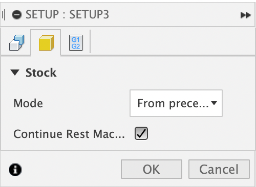
Now that we are done with one side, we will do the same thing on the other side.
Flip the model view and move the origin to the same spot in space as your previous setup. In the "stock" tab, click "from preceding setup". This will help it remember where your model is in your stock, and allow you to not have to mess with your zeroes in-between tool paths.
Adaptive Clearing
Repeat step 7, but now on the top side of the foot. Make sure that the bottom height is still below the bottom tab, which is what was previously in step 7 the top tab.
Morphed Spiral
Again, repeat step 8 but on the top side. The heights should be the same as step 11. Remember that this model is positioned at the bottom of the stock so there should be any machining on the top.
Drill Holes
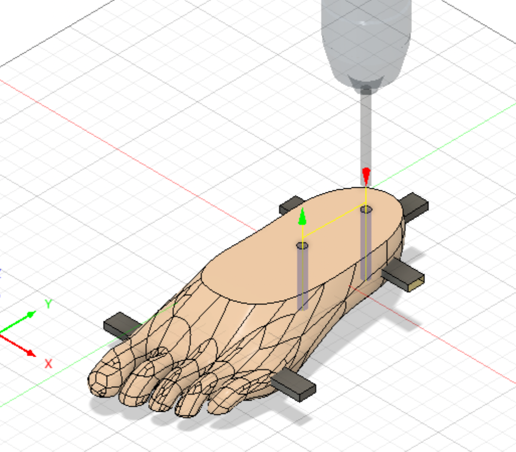
The final toolpath is to drill 1/4" holes so that you can line up the two halves exactly with two dowels when glueing together. Use the "drill hole" toolpath and select the holes you made in step 3. Make sure that the hole goes all the way through the model.
Gwizard
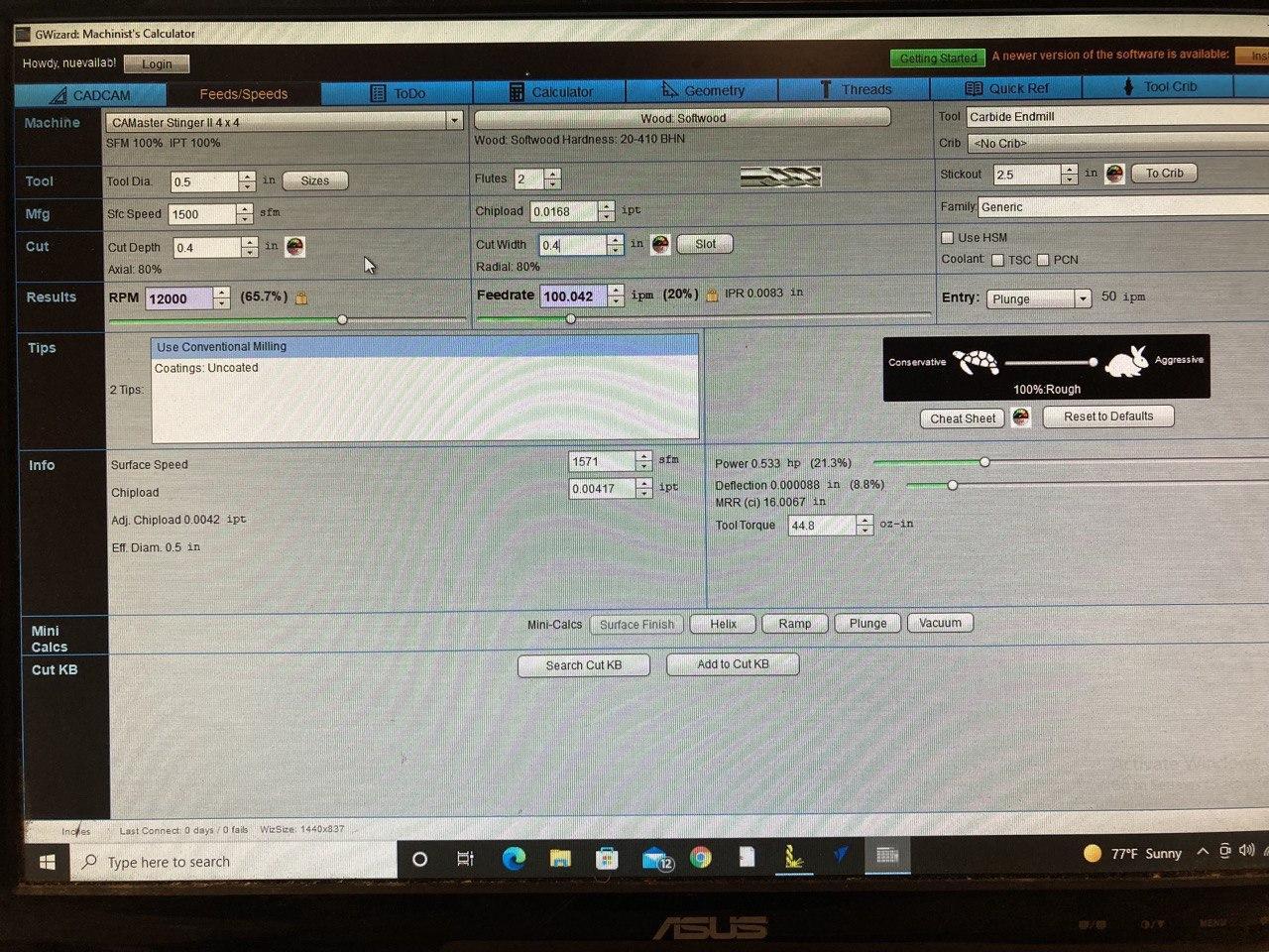
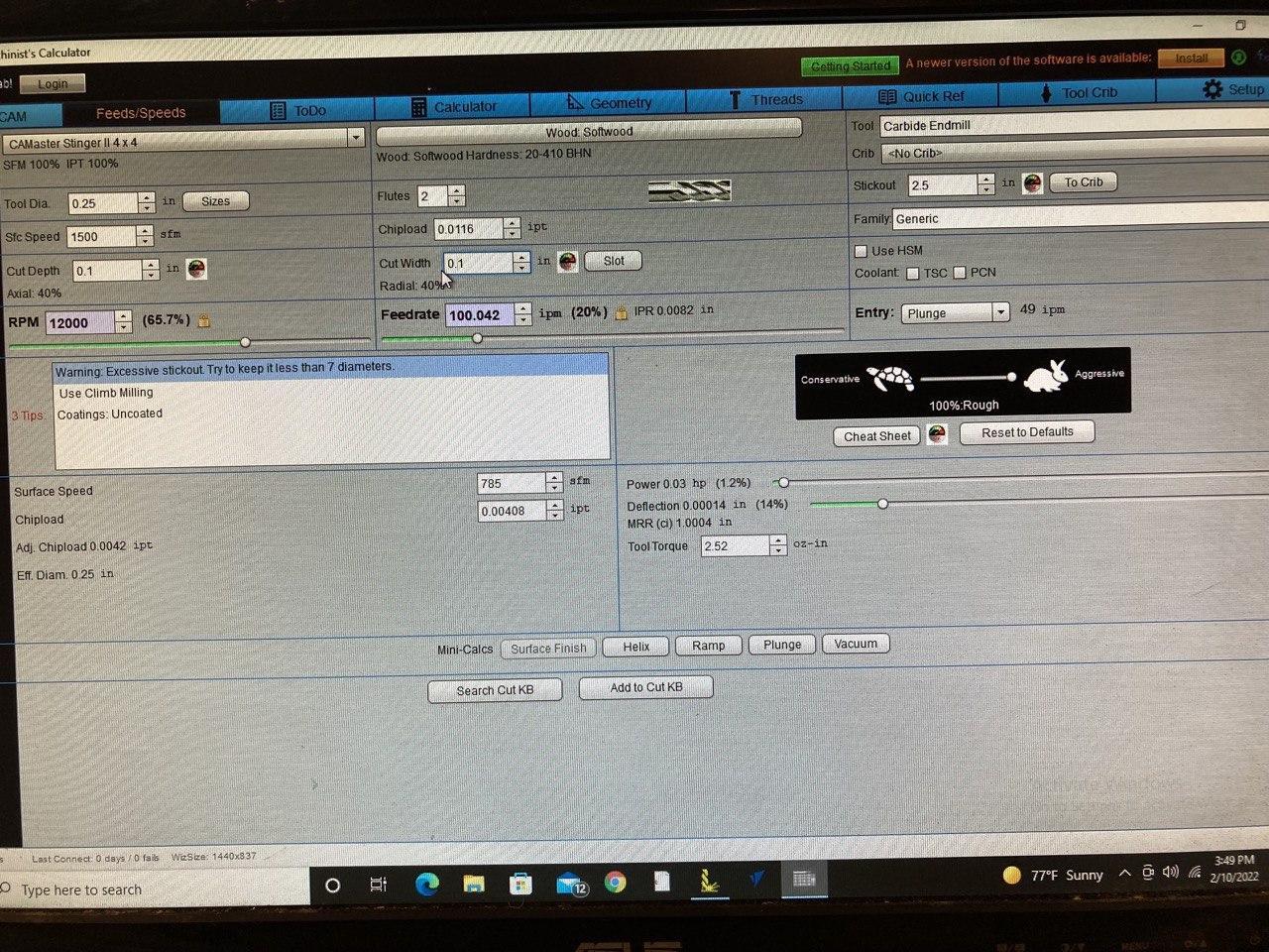
Now that you have all the toolpaths, you can go into Gwizard and play around with different cut depths, cut widths, spindle speed, and feedrate until you are satisfied the both the power and deflection percentages. This step is optional and you can also look up a chart for suggested settings. Once you are satisfied, plug the numbers back into your toolpaths in the "tool" and "passes" tabs.
Repeat Steps 4-9 on Top Half of Foot
Repeat steps 4-8 on the top half of the foot. Instead of the morphed spiral in step 9, I chose to do a 3D contour as it seemed more appropriate for the shape.
Repeat Steps 13 on Top Half of Foot
Repeat step 13 on the top half of the foot.
Post Process
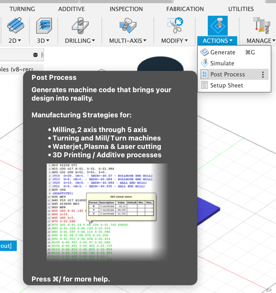
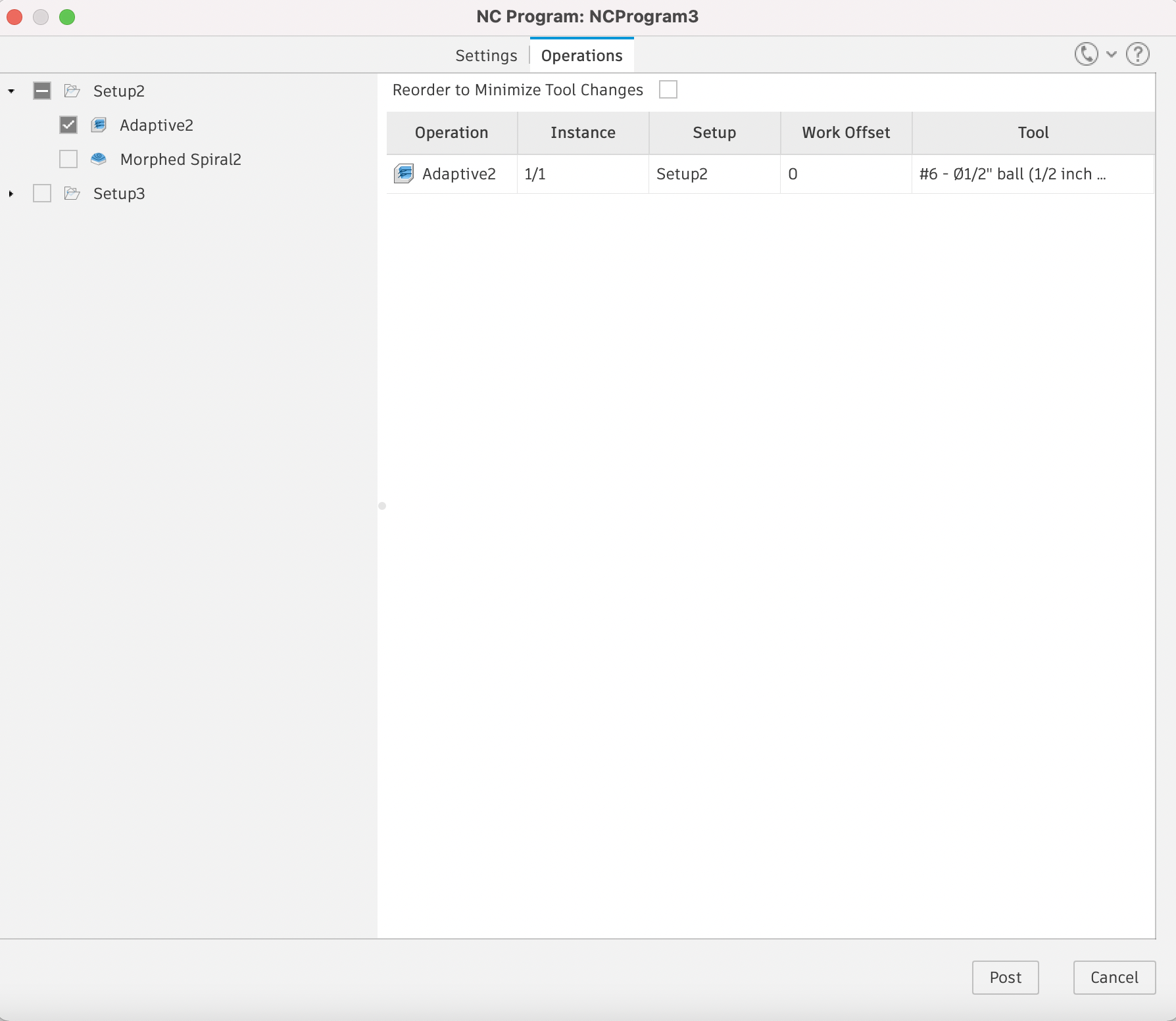
In the top bar under "actions", you will find "post process". Select the post and adjust the settings as appropriate for your machine. Make sure to do a separate one for each tool in each setup. Do this for both halves of the foot
Find Material and Adjust Stock Dimensions
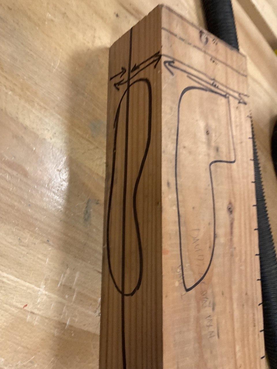
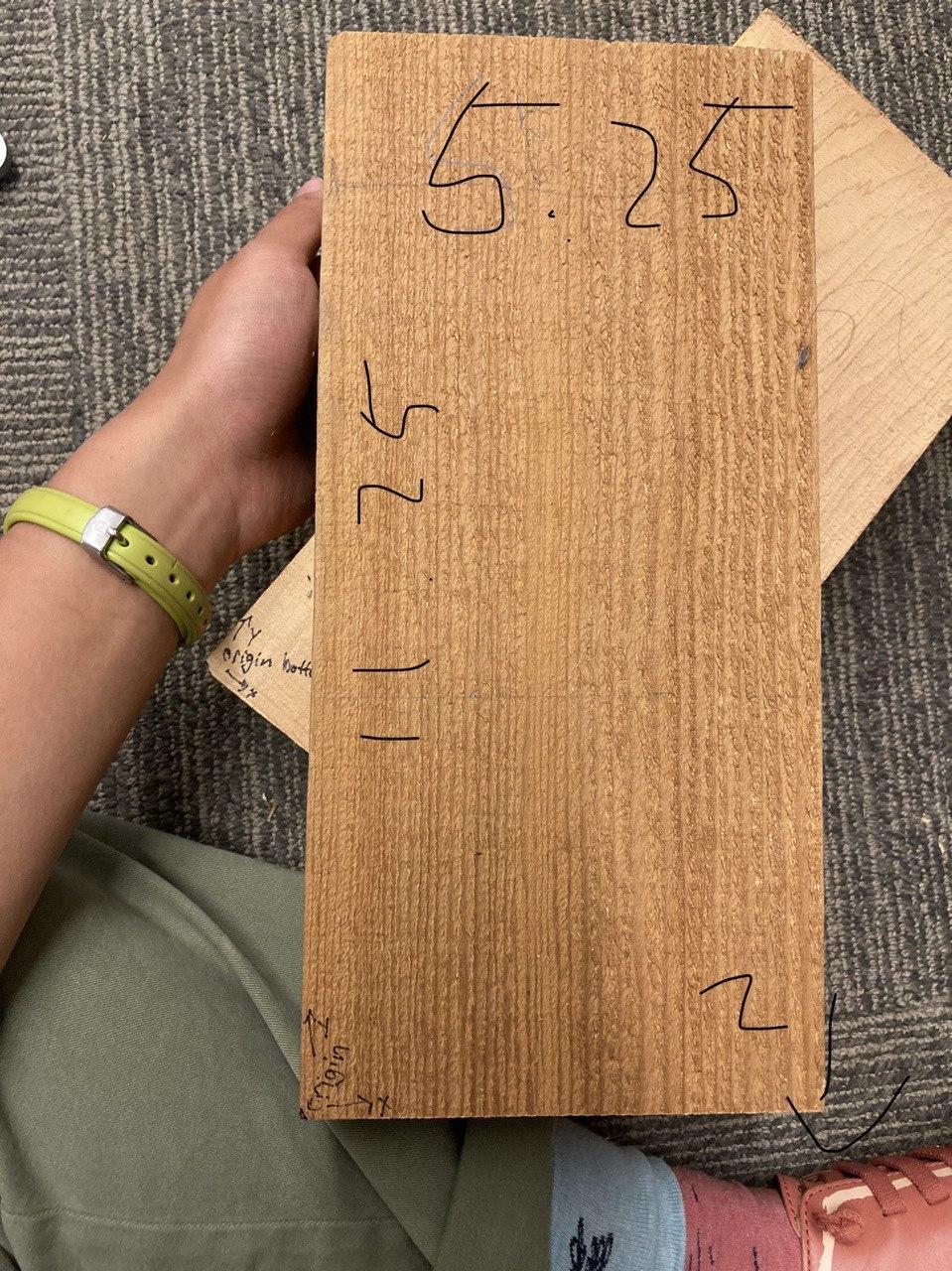
Now find suitable stock material (I used cedar) and cut it down to approximate size. Measure the piece and go back into your setups and make them match. You will need to switch from "relative size box" to "fixed-size box". Make sure that you have the origin still in the same corner, and that you do this for both setups. Give yourself enough extra stock on all the sides to accommodate for your "model offset" and any clamping to hold it down.
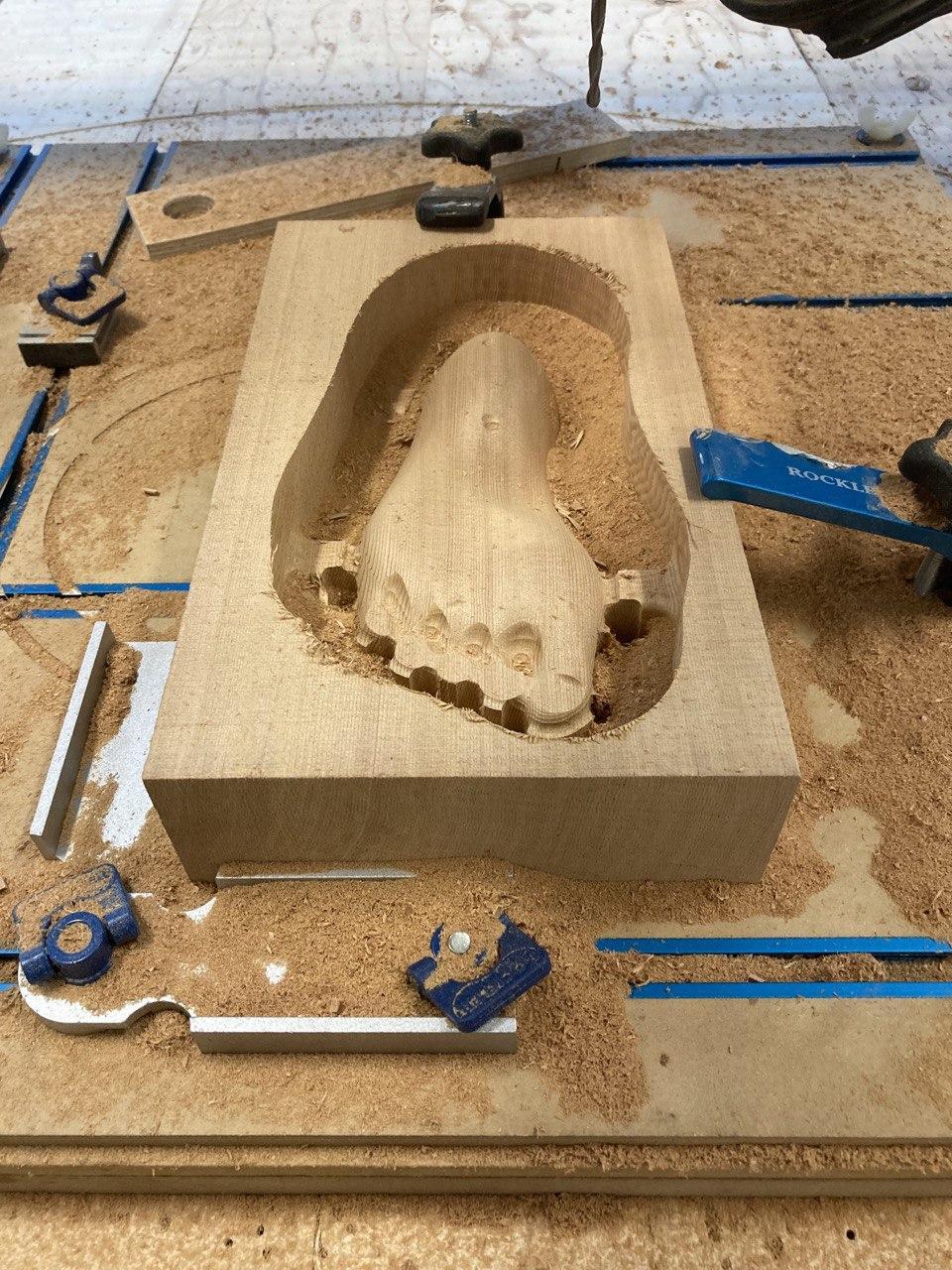
Put Material in Vise + Zero Axis
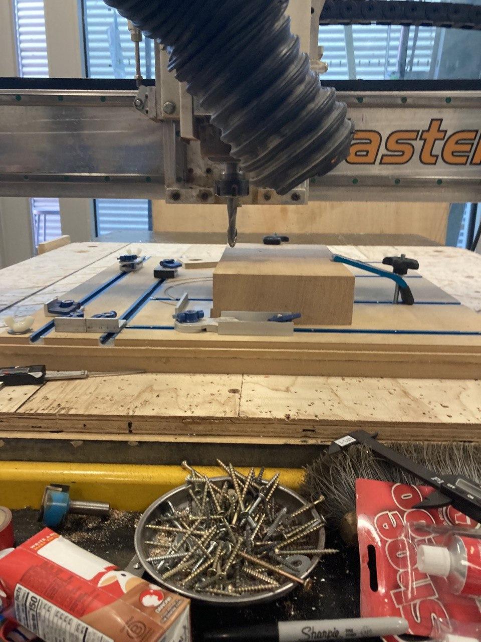
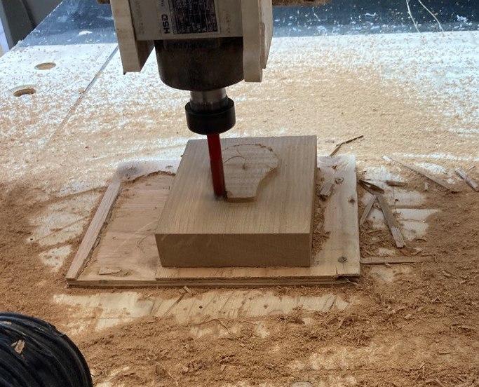
Find a good way to hold down your wood that won't result in vibrations, or collisions. For the toed half of the foot, I chose to use a t-track table top but a vise would also work. Because we aren't flipping the top half of the foot, I hot glued it down to a piece of plywood which I then screwed down. Find your origin and set your X and Y zeroes. Touch top on top of the stock for your Y zero.
Run Files

Run your files! Make sure to watch for any unexpected noises or movements.
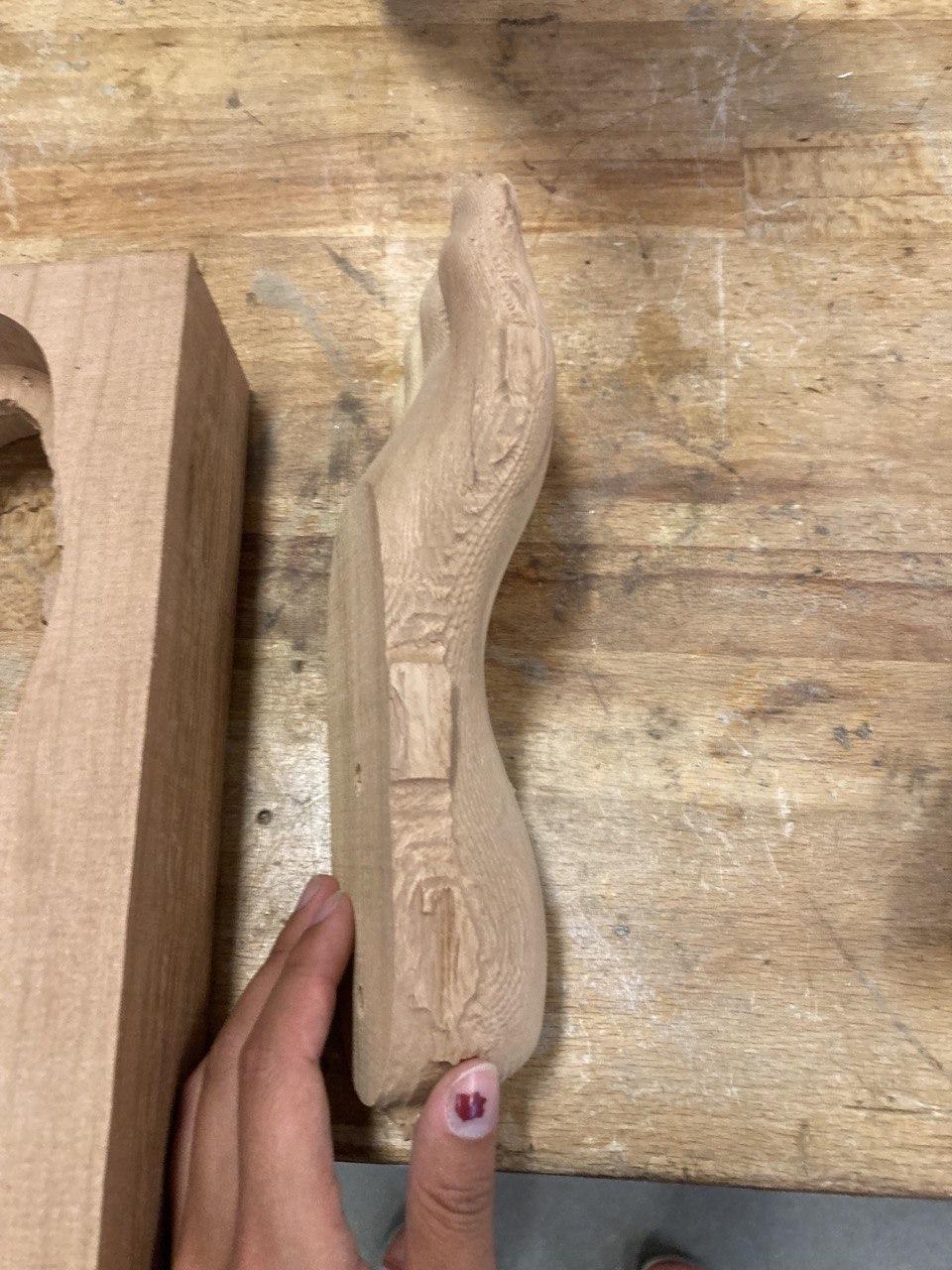
I personally ran into trouble at this step by screwing up my zeroes. This halted my progress because I couldn't find the same zeroes when I flipped the stock. I didn't have time to redo the machining before the submission date of this challenge (we are required to be watching the router the whole time it runs so finding 6 straight hours to sit in my school shop is rather difficult) but I got this far already. I don't have pictures for the rest of this instructable as I haven't done it yet but I know the methods work because I have used them in prior attempts at routering a foot.
Remove Tabs
Use a saw or chisel to remove the tabs
Glue Up With Dowels
Glue the two halves together using 1/4" dowels through the holes for alignment
Sand
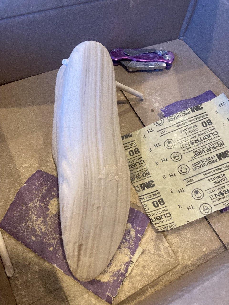

Sand down any areas until you are satisfied
And you are done! You can now use your feet in any project or try it in different materials. I personally am planning a "foot"stool where I can also store my shoes on, as well as shoe hooks to save floor space.
Enjoy people giving you weird looks for carrying feet around!
This was my first attempt at Fusion CAM and I will definitely be using it again to bring various ideas to life.