How to Build an IoT Based Smart Aquaponics Educational Garden
by kijanigrows in Circuits > Linux
3176 Views, 33 Favorites, 0 Comments
How to Build an IoT Based Smart Aquaponics Educational Garden
Introduction
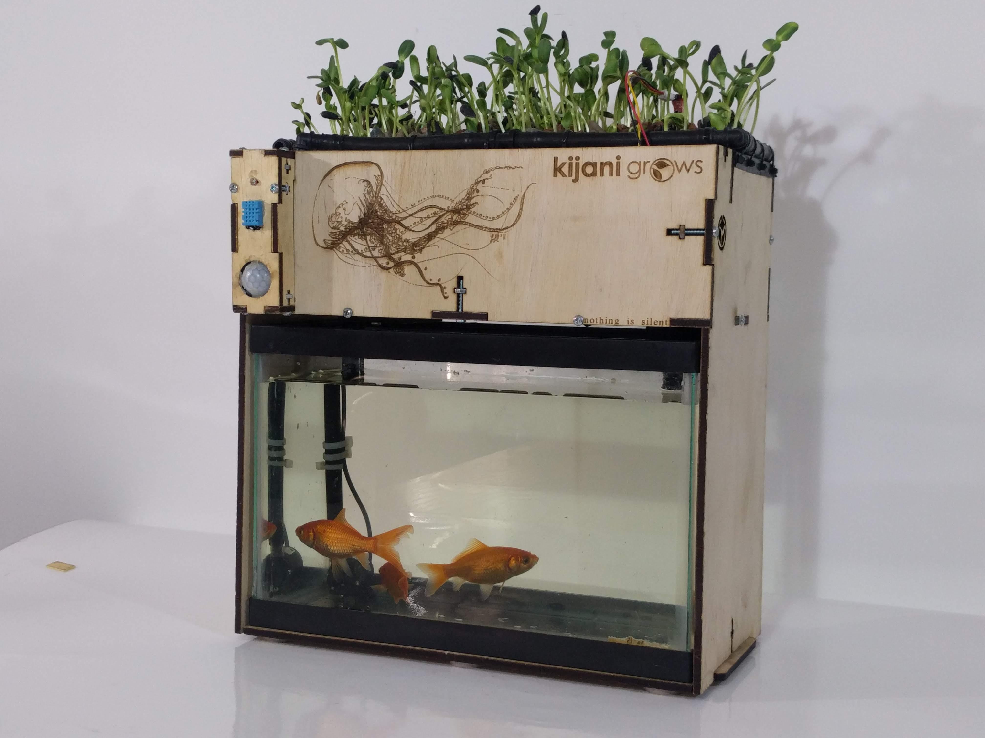
Aquaponics combines the basic principles of conservation of energy, the water cycle, the nitrogen cycle, aquaculture, and soilless farming to grow food. Smart Aquaponics integrates microcomputer technologies, allowing users to interact with these essential concepts from a data point of view. This kit has something in it for students of all ages. Its purpose is to explore fundamental concepts as compared to introducing a new curriculum.
This kit reduces friction in learning STEM, by combining life sciences, fabrication technologies, electronics engineering, software development, and fine art for an experiential learning journey that begins with understanding single-cell microbes to mimic these in an autonomous robotic system.
Educational Benefits:
- Integrated and exponential learning
- Teaches systems thinking from ecosystems to engineering
- Get kids interested in STEM, big Kids can ML,
- Builds strong foundations in engineering
- Improves critical reading and thinking
Assembling the Garden
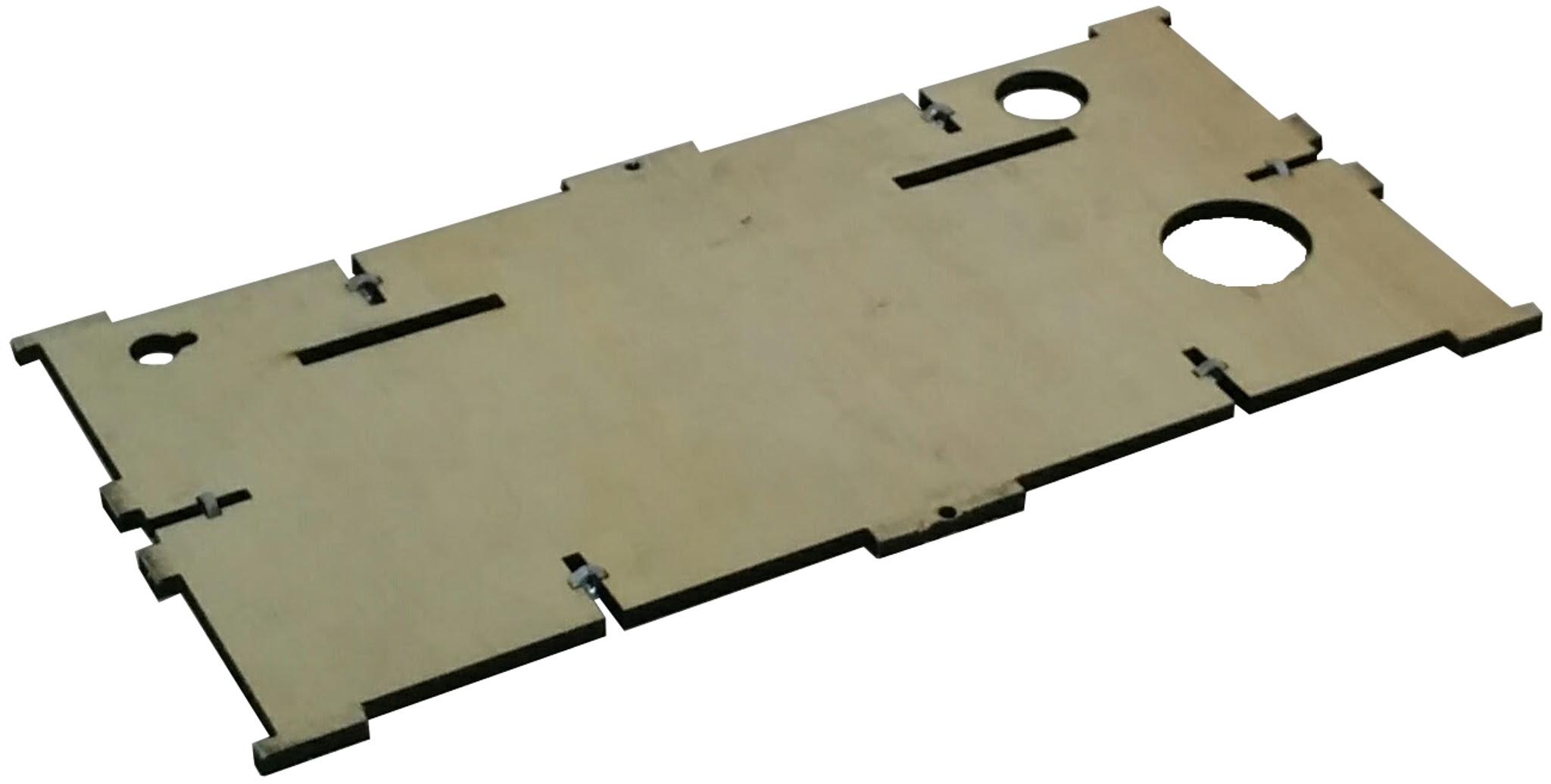
- Place the floor piece on a flat surface with the large holes on the right and slots on the far side as shown below, add the captive nuts to the t-slot. Cover and secure the nuts on the t-slots with masking tape.
Adding the Side Panels
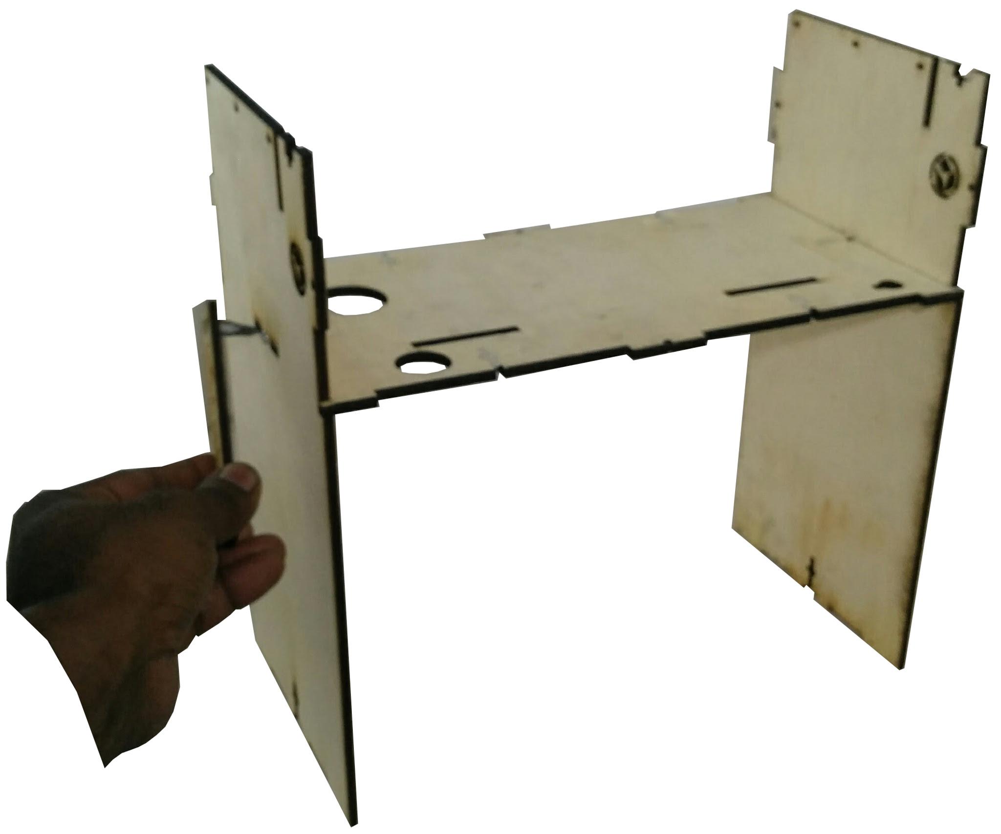
Next, flip the Bottom panel over and attach the Side panels, paying attention to the location of the storyboard slots. Ensure that the slots on the grow-bed floor are oriented in the same direction as the slots at the top of the Sides. Insert and fasten the screw that attaches the grow-bed Floor and Sides together as shown below.
Assembling the Front Panel
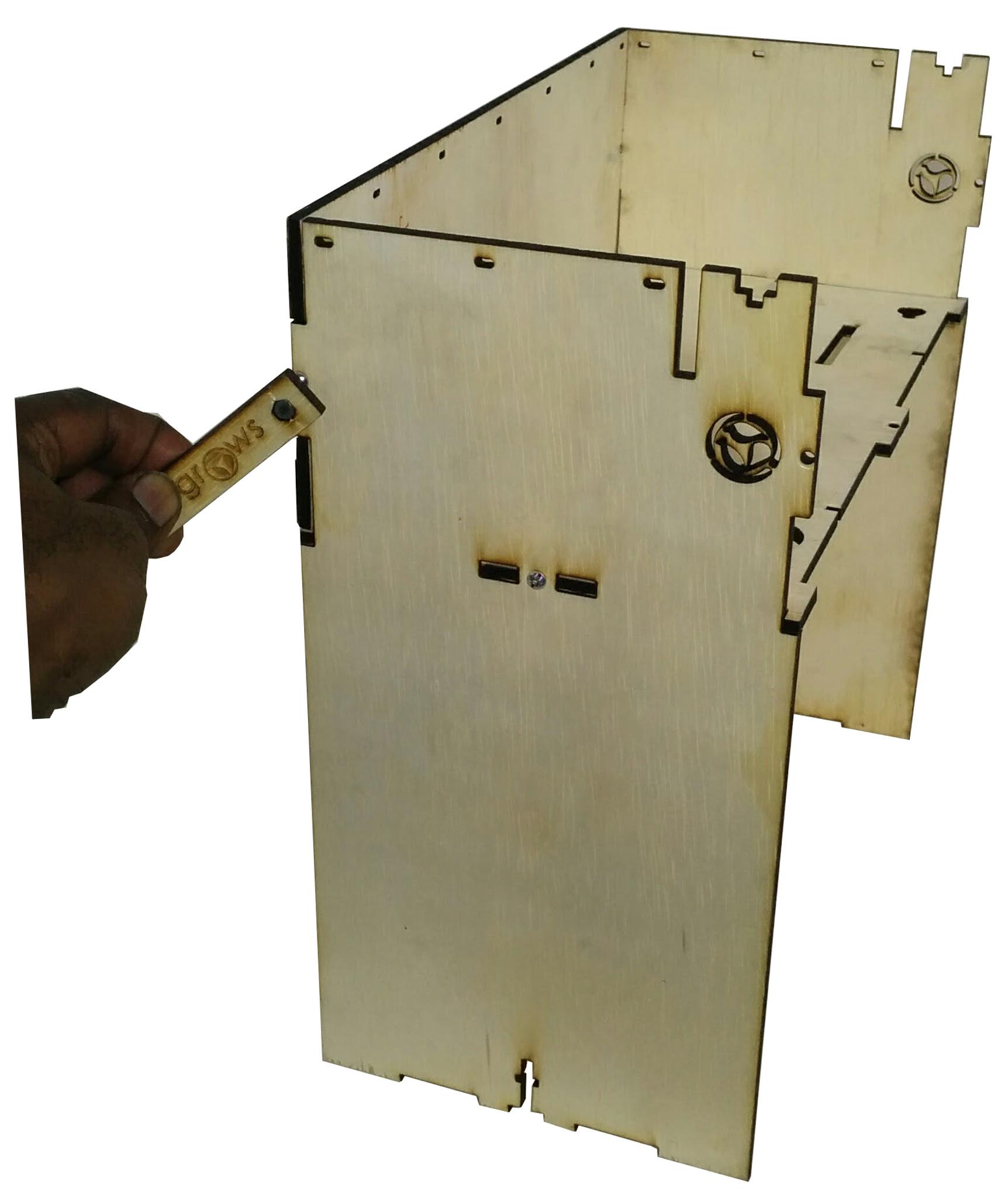
Next we add the Front Face and secure it with the screws onto the base and side panels. Lay the front face on a flat surface and insert the nuts into the t-slot. Hold the nuts in place using masking tape. Attach the Front Panel to the side away from the storyboard slots. Insert the screws through the holes and secure these against the nuts as shown below.
Adding the Story Panel
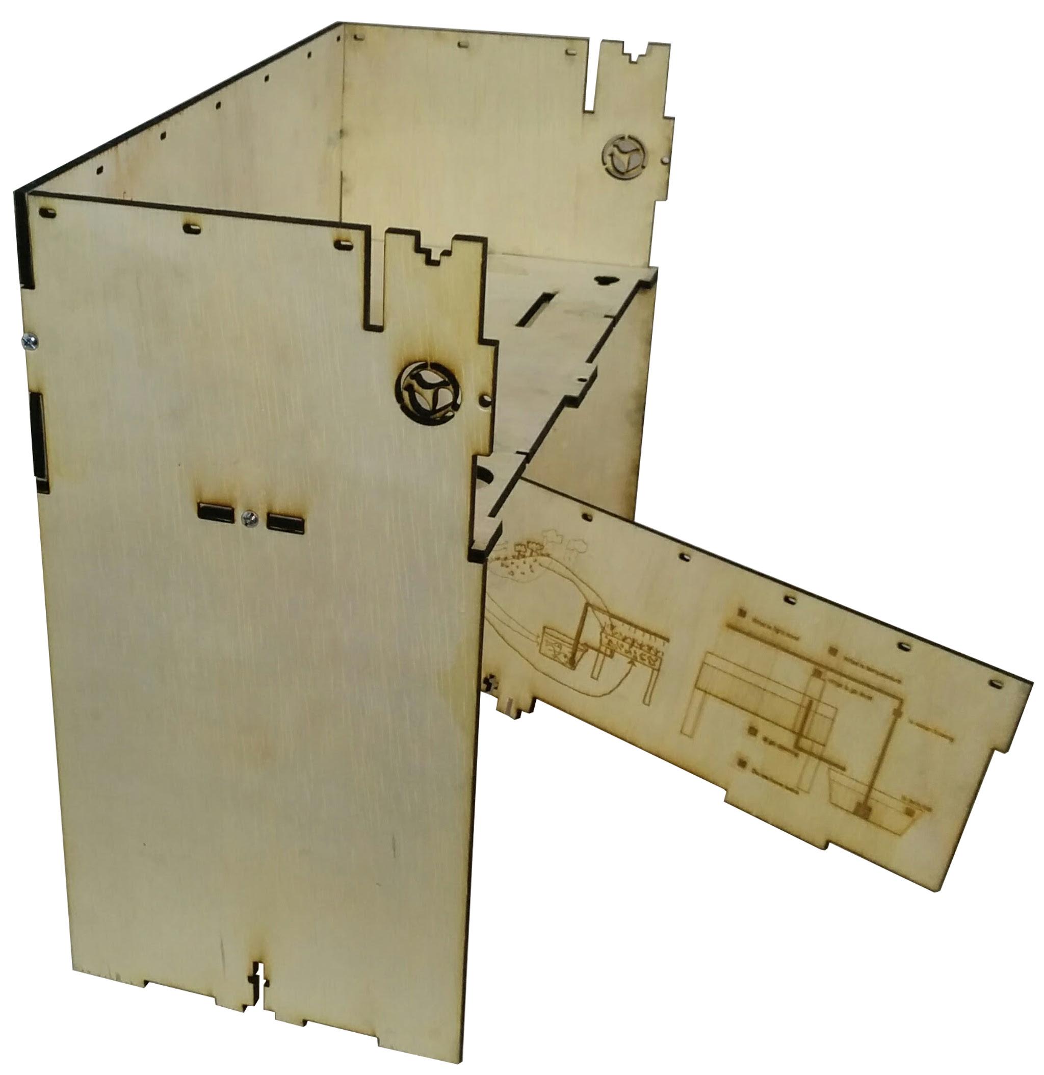
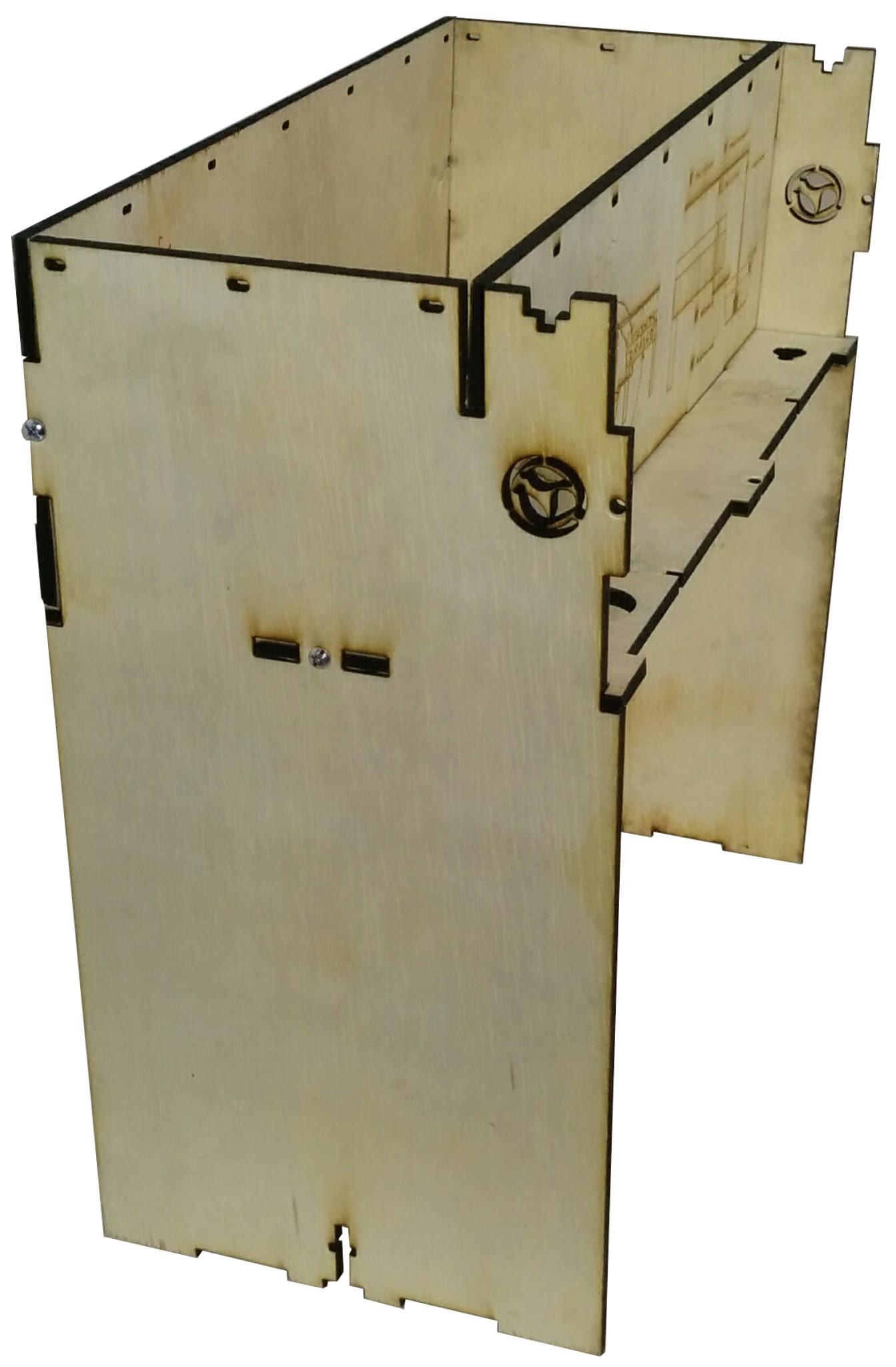
Next we attach the Storyboard Panel to the garden
Assembling the Liner
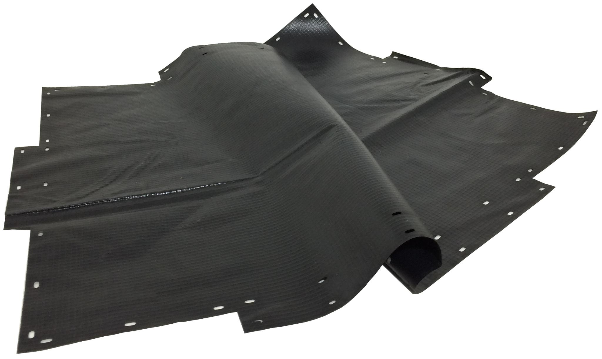
"Important: As you fold the liner, make sure the smooth surface faces out. We will need the rough surface on the inside to help encourage bacteria growth."
Unfold the lining on a flat surface that has no sharp points or edges on it. We will now fold the liner and insert it into growbed. We will be folding the liner in a similar pattern to a common oyster pail and securing it in place with zip ties. We can use masking tape to hold it in position as we make our folds.
Folding the Liner
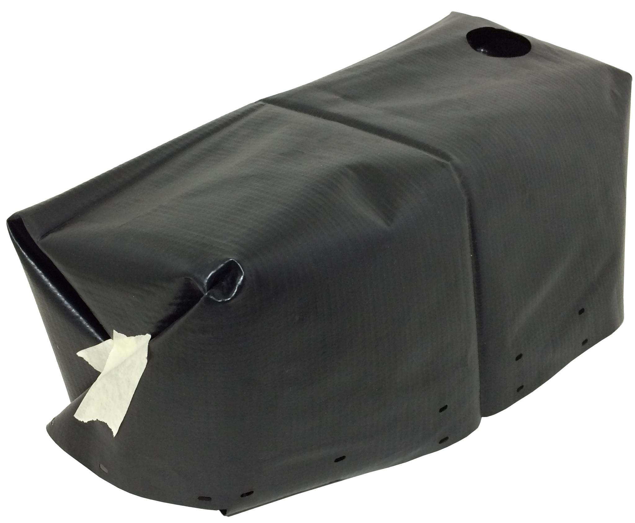
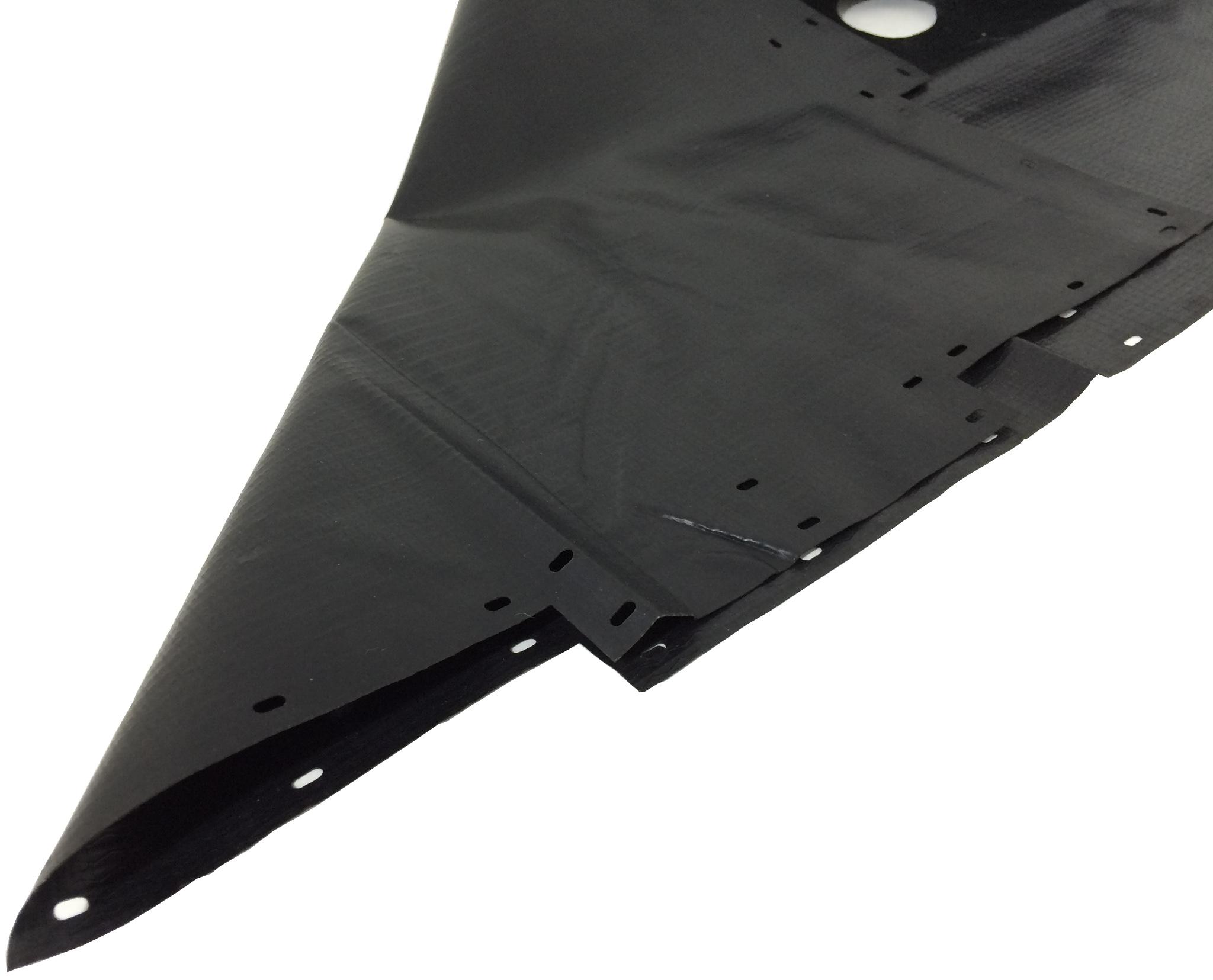
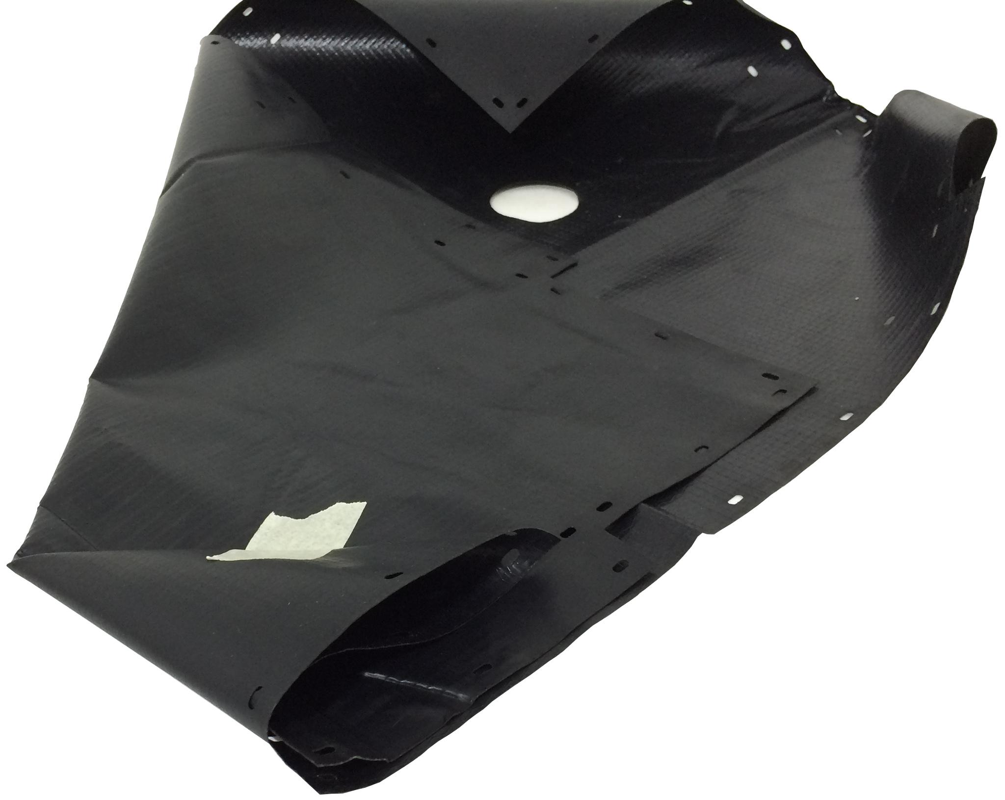
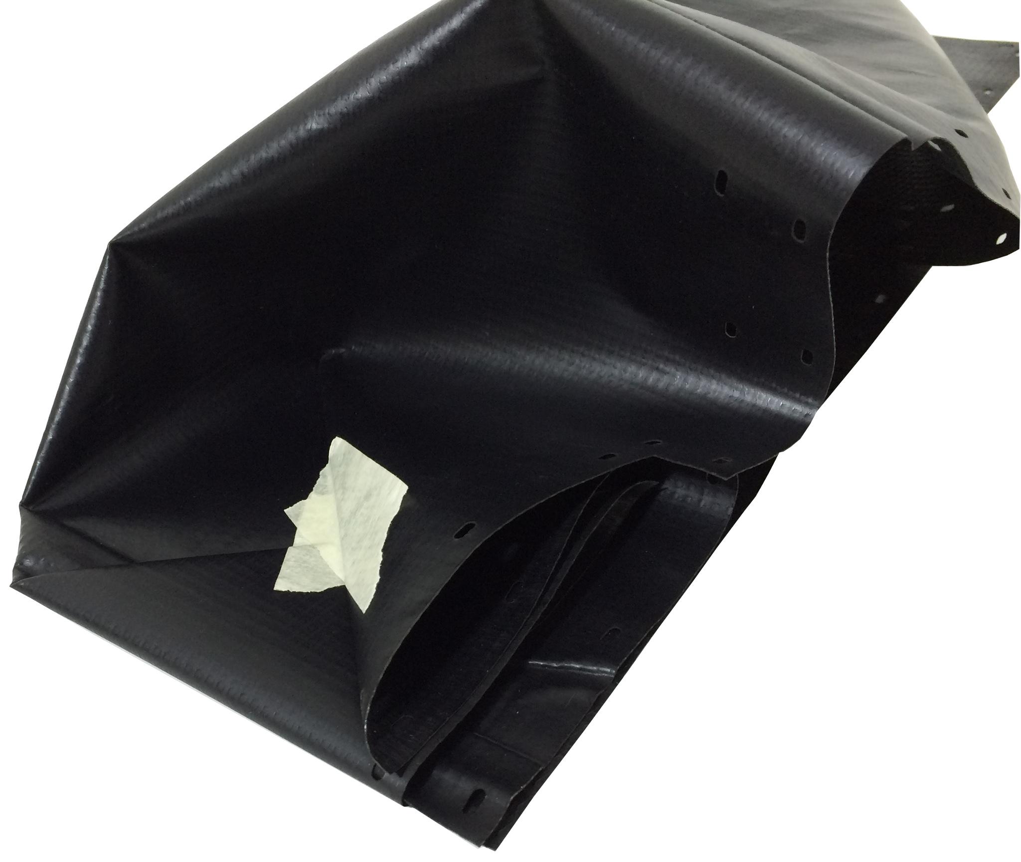
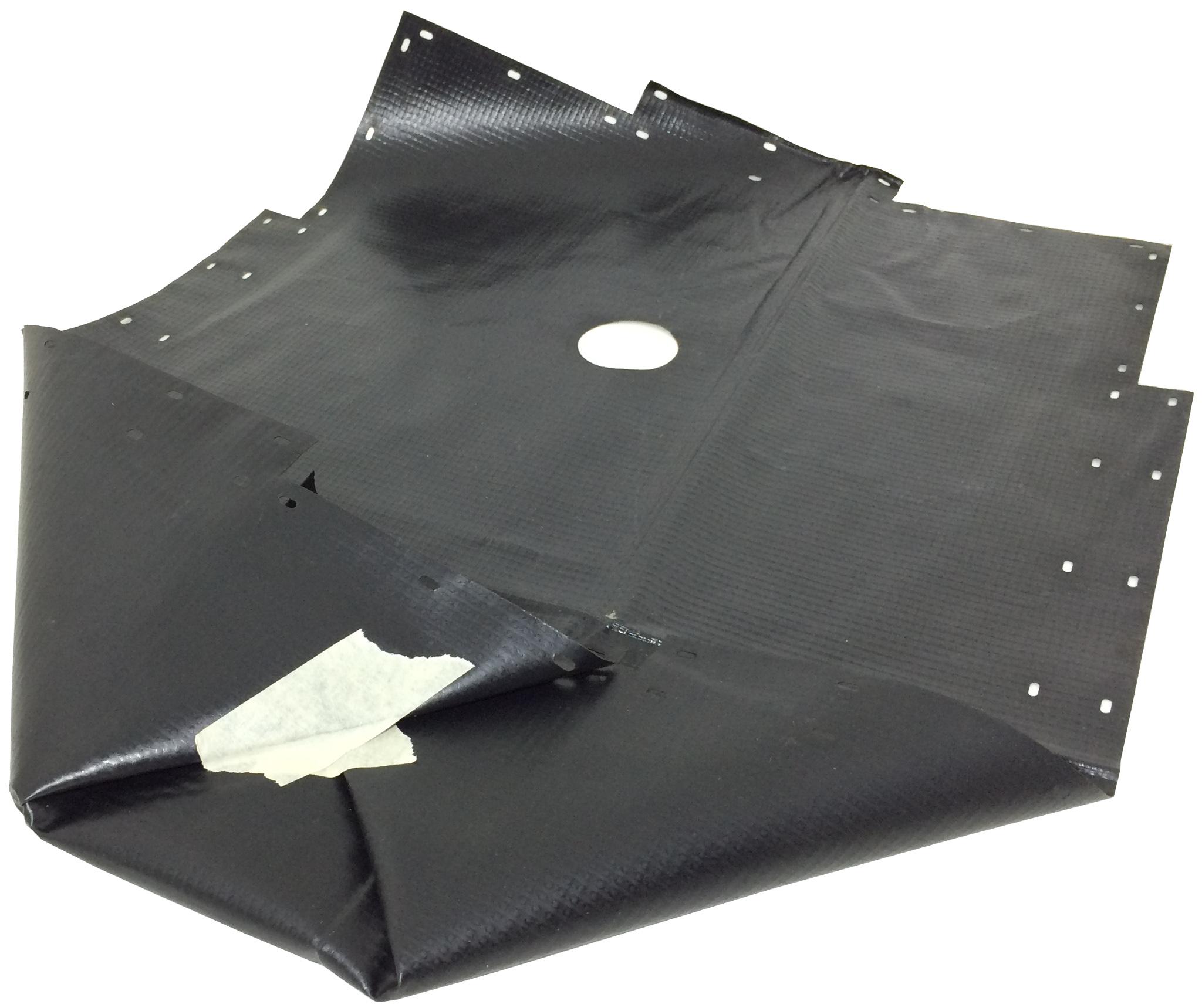
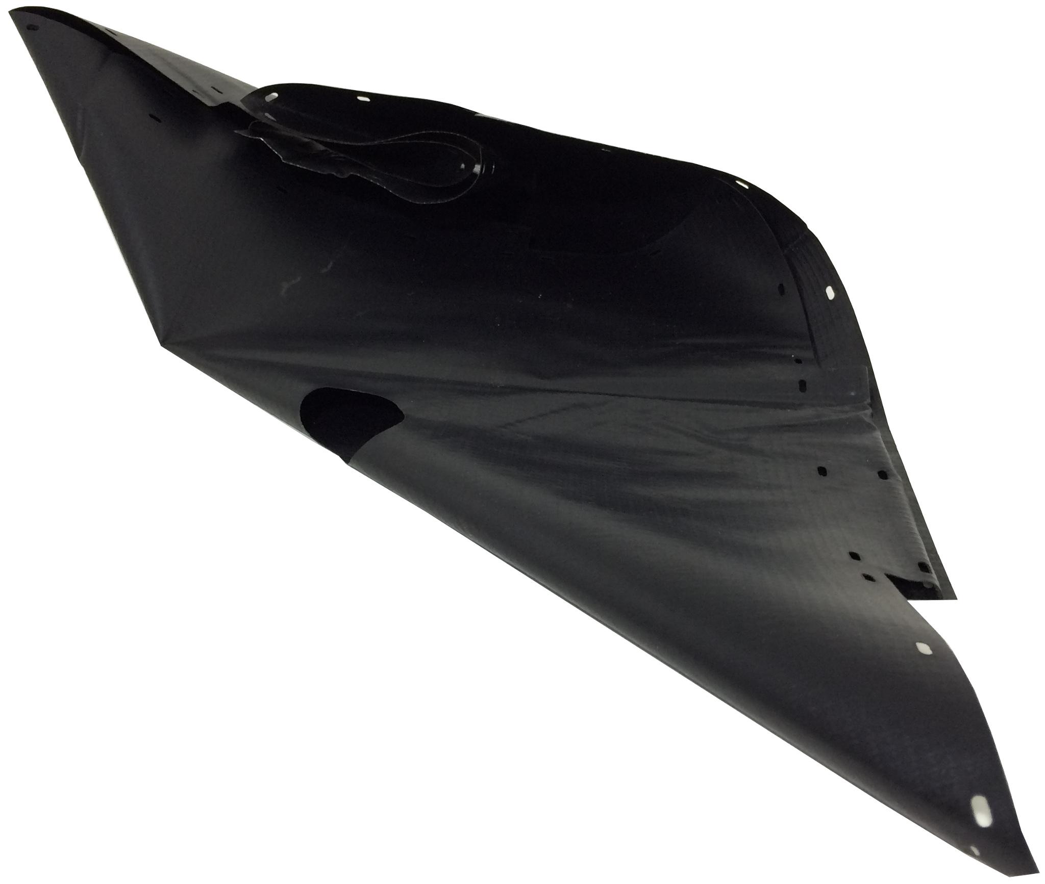

Fold the triangle part over and hold it in place using masking tape, as shown below: Use the pre-cut holes in the liner to align it properly as needed. Next, fold the adjacent corner on the short side as we did the first corner and tape hold both the corners together as shown. Now we fold the other remaining side. Fold one of the corners as shown. Fold the corner in and secure using masking tape as shown. Finally, fold in the last corner and secure both corners together using masking tape. The liner should open up into an open rectangular cube as shown
Mounting the Liner
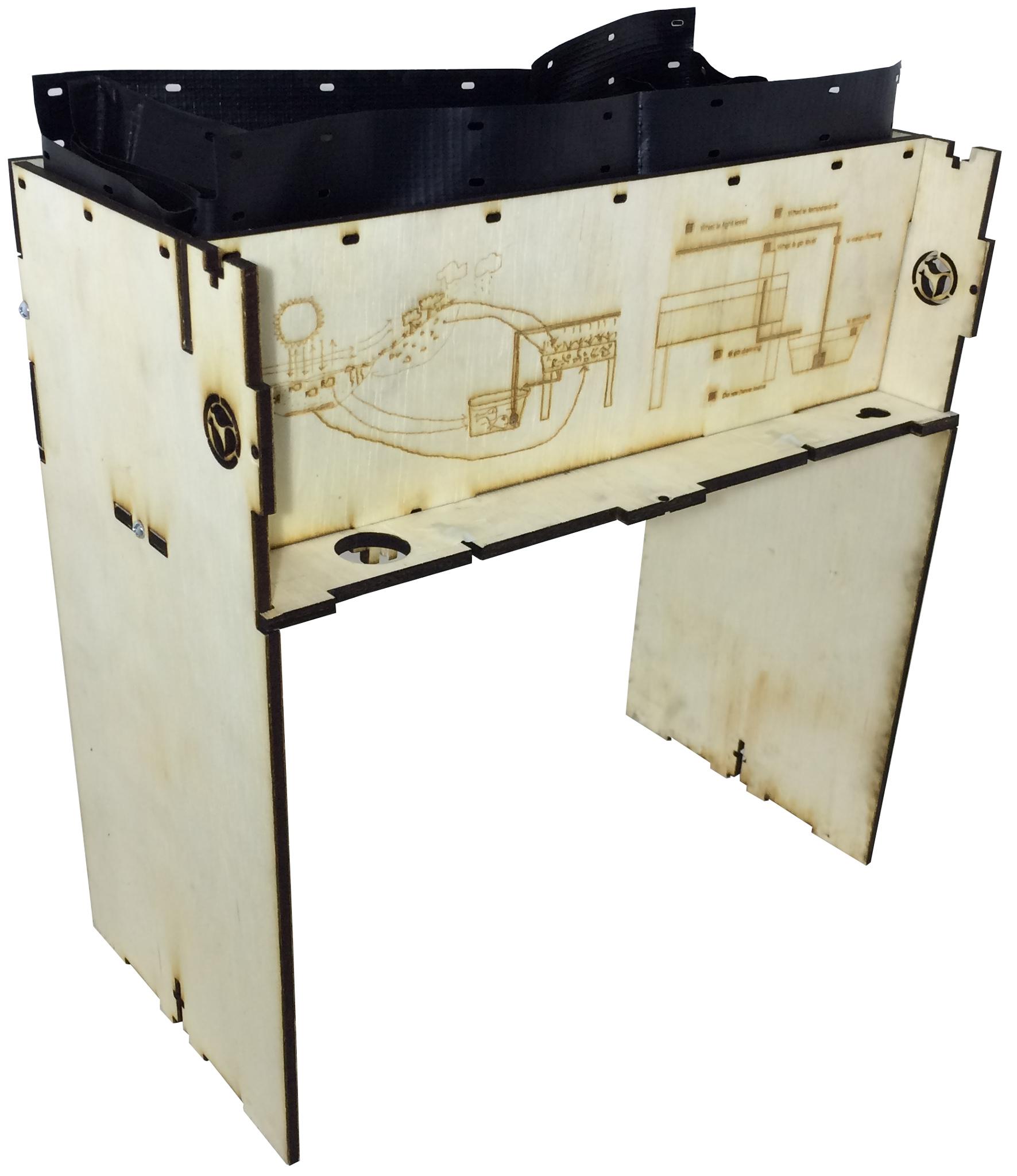
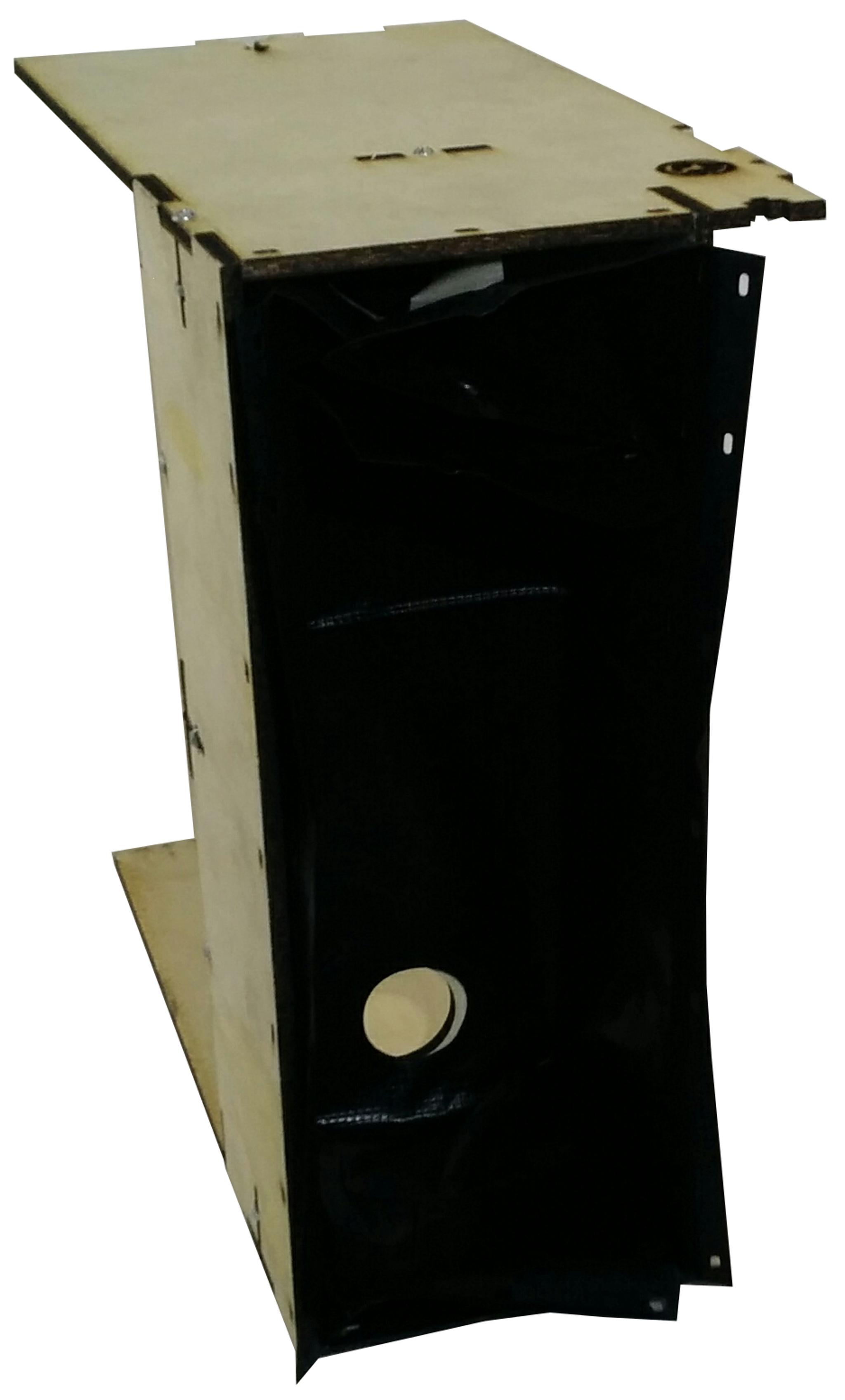
Next, we insert the liner into the grow-bed matching the drainage hole to that on the garden
Securing the Liner
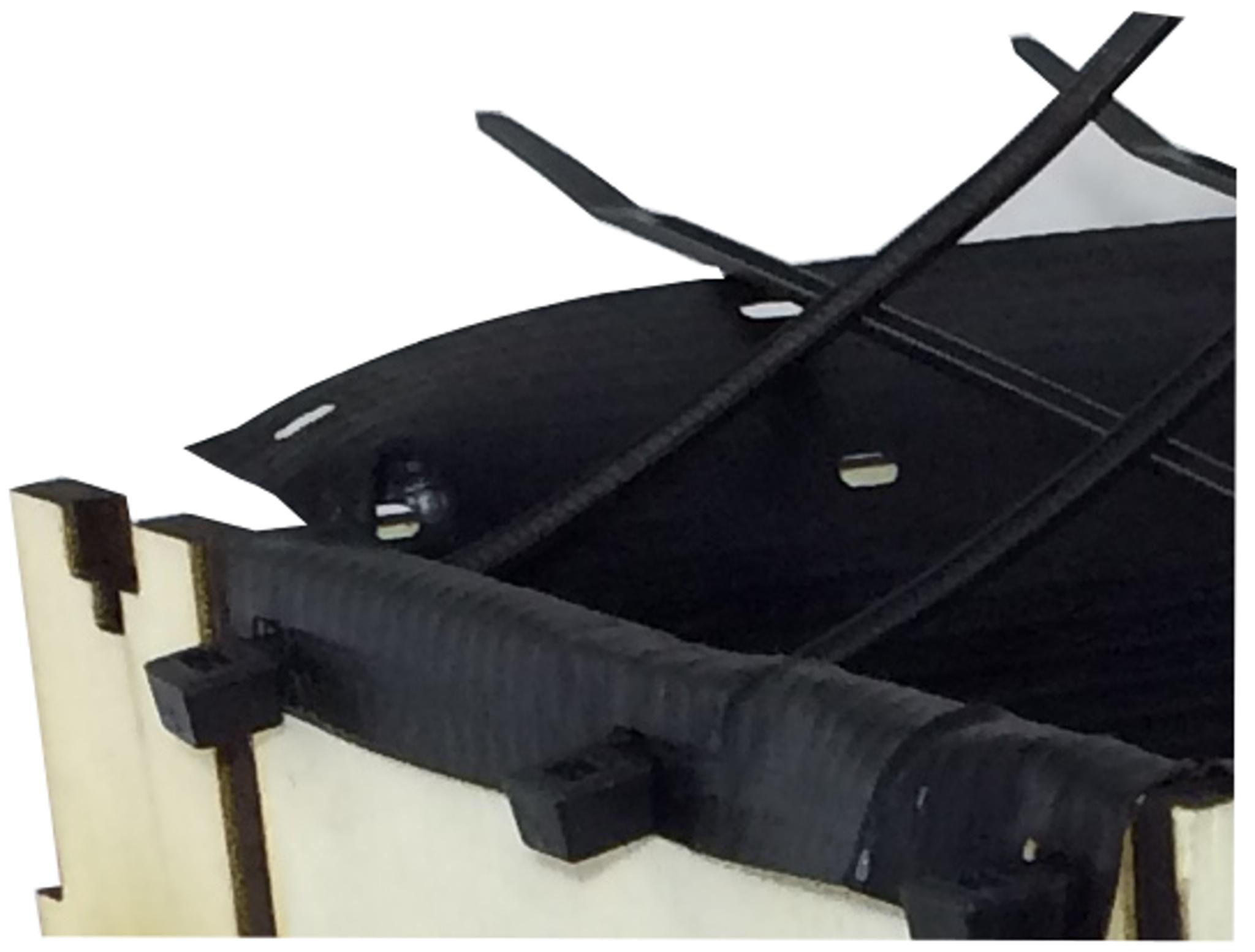
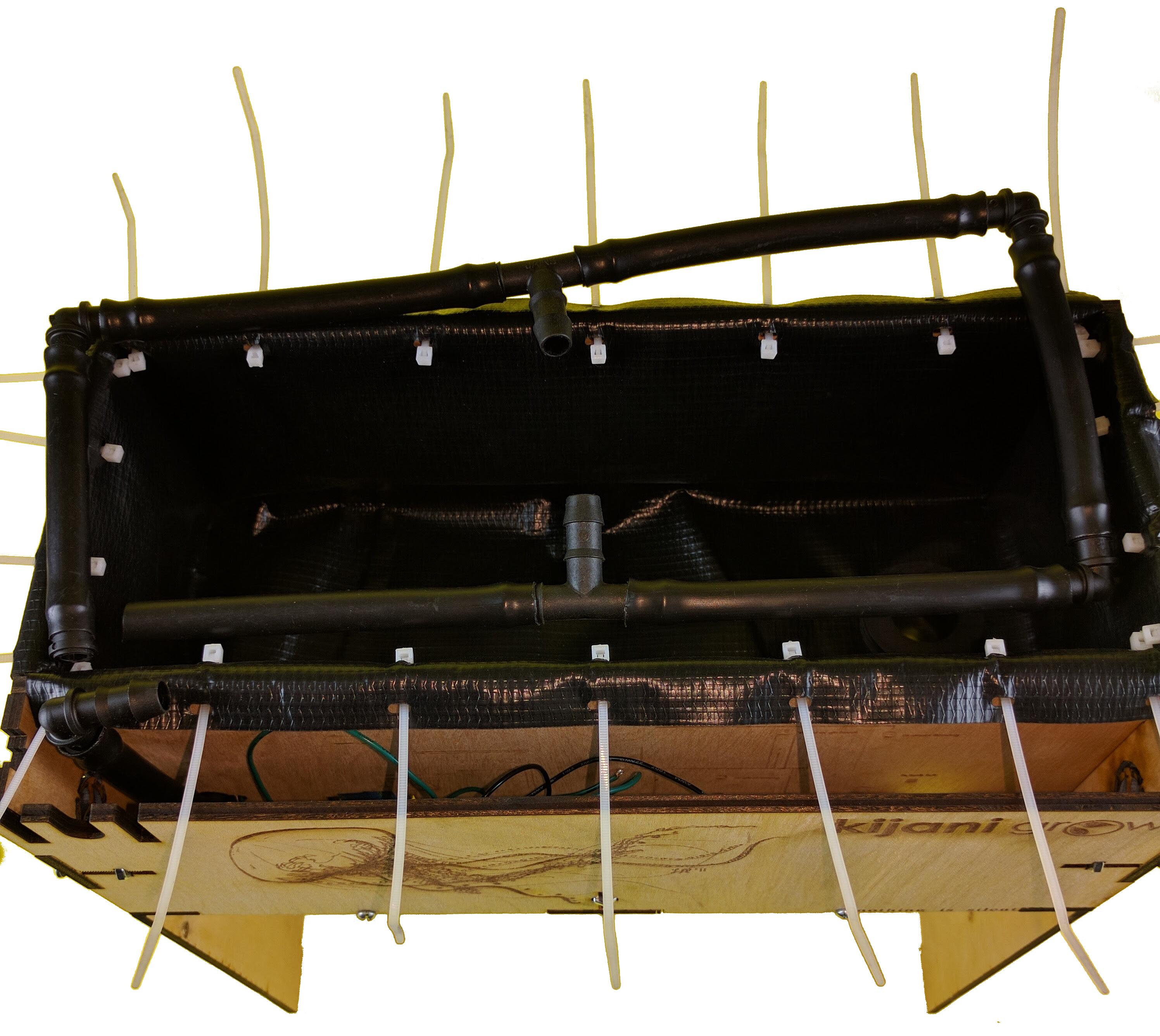
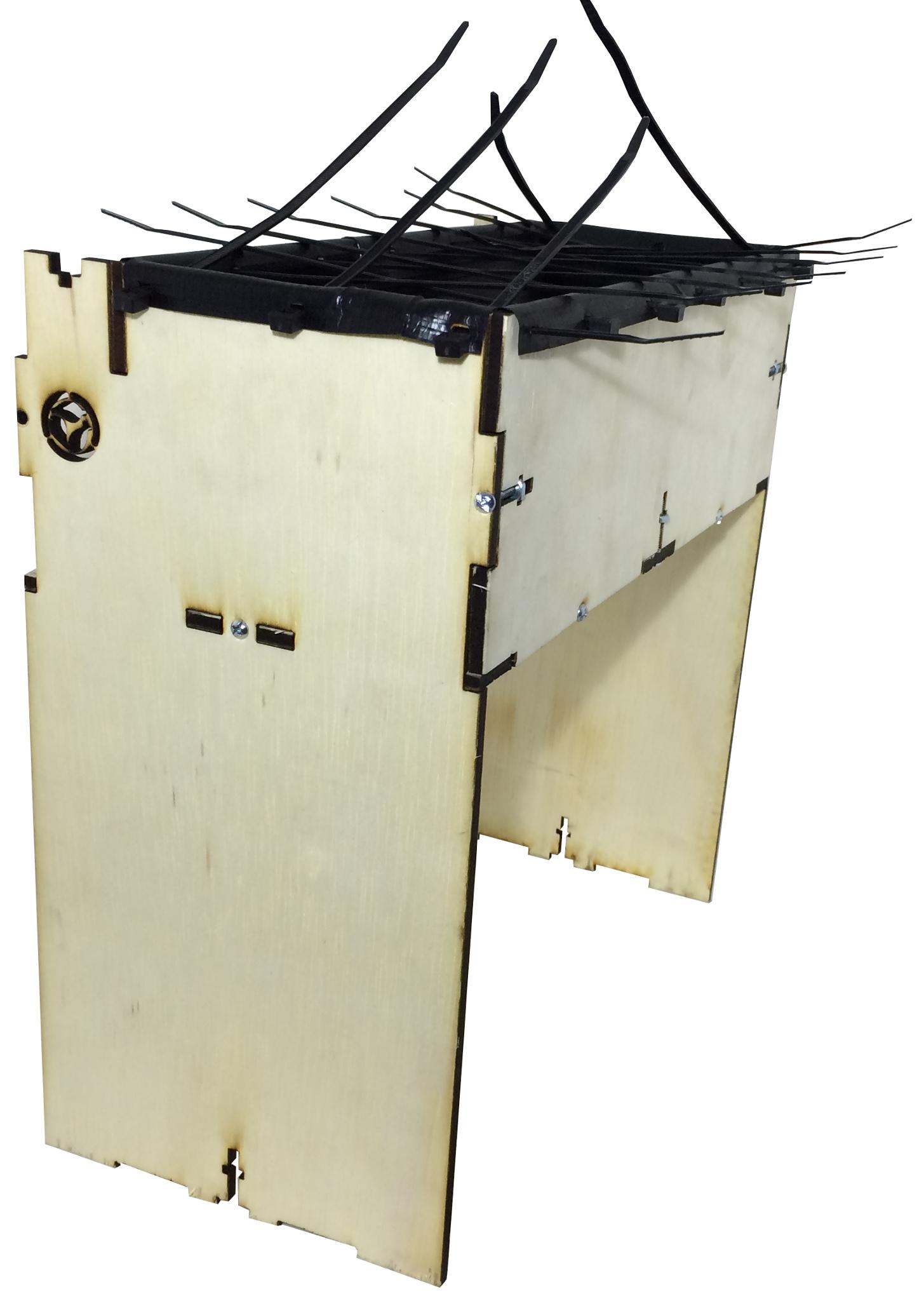
Fold the liner on the outer edge, aligning the zip holes then insert the zip ties through the liner, into the panel, then the outer slots as shown below
Attaching the Drain Kit
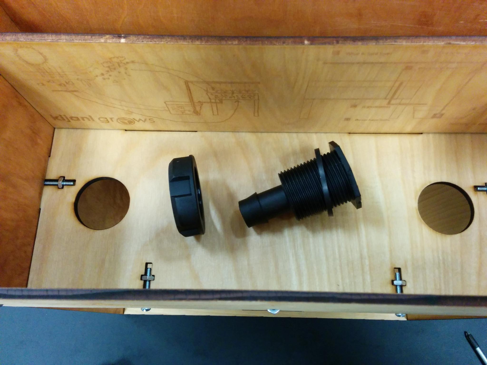
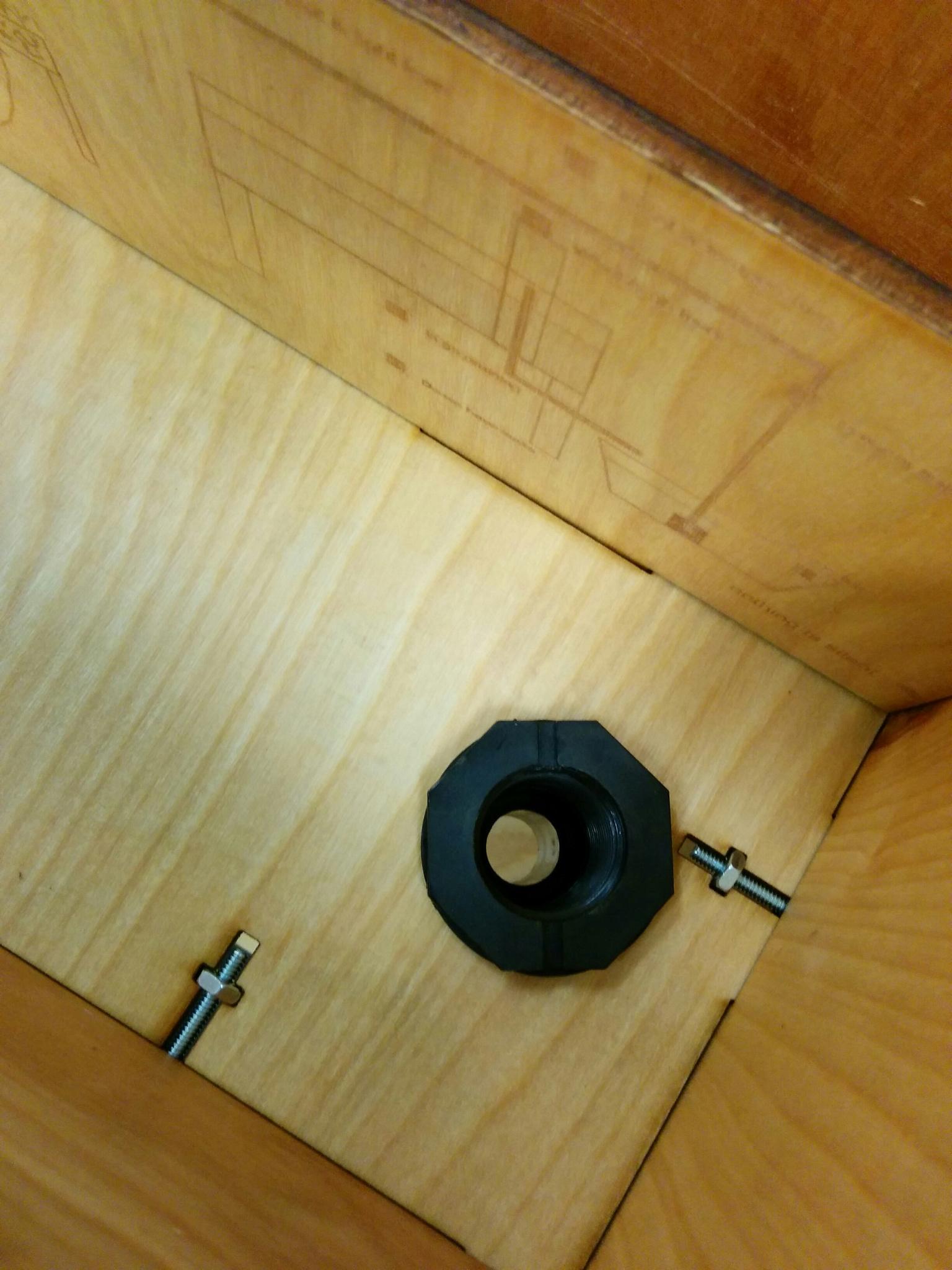
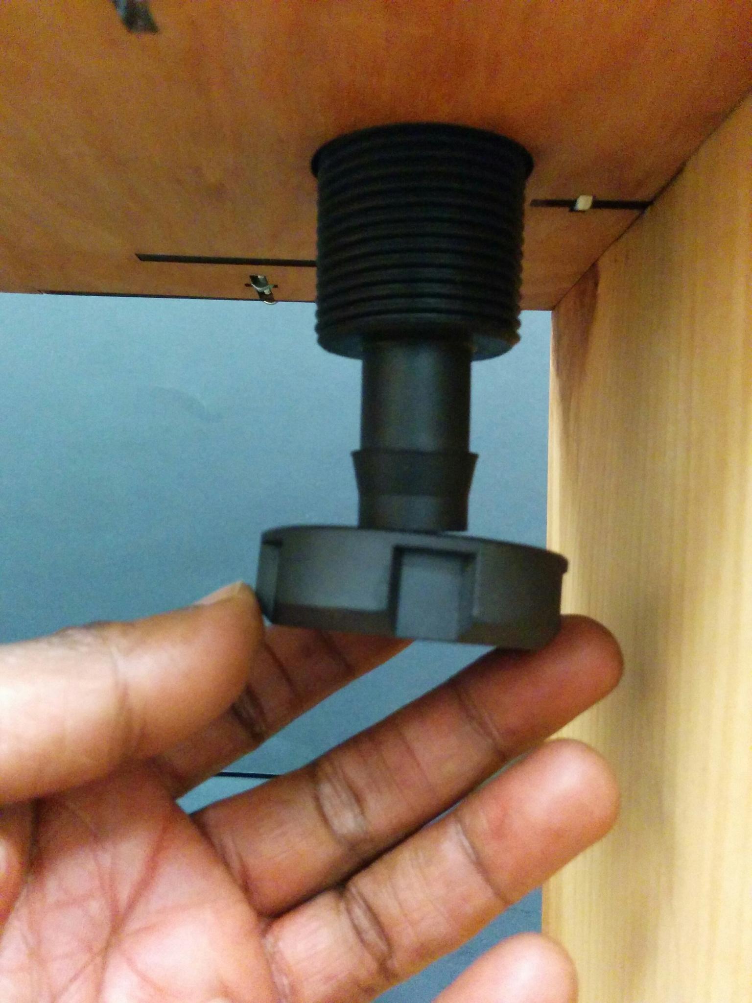
Insert and tighten the bulkhead drainage fittings to secure liner to bottom panel for a watertight drainage as show.
Assembling the Irrigation
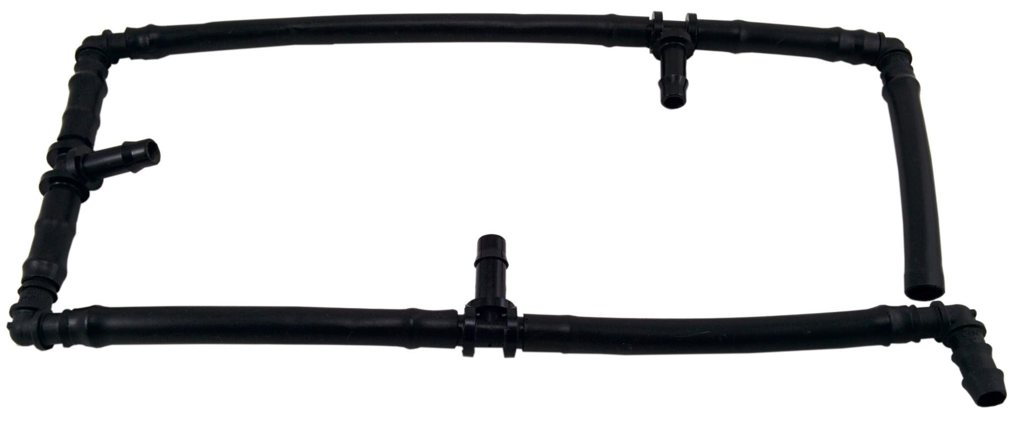
Assemble the irrigation from the tubing and connectors as shown below
Mounting the Irrigation
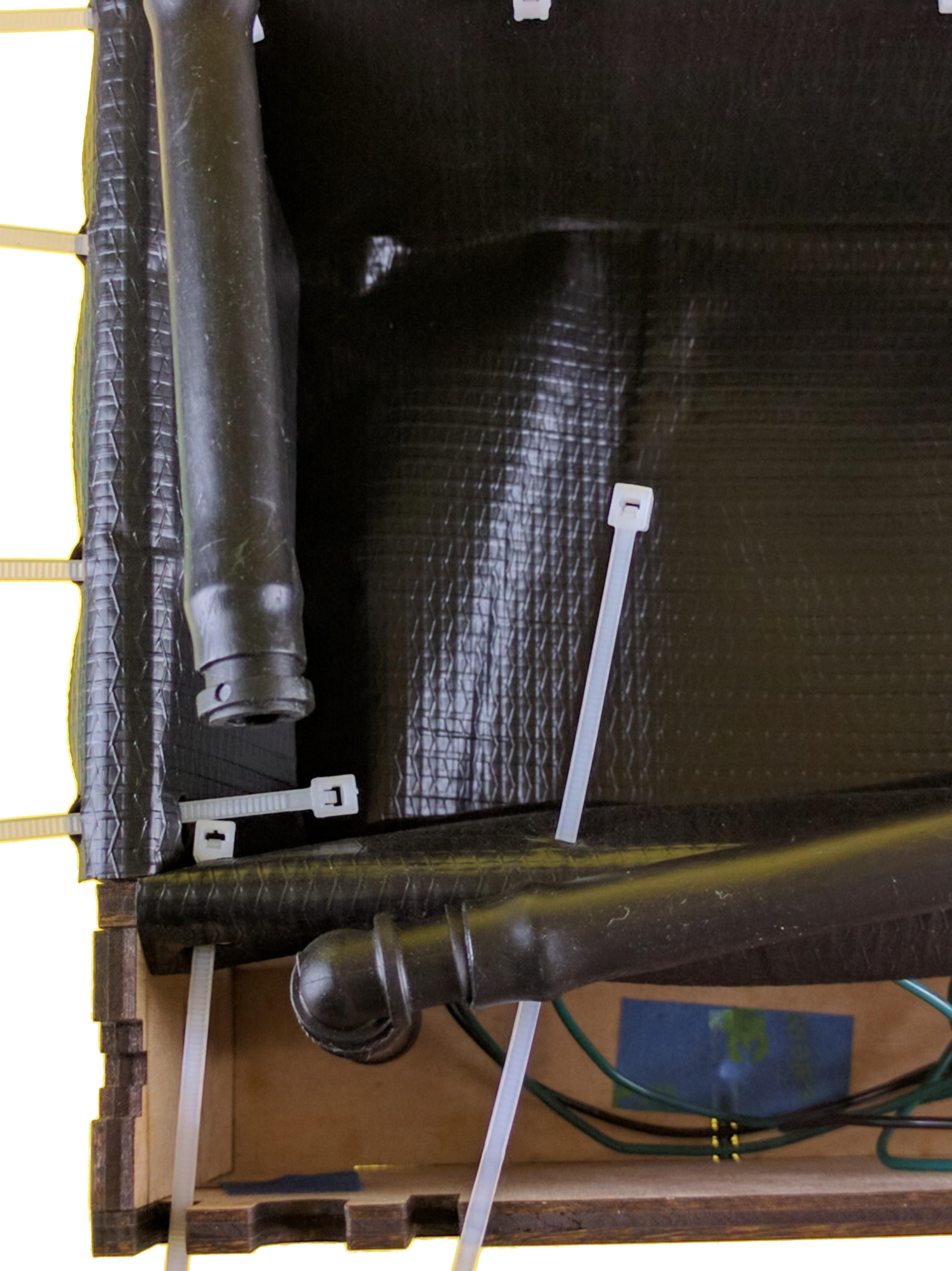
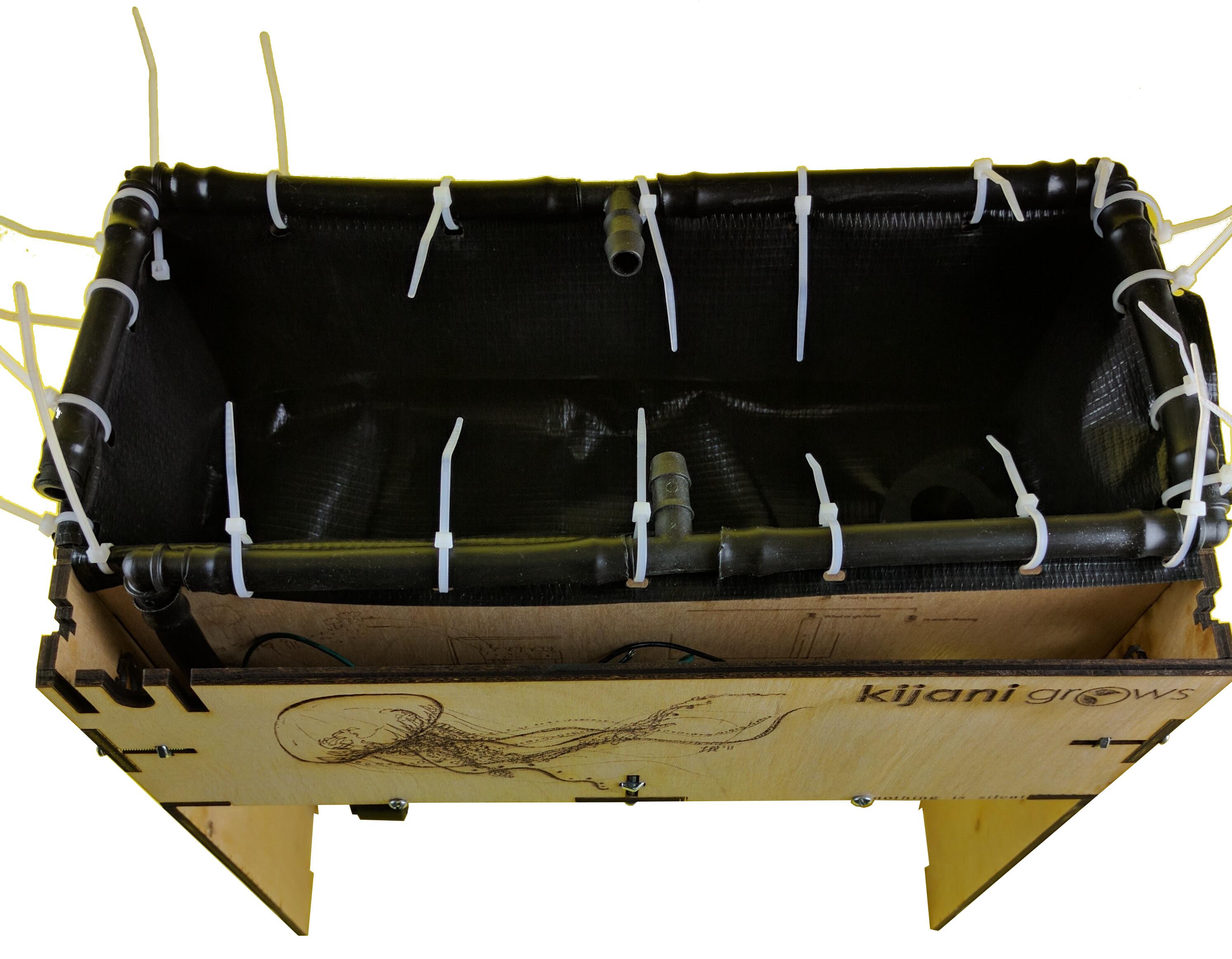
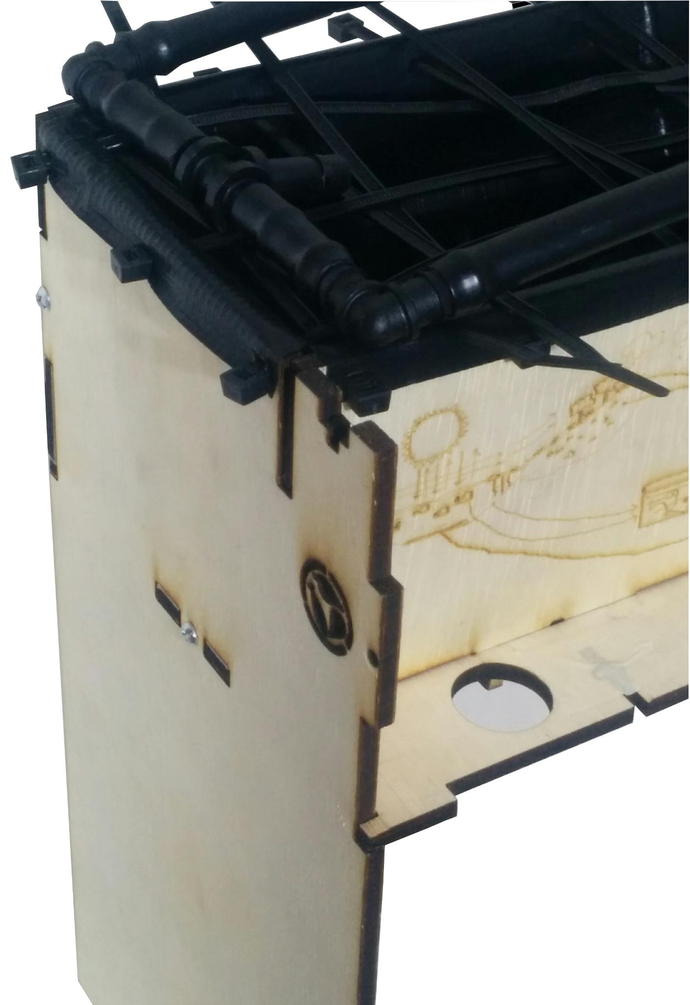
Lay the irrigation tubing on the edge of the liner between the open zip ties as shown below. Orient the elbow nozzle end so it aligns with the pump hole on the base garden panel. Gently tighten the zip ties around the irrigation tubing and snip off the ends for a clean finish as shown.
The V2 Controller
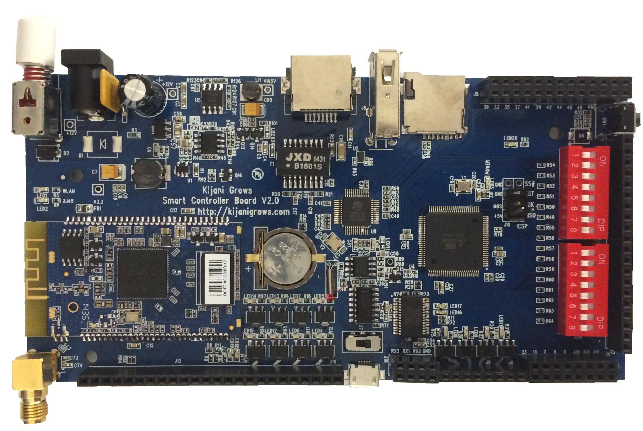
Now that the sensor box, tank sensor adapter, and capacitive level sensors are ready, we can begin wiring them to the v2 smart controller. The v2 controller board is shown.
Protecting the V2 in the Cardboard Enclosure
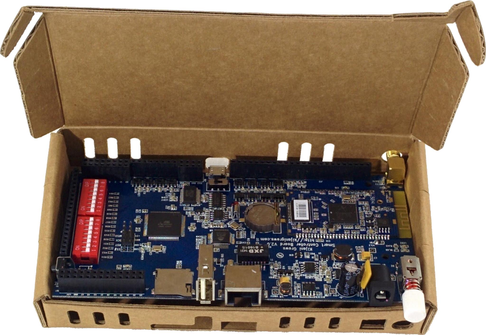
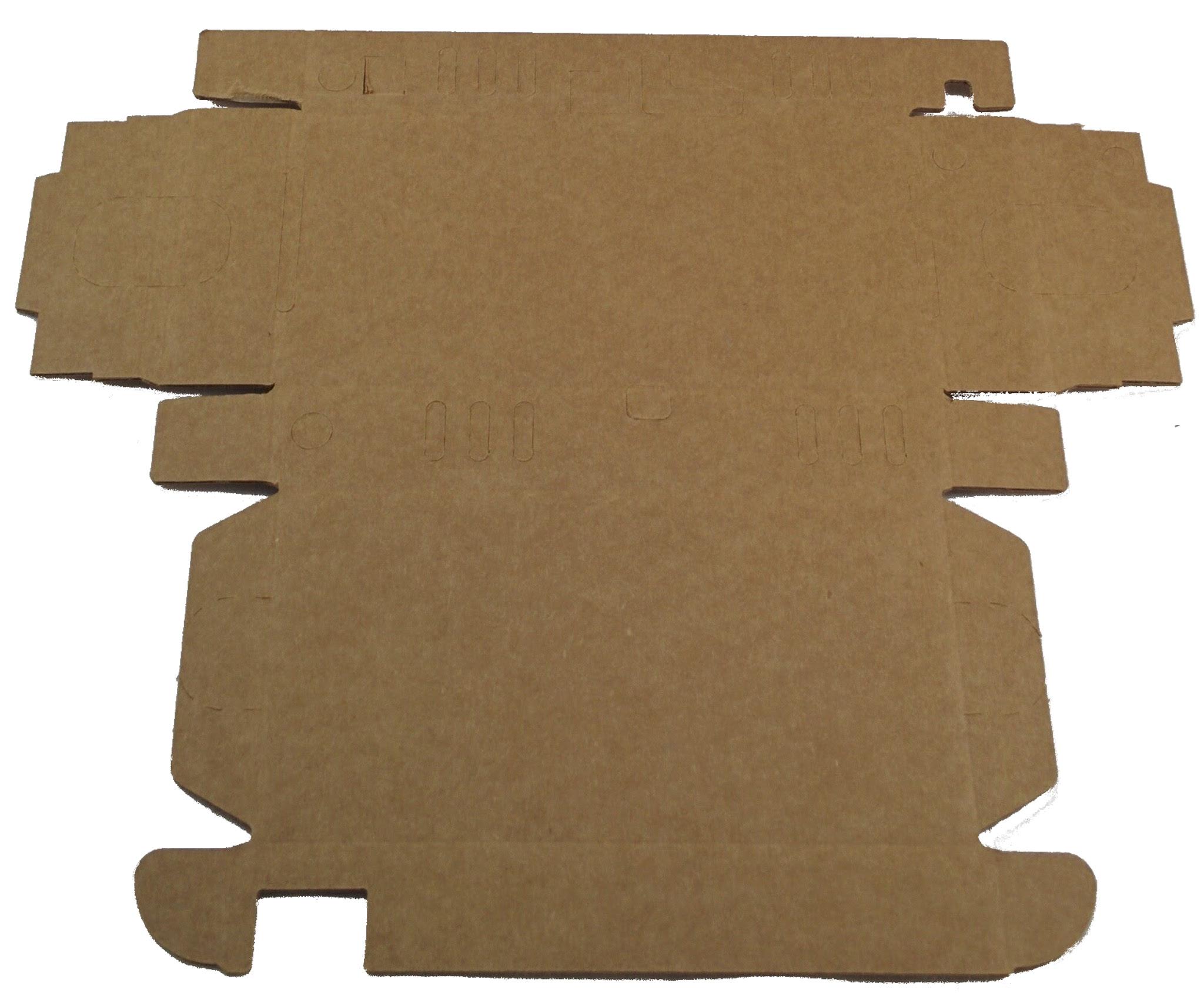
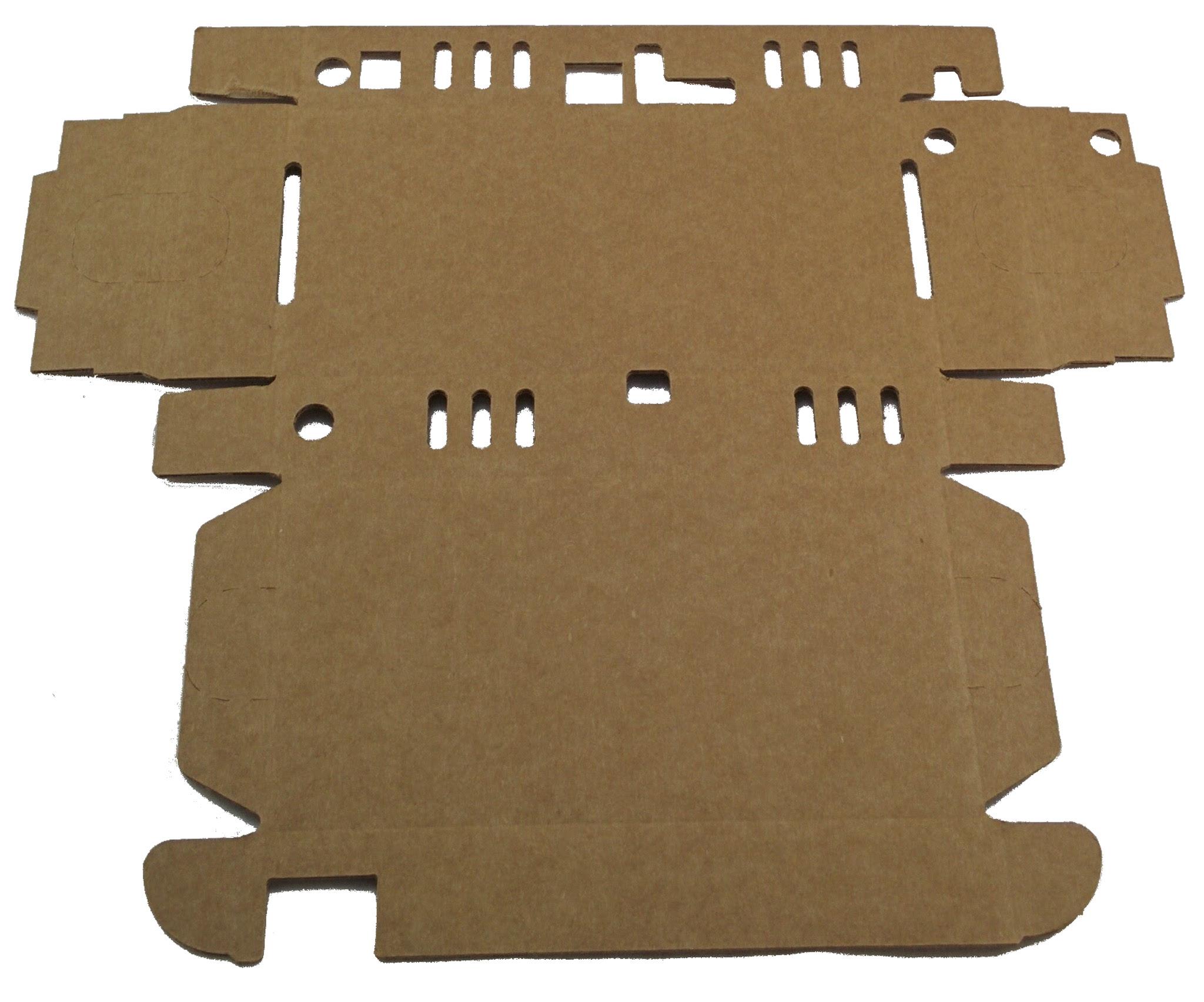
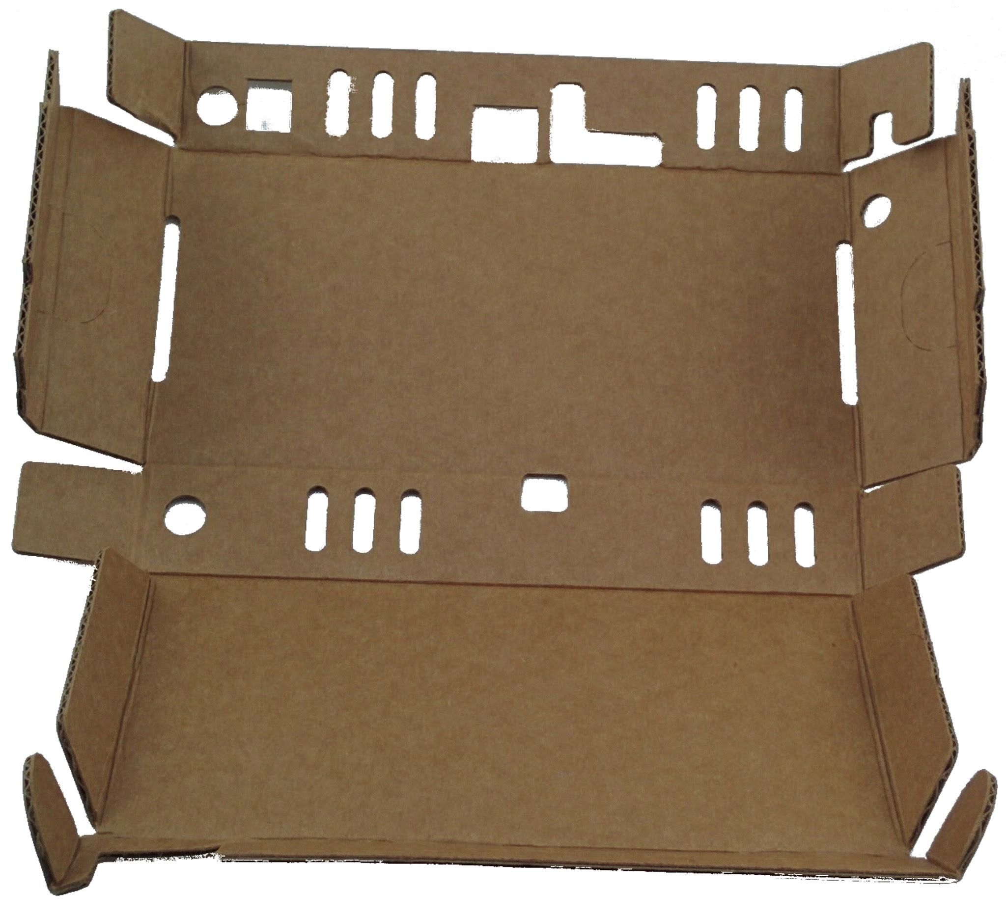
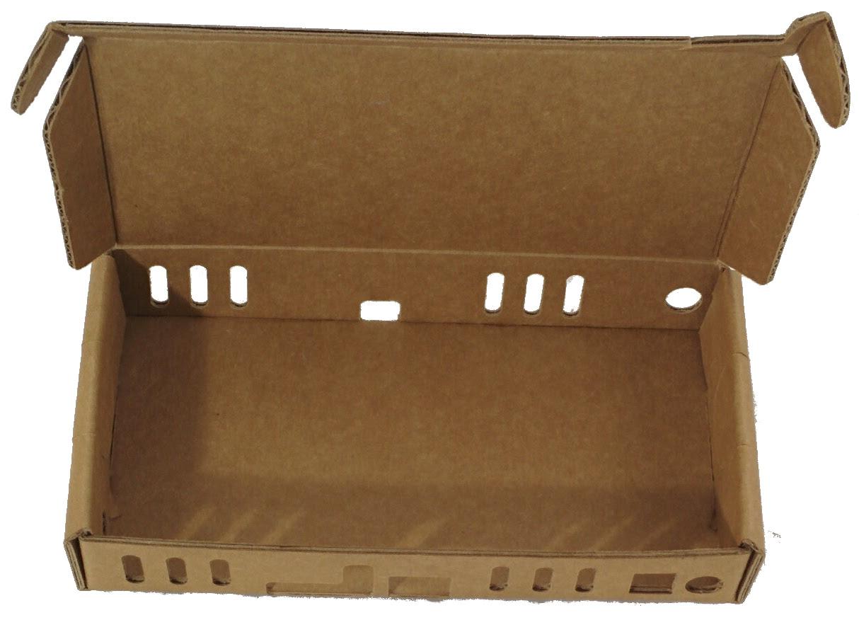
The first step is to protect your board using the v2 cardboard enclosure. Knock off the cutout holes. Pre-fold the enclosure hard along its score lines. Watch out for the following delicate corner. Fold and lock the cardboard enclosures flaps to complete the enclosure. Insert the v2 board to the enclosure starting from the antenna side
Connecting the V2 Controller
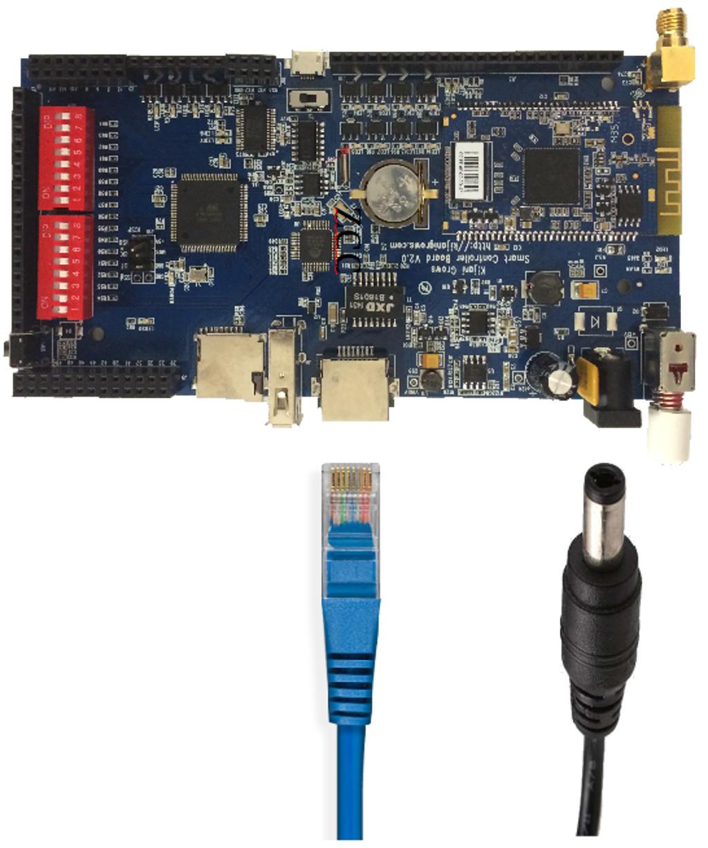
Connect the v2 controller to your laptop using Ethernet as shown
Powering the V2 Controller
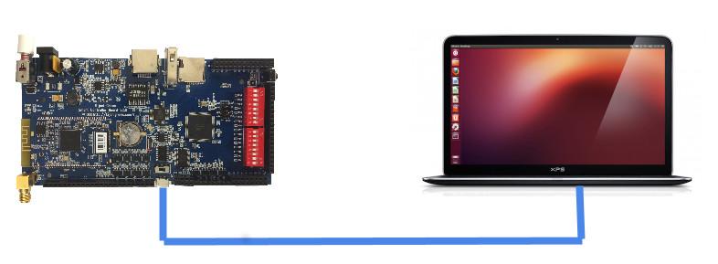
Power the v2 controller by depressing the white power button. Your computer will be assigned an ip address 192.168.73.x by the v2 controller if it is DHCP enabled
Connecting to the V2 Controller
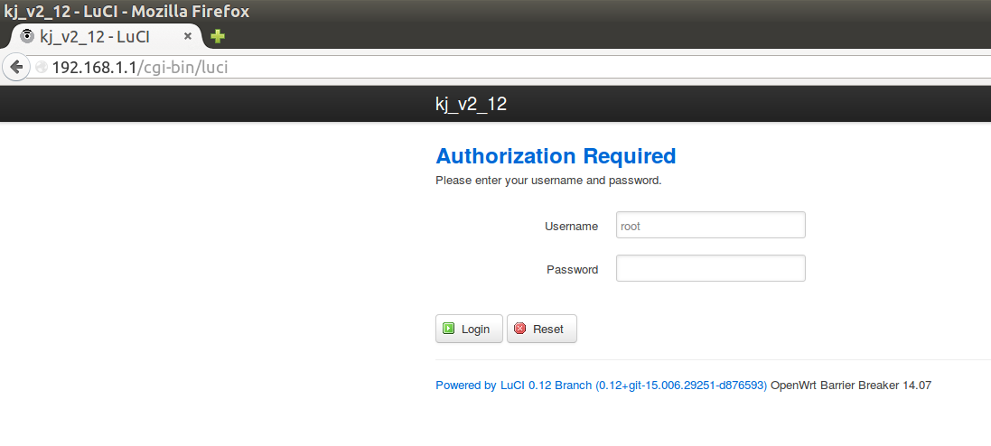
Using an internet browser, point your browser to the dhcp assigned network by entering the url http://192.168.73.1 and press the return button. Using an internet browser, point your browser to the dhcp assigned network by entering the url http://192.168.73.1 and press the return button. Login with the username ‘root’ and password ‘tempV2pwd’
Setting a Unique Hostname
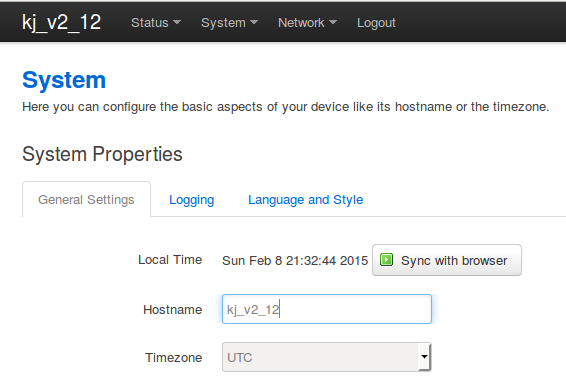
On the System menu bar, click on 'System' from the dropdown list. On the System menu bar, click on 'System' from the dropdown list. You can optionally change the default board name and timezone here. Type in the new device name in the 'Hostname field. You can change the Timezone here as well. Click 'Save & Apply'. Depress the power switch Off/On for the new hostname take effect.
Configuring WIFI
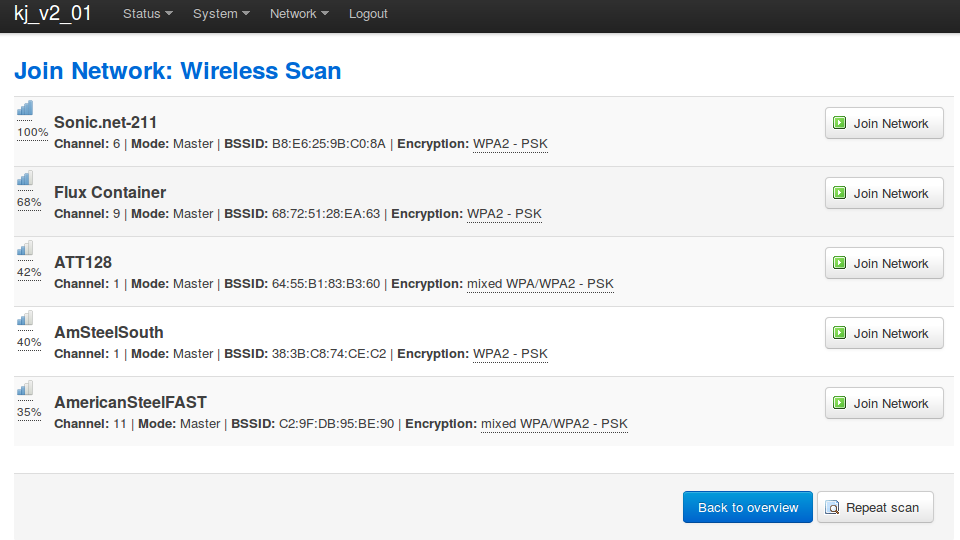
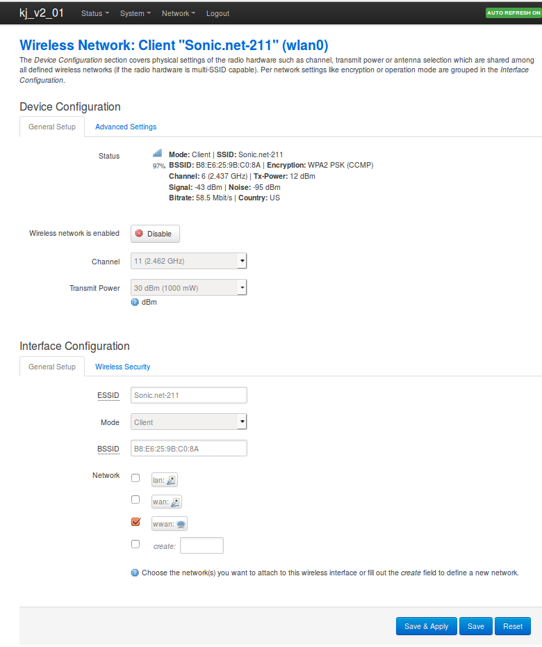
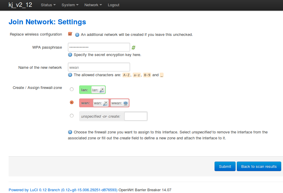
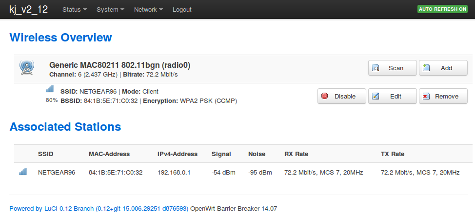
While still connected using Ethernet and DHCP. Access the v2 client using the URL http://192.168.73.1. Select the 'Network' from the menu, then select Wi-Fi from the drop-down list as shown. On the Wi-Fi, menu, click on the 'Scan' button and select your Wi-Fi Network from the list using the 'Join Network' button as shown. Enter the security credentials for your network, click the Submit button. The status wireless icon should turn blue and indicate the strength of the connection. Click on 'Save & Apply' to complete the Wi-Fi configuration. Confirm your Wi-Fi connection using the status menu. From the 'Status' menu, select the 'Overview' option. Ensure you have an IP address In the Network section. Double-check your Wi-Fi Security credentials if the controller did not make a connection in the Wireless Security tab shown above
Registering Your Device Remotely
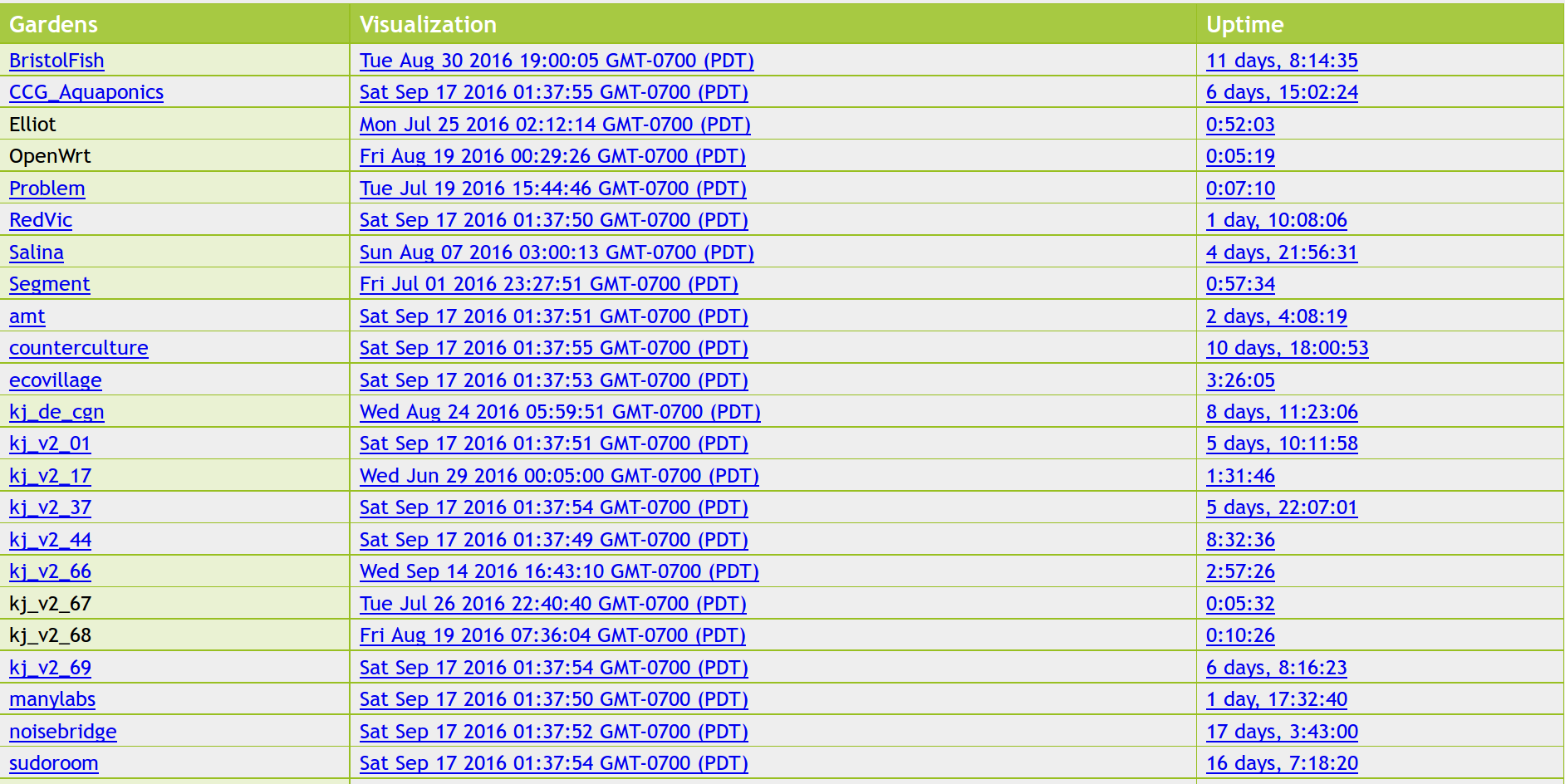
In a browser, navigate to http://api.kijanigrows.com/v2/devices/yourDevice. You should see your device name in the device list as shown below. It should appear without any color on the name, and the time fields should increment every few seconds. If not, double-check your device Hostname and Wi-Fi connection.
Assembling the Sensors
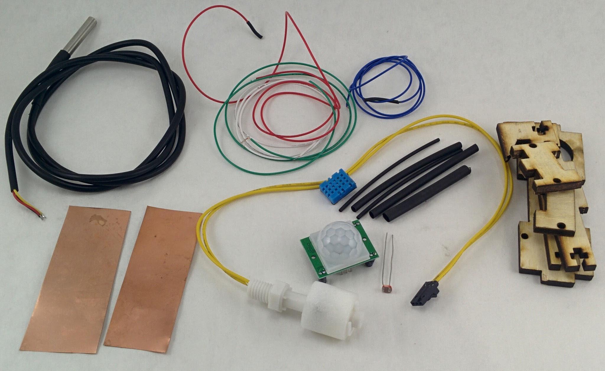
We will now build our sensor box and mount sensors on this. The sensor box and components parts are shown below:
The following are the sensor kit parts:
- Sensor box
- Humidity / ambient temperature sensor
- Proximity sensor
- Light level sensor
- Fish tank float level sensor
- Water temperature sensor
- Capacitance growbed sensor
- Wires
- Heat shrink tubing
- Screws and bolts
The Sensor Box
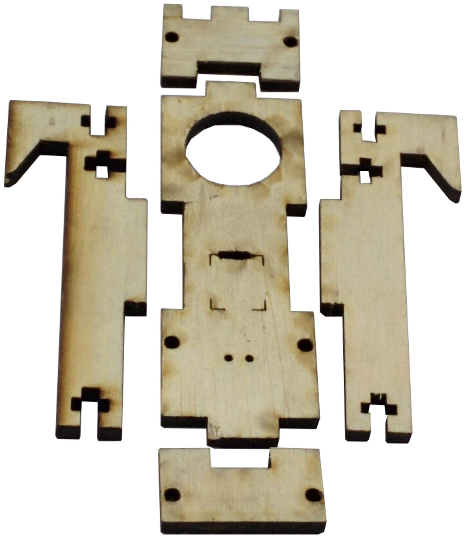
The sensor box parts are show
Environmental Sensors
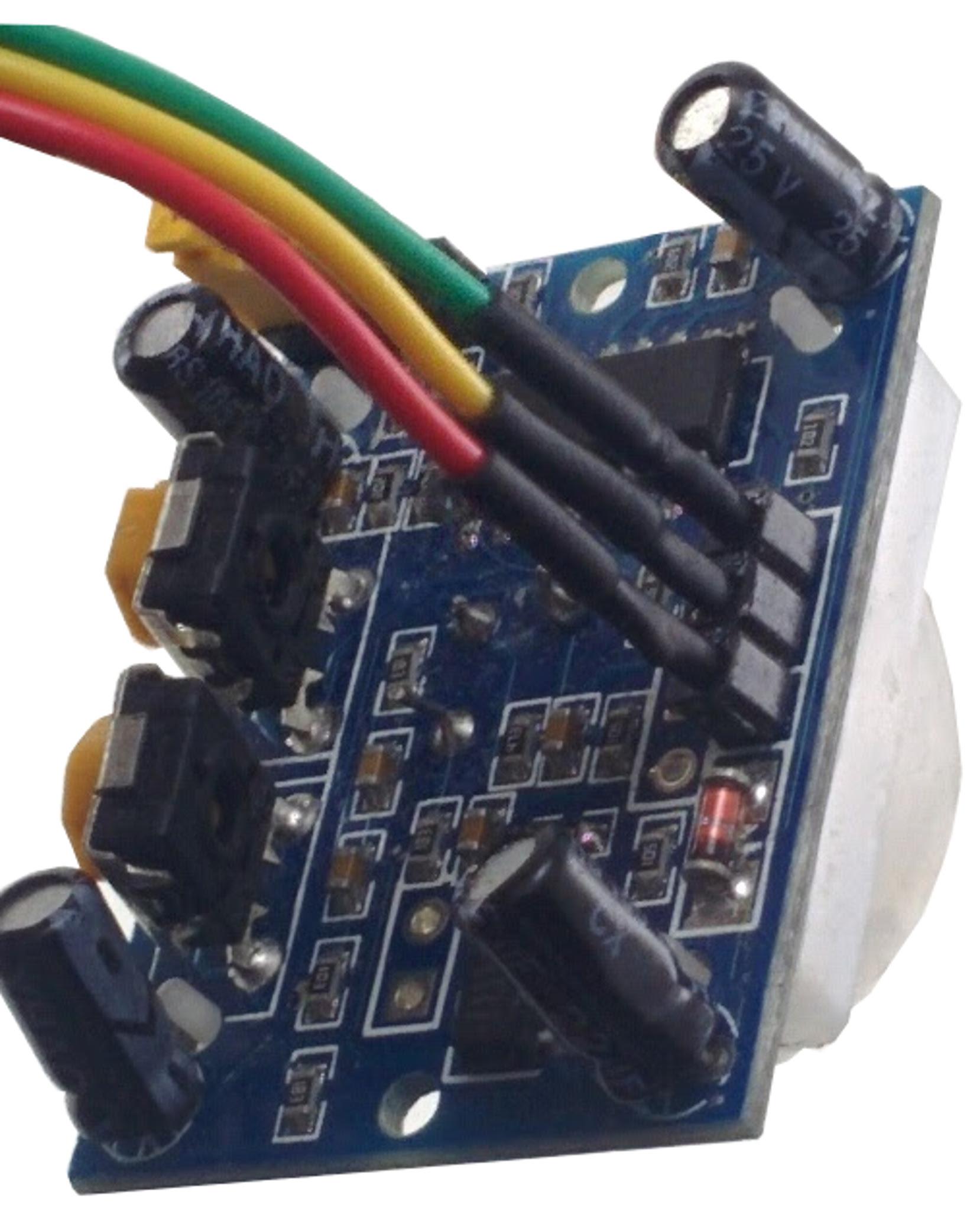
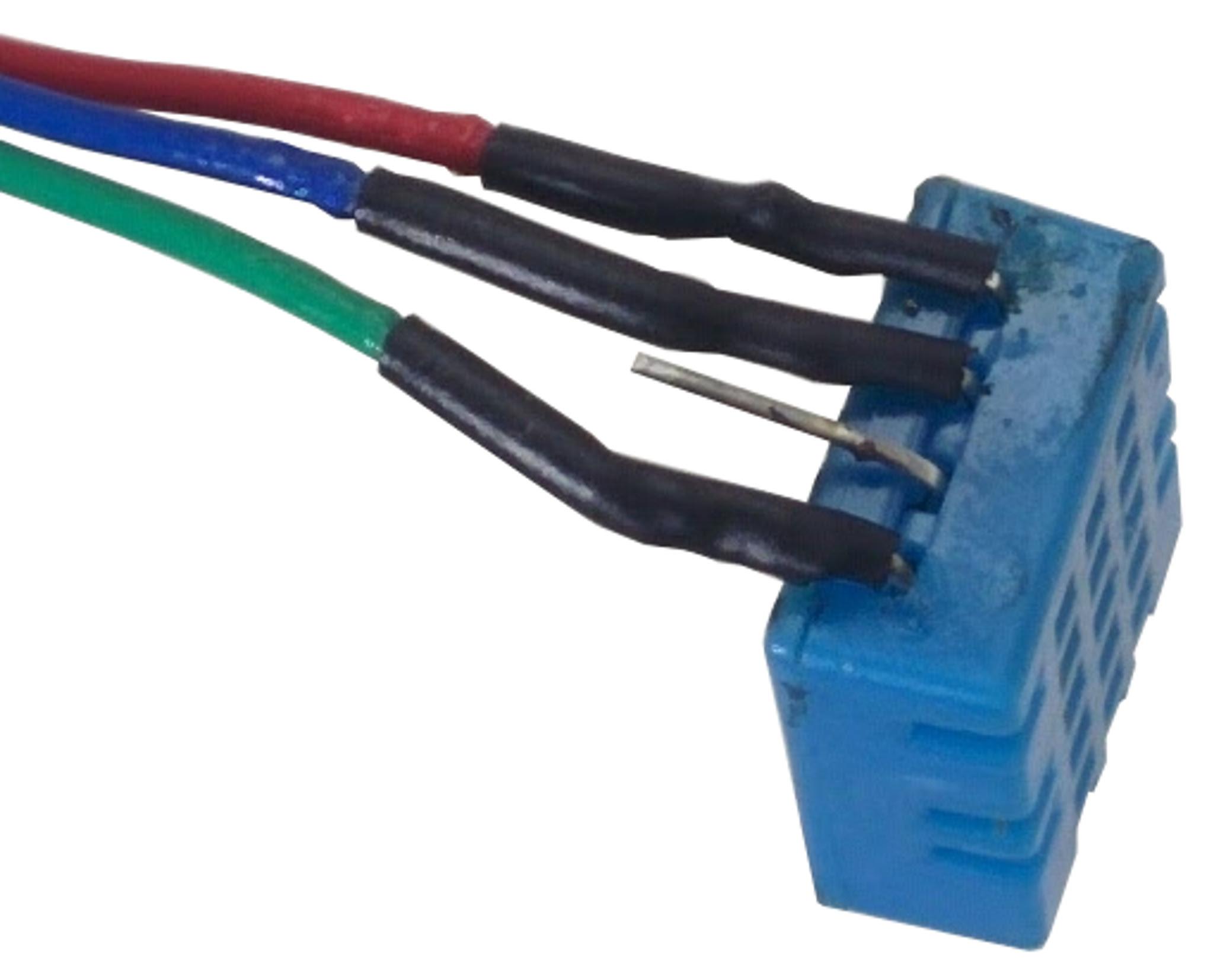

We begin by wiring the sensors that go on the sensor box as shown below with the proximity sensor. Red and Green are always +Vcc and Gnd respectively. The yellow wire is the data line for this sensor. Cut each wire length to about 1.5’. Tin the sensor contacts and stripped wire ends using solder. Solder the wire ends and pins together. Insert the heat shrink tube and shrink this using hot air (eg, a hot air gun, hairdryer etc). Wiring the photocell light sensor.
Wiring the humidity-temperature sensor. Red and Green are always +Vcc and Gnd respectively. The blue wire is the data line for this sensor. After soldering the wires and shrinking the tubes, fold the pins towards the backside gently but firm. Do not unfold the pins after this(or they may break)
The photocell sensor does not have polarity. One end is the data line and the other is goes to Gnd.
Assembling the Sensors
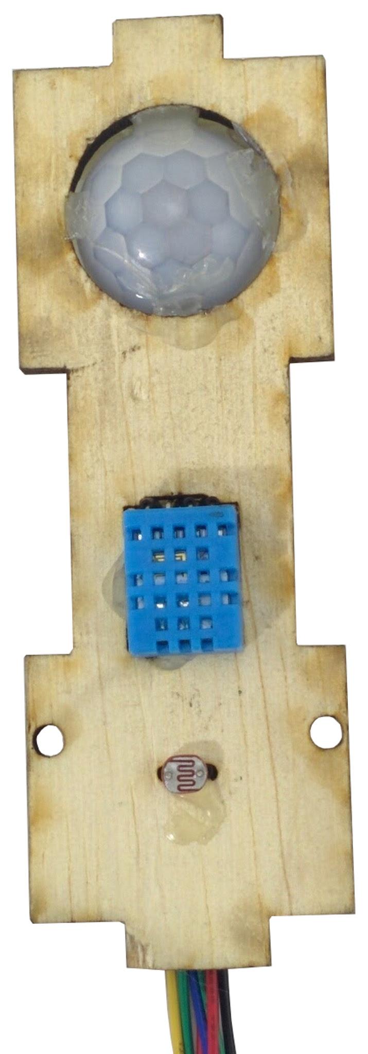
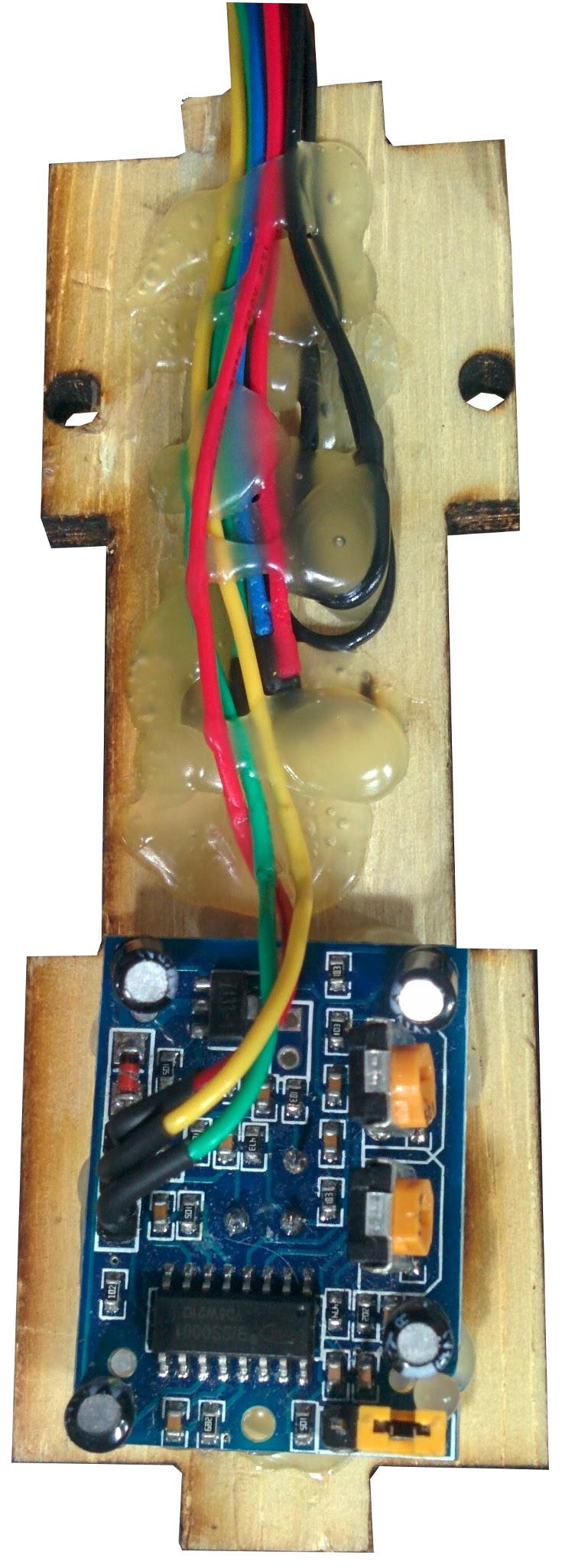
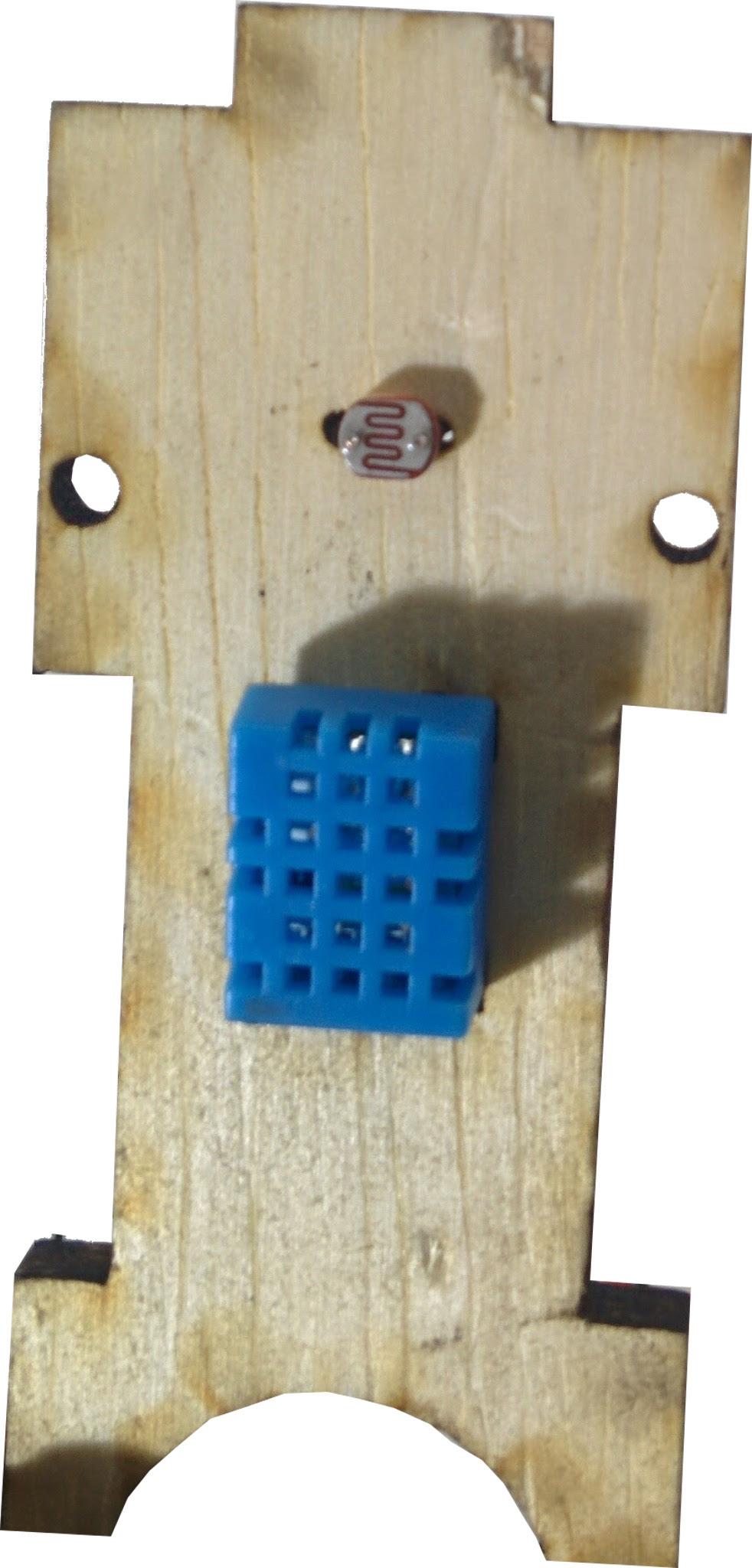
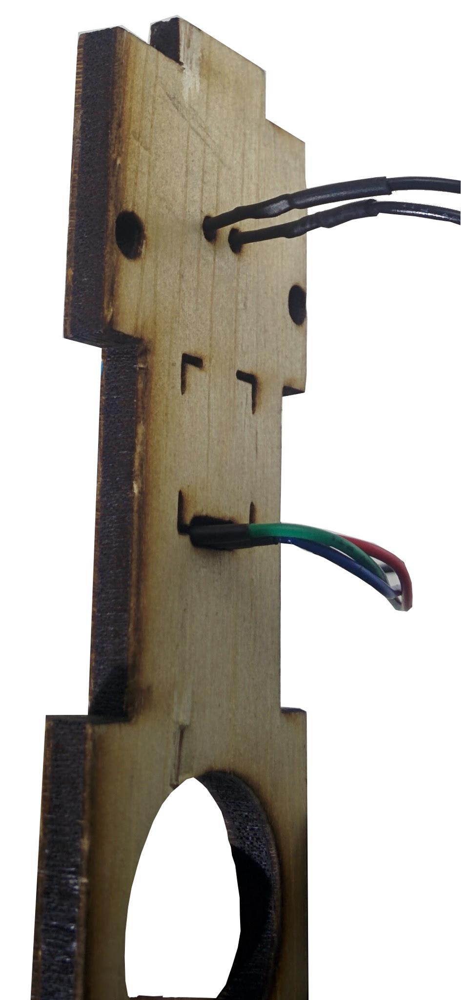
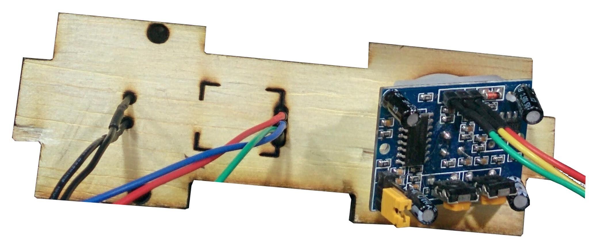
Insert the light sensor and humidity sensor pins through the sensor box as shown.
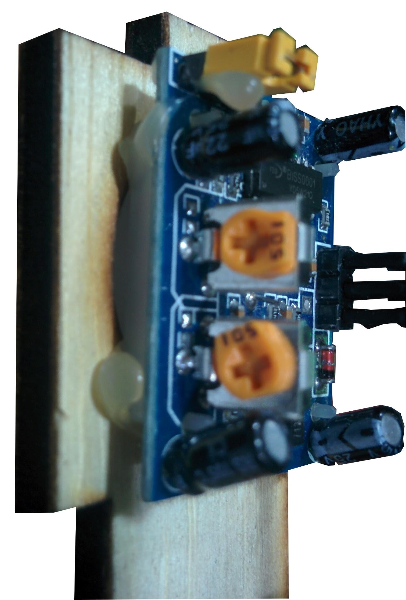
Insert the proximity sensor from the back as shown. Orient in search a way that the side pieces of the sensor box fit. Ie ..with the wire header on the right of left side when the sensor box is held upright. Tack the proximity corners using hot glue. Try not go glue beyond the sensor width so as not to block the side pieces of the sensor box from closing together.
Assembling the Sensor Box
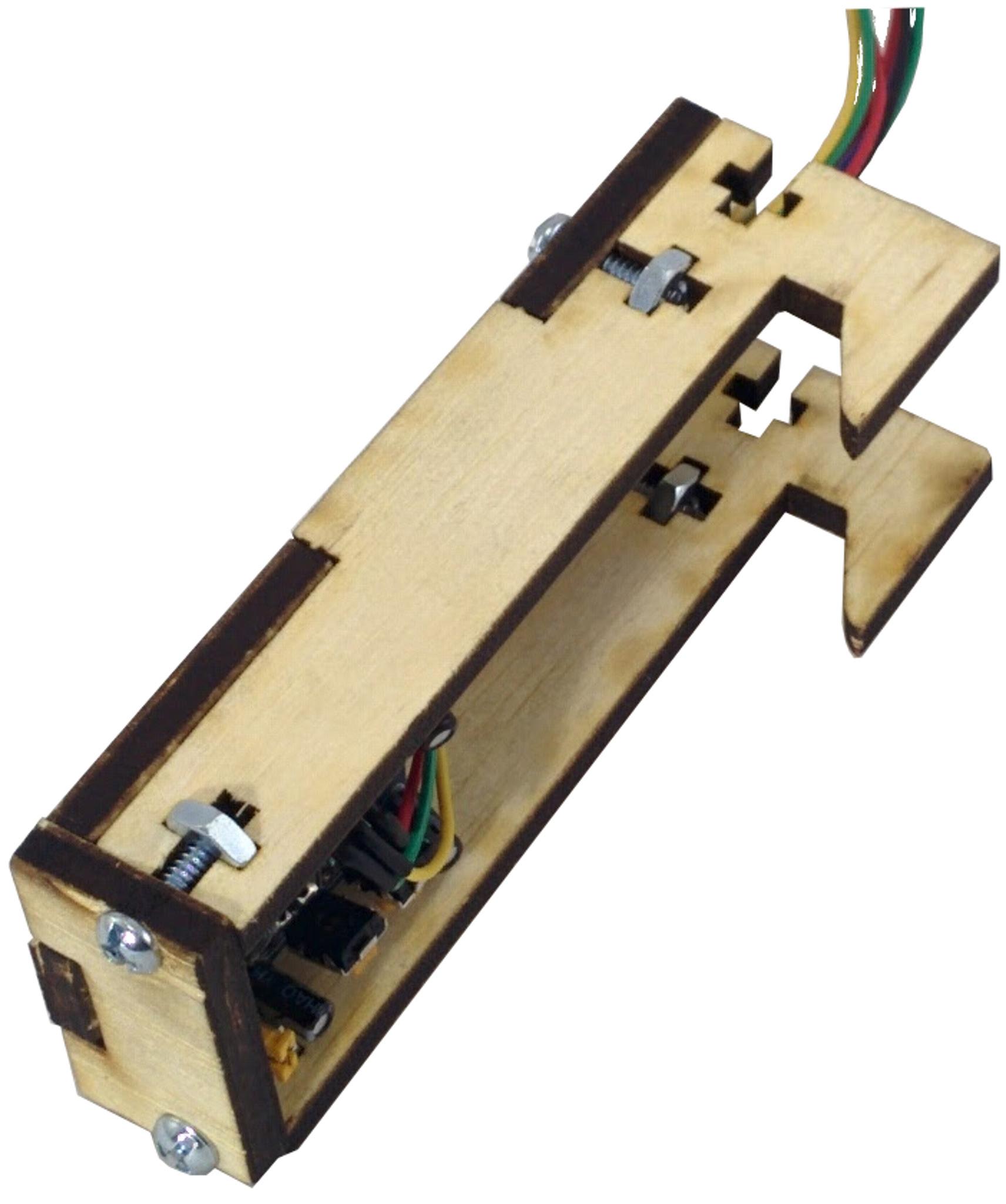
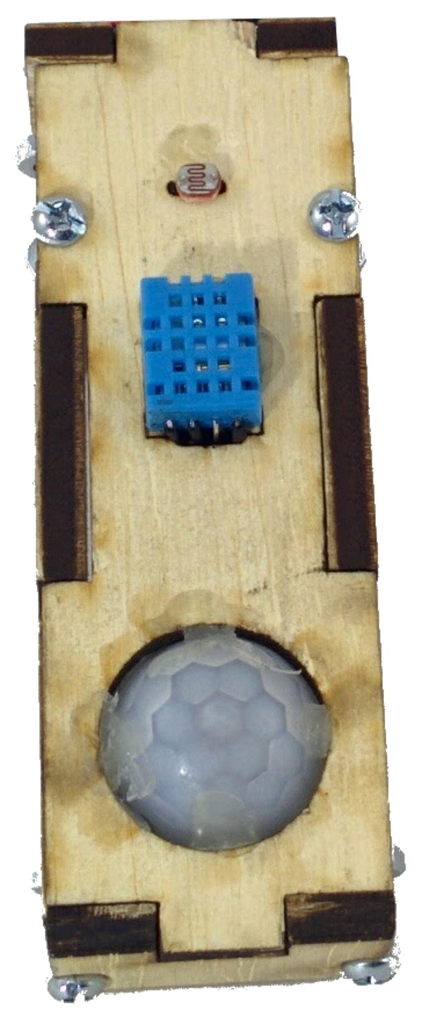
Wiring the Environmental Sensors
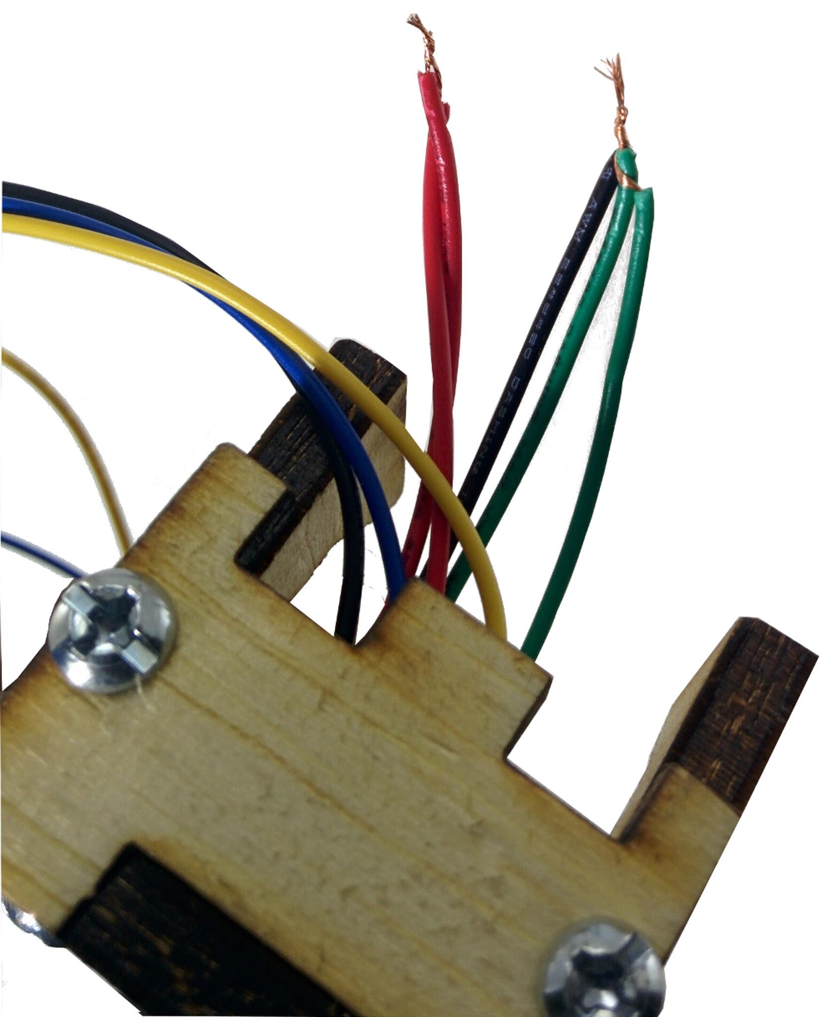
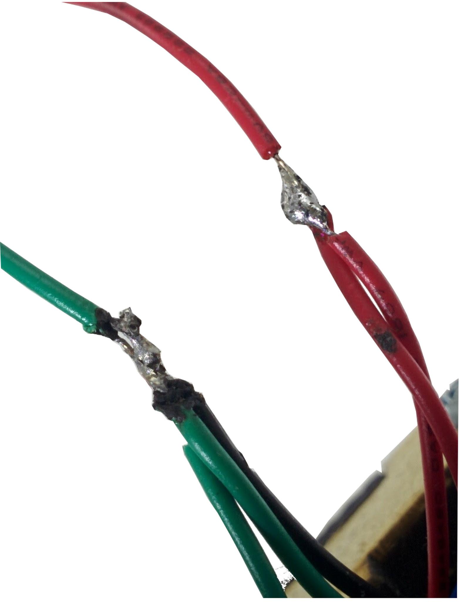
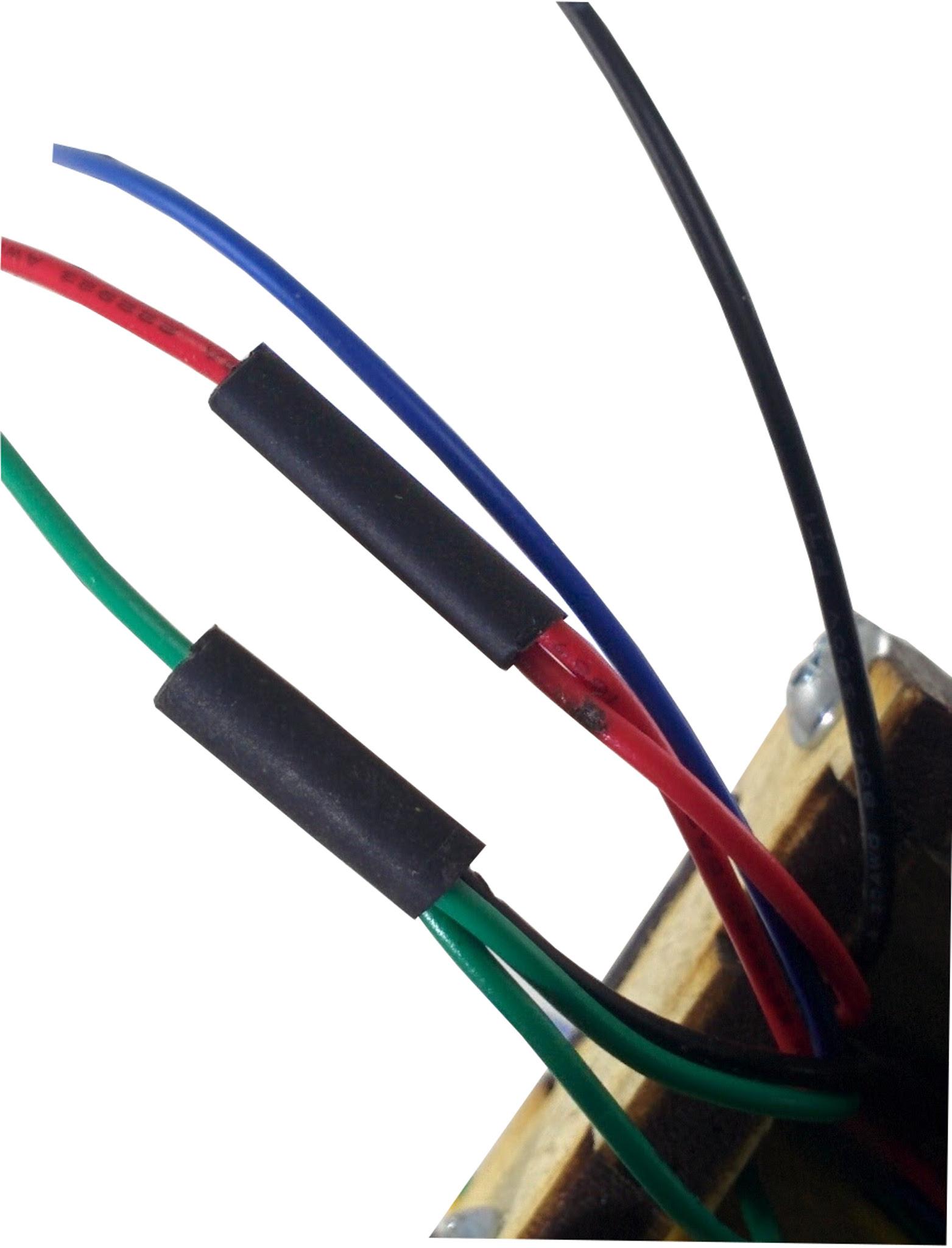
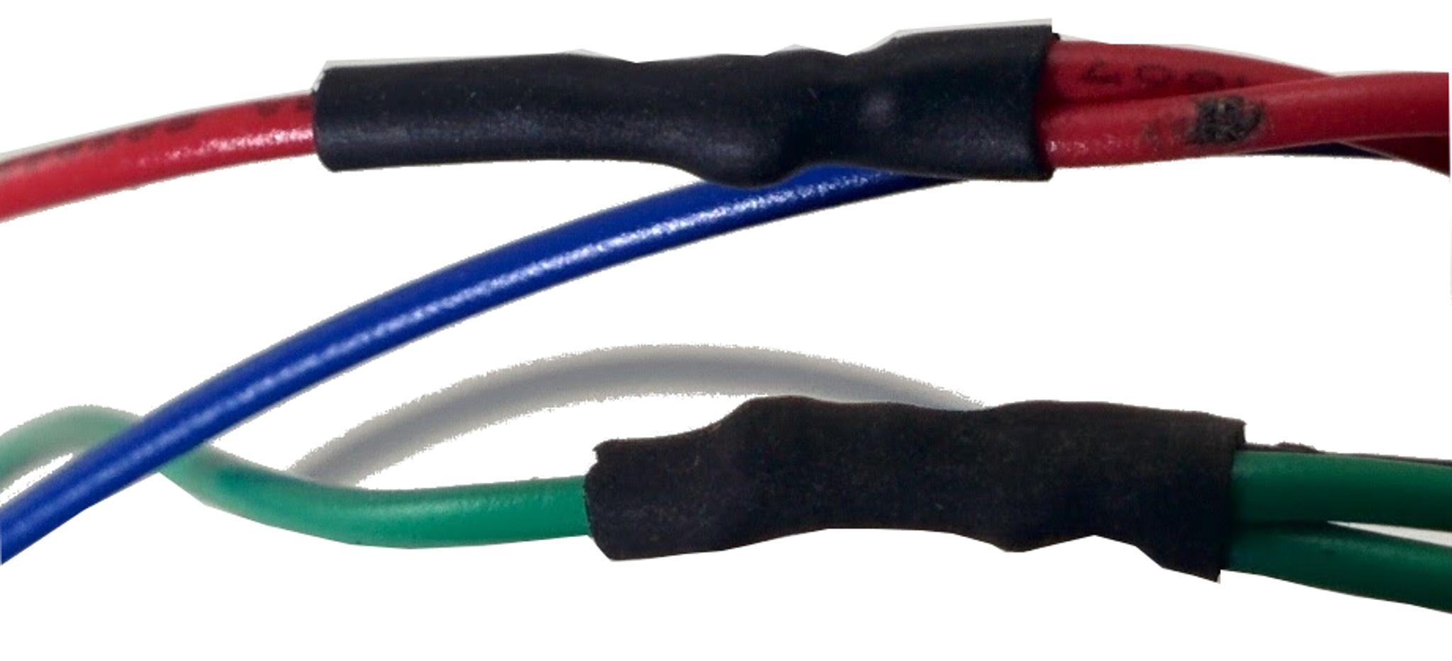
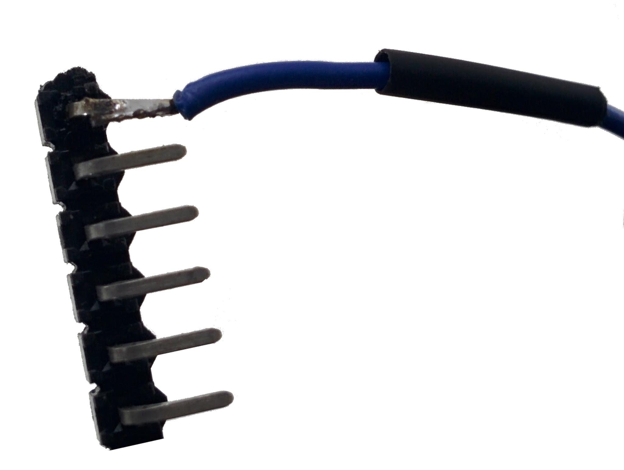
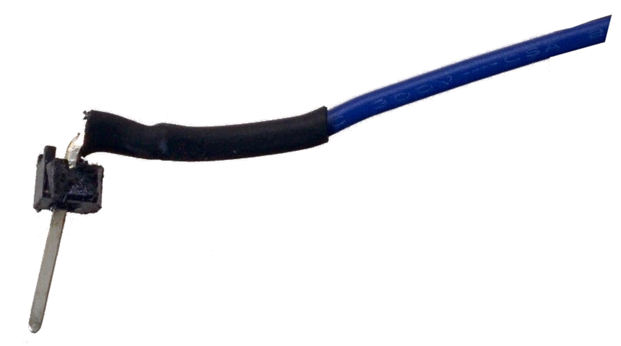
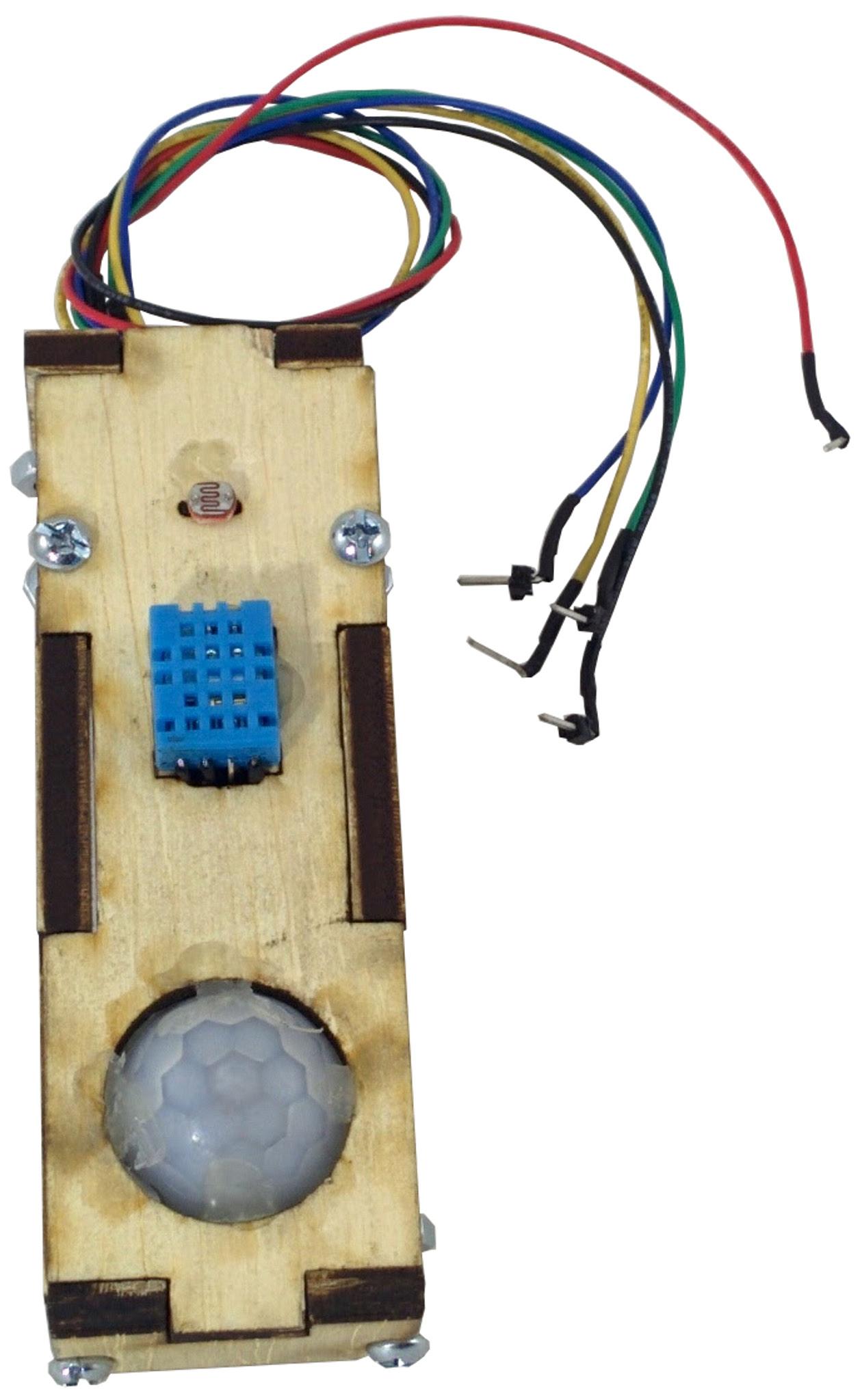
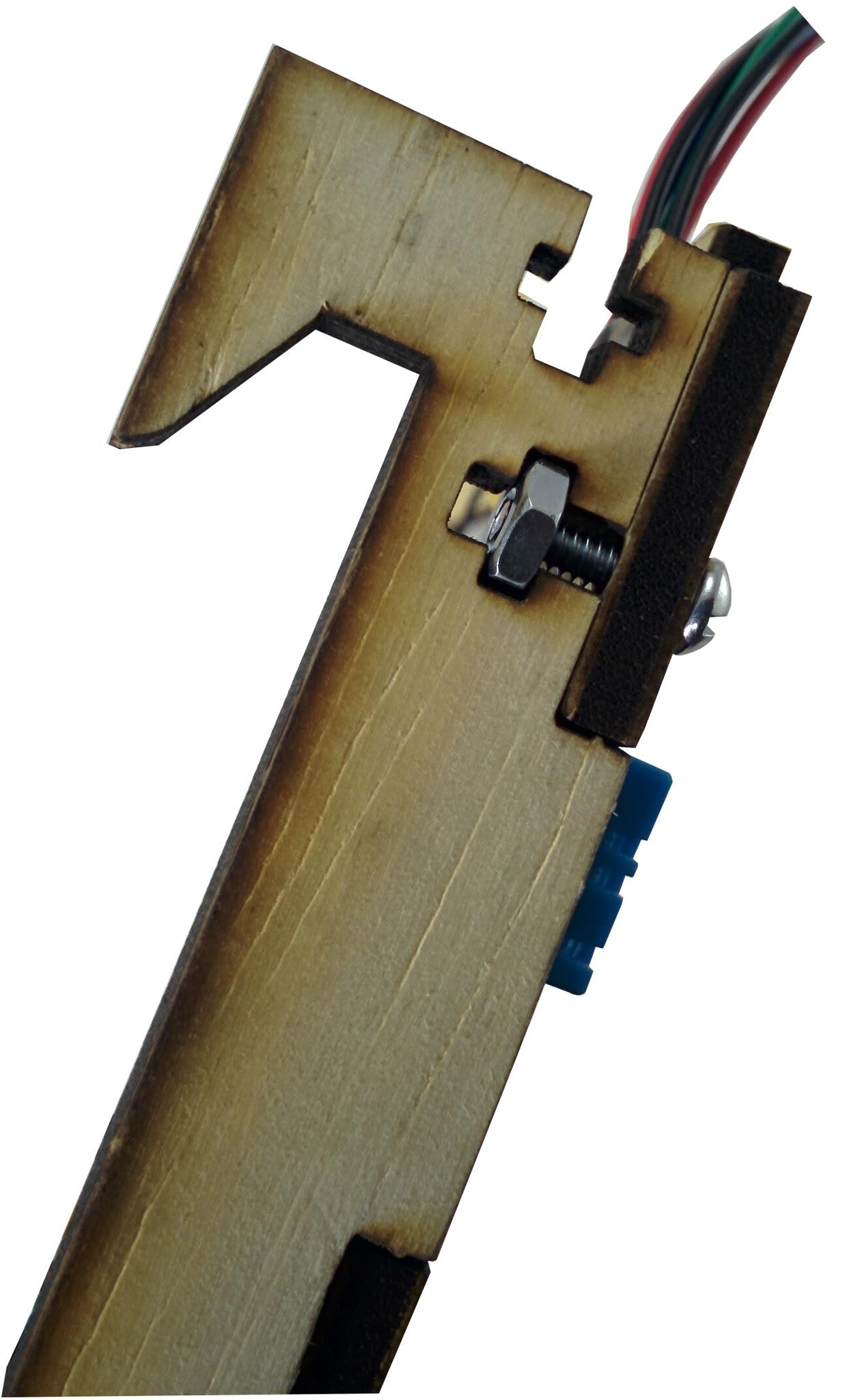
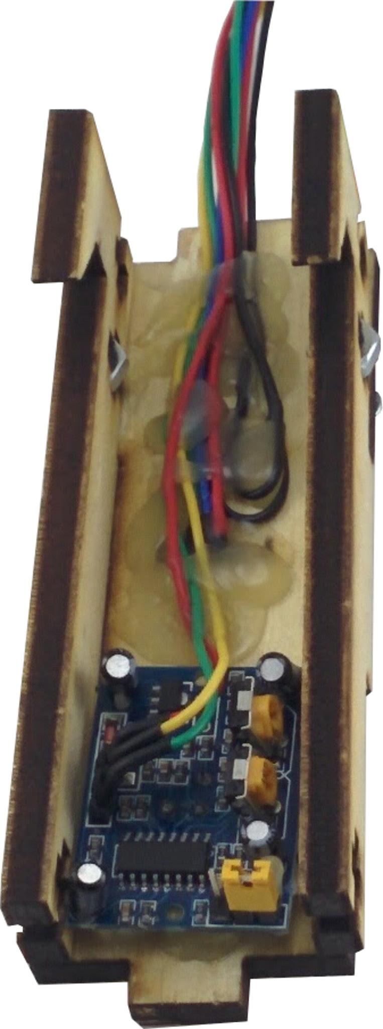
We will now complete the wiring of the sensor box. All the sensors require grounding, where the proximity sensor and the humidity sensor require +Vcc. To simplify wiring we will connect all the sensors to a common power source. We begin by sniping all the ground(green) and +Vcc to a manageable length say 2” long as shown below (do not snip the data lines from each sensor). Strip the power wires and twist the stripped ends together. For the ldr sensor, you can use either wire as ground and the other as data. The ldr is the black wire. Tin the stripped end using a soldering iron and solder, shown. Strip and solder the tips of one of the longer red and green wires that got clipped off from the sensors earlier. Solder and connect the wire with the power wires from the sensor box as shown below (only better, i iron was too hot) Cut out short sections of the heat shrink sleeve, just enough to cover the soldered joints (~1cm) and slip these through the other end of the ground and +Vcc wires as shown. Shrink these using hot air such as from hot air gun or a hair drier to make an electrically and mechanically joint as shown. We address the other ends of the wires from the sensor box by terminating them with pcb header pins as shown below. Insert the heat shrink sleeving before soldering the wire to the pin. After breaking off and shrinking the pcb head, the pin should look as shown below. Repeat for the rest of the sensor data and power wires. The completed sensor box with 3 data and power connections is shown.
Wiring the Tank Water Level and Temperature Sensors
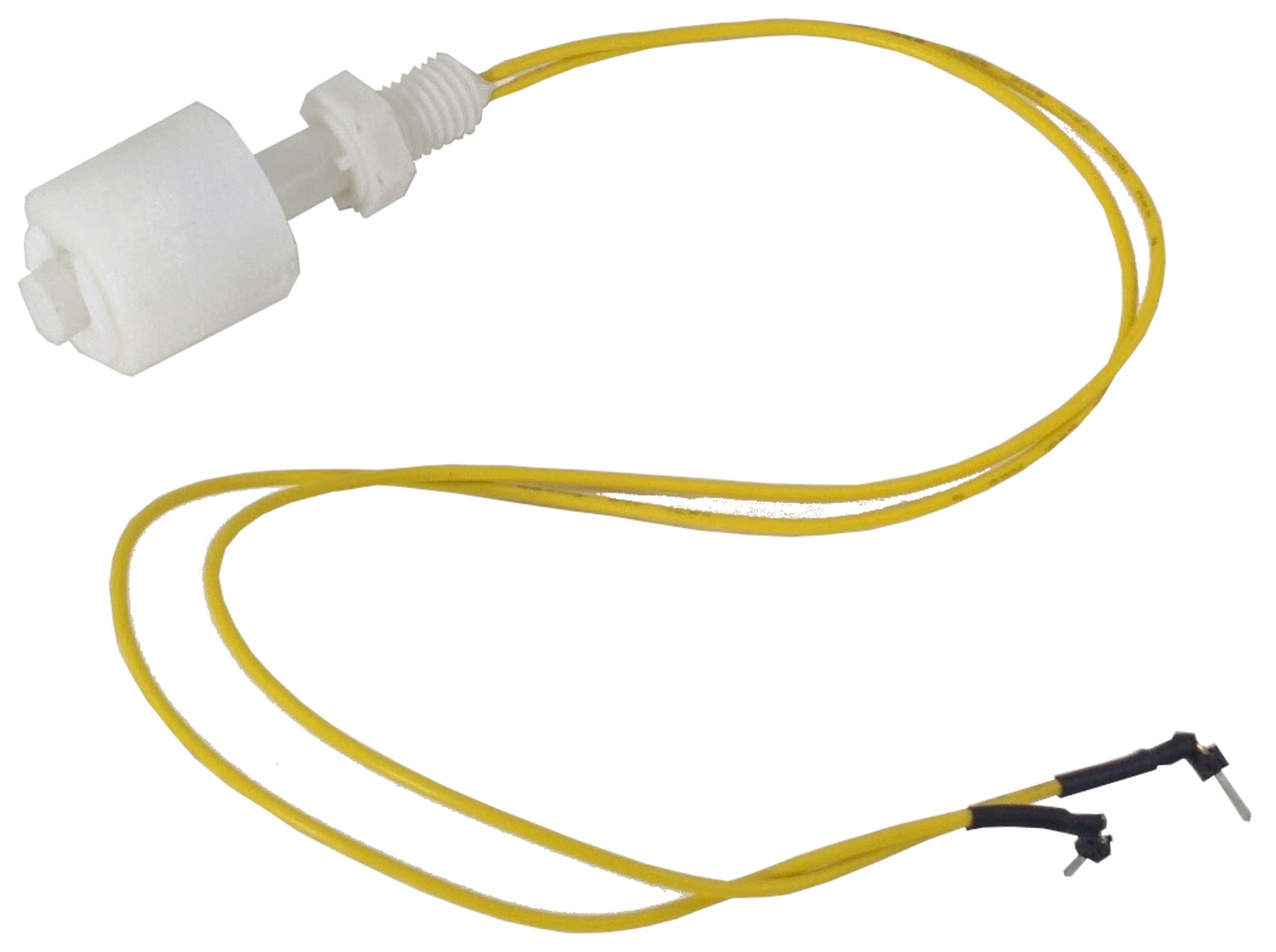
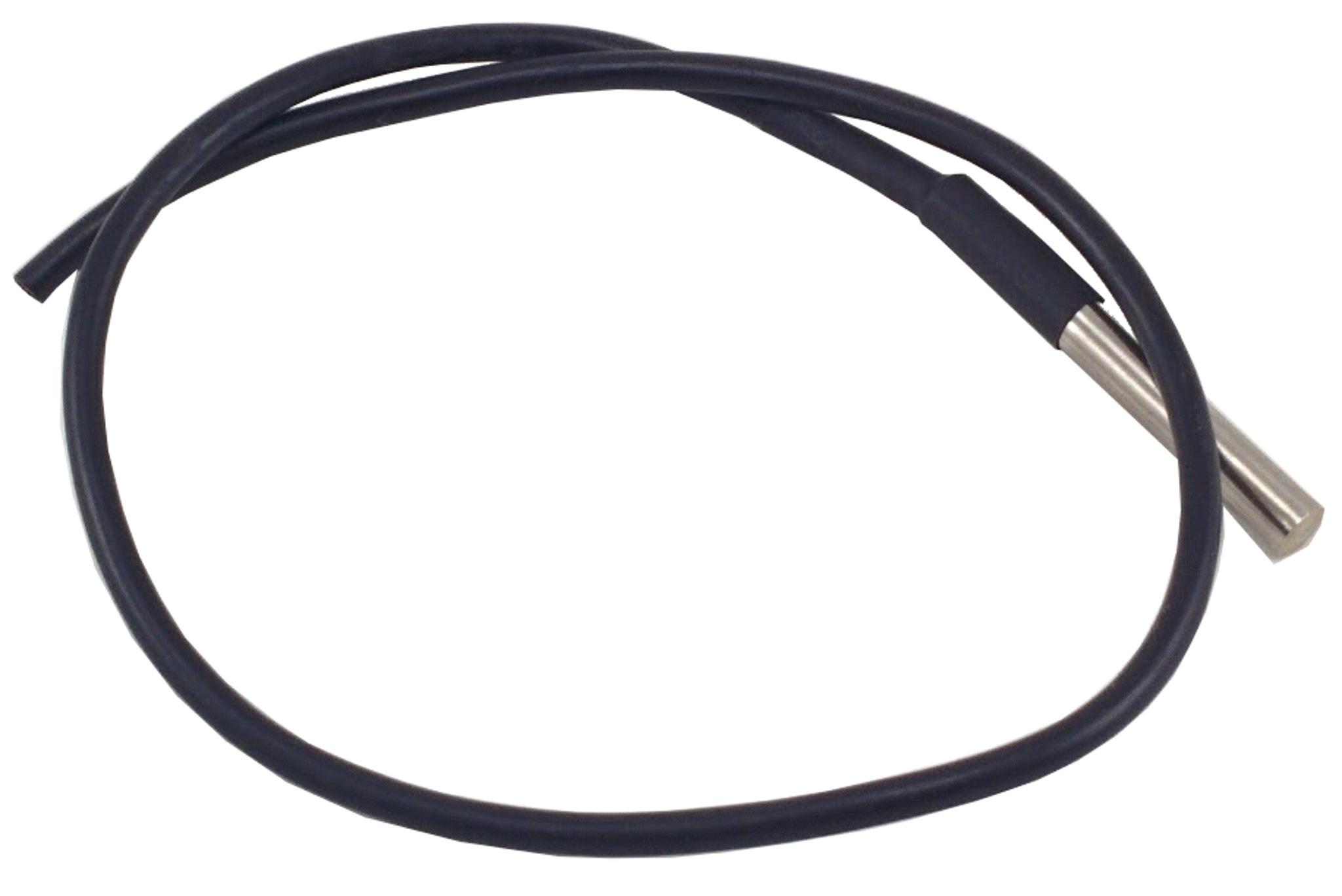
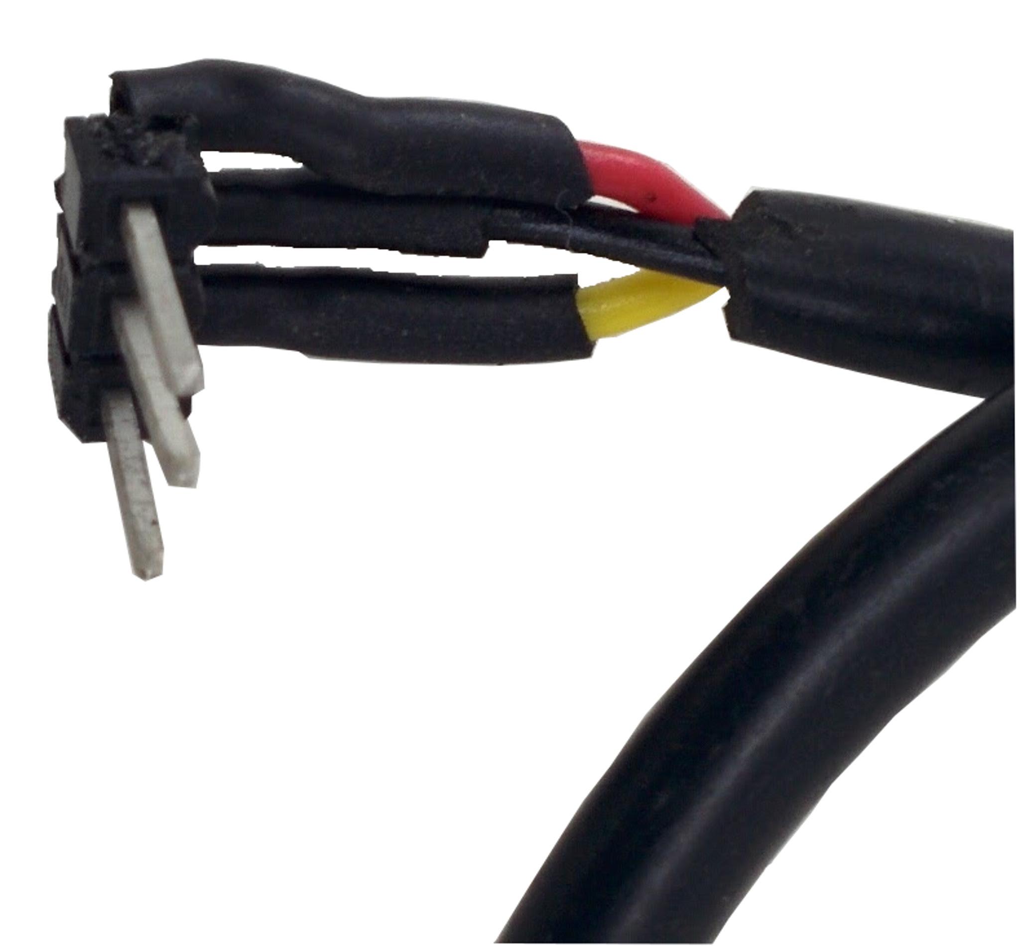
The float sensor is used for the fish tank level and goes inside the fish tank, the wires are normally long enough, we will terminate this with PCB header pins directly as shown. The one-wire temperature sensor measure the water temperature inside the tank. Shorten this to about 1.5” as shown. Terminate this with PCB pin headers and secure with heat shrink tubing as shown.
Paper Circuits - Growbed Level Sensor
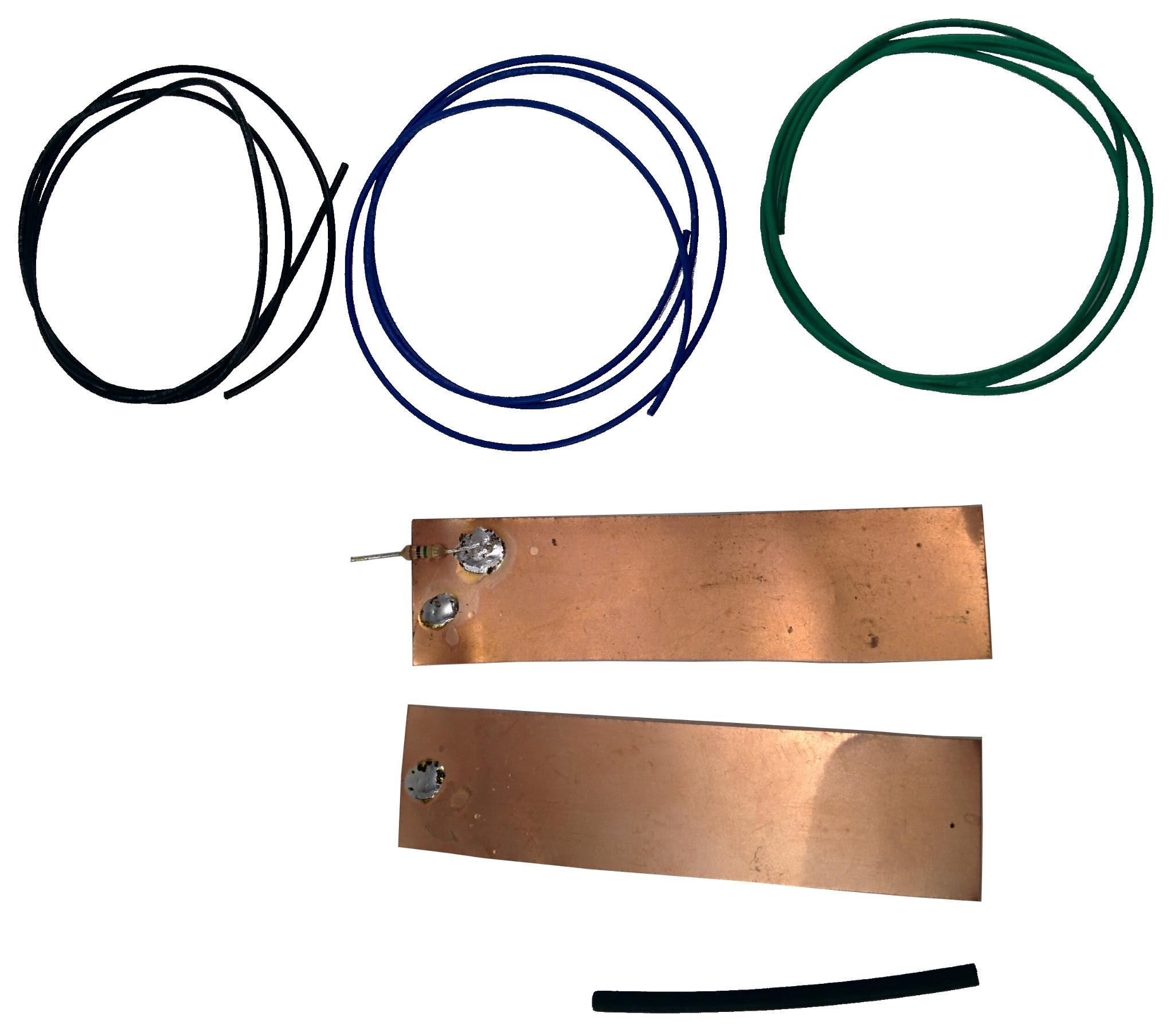
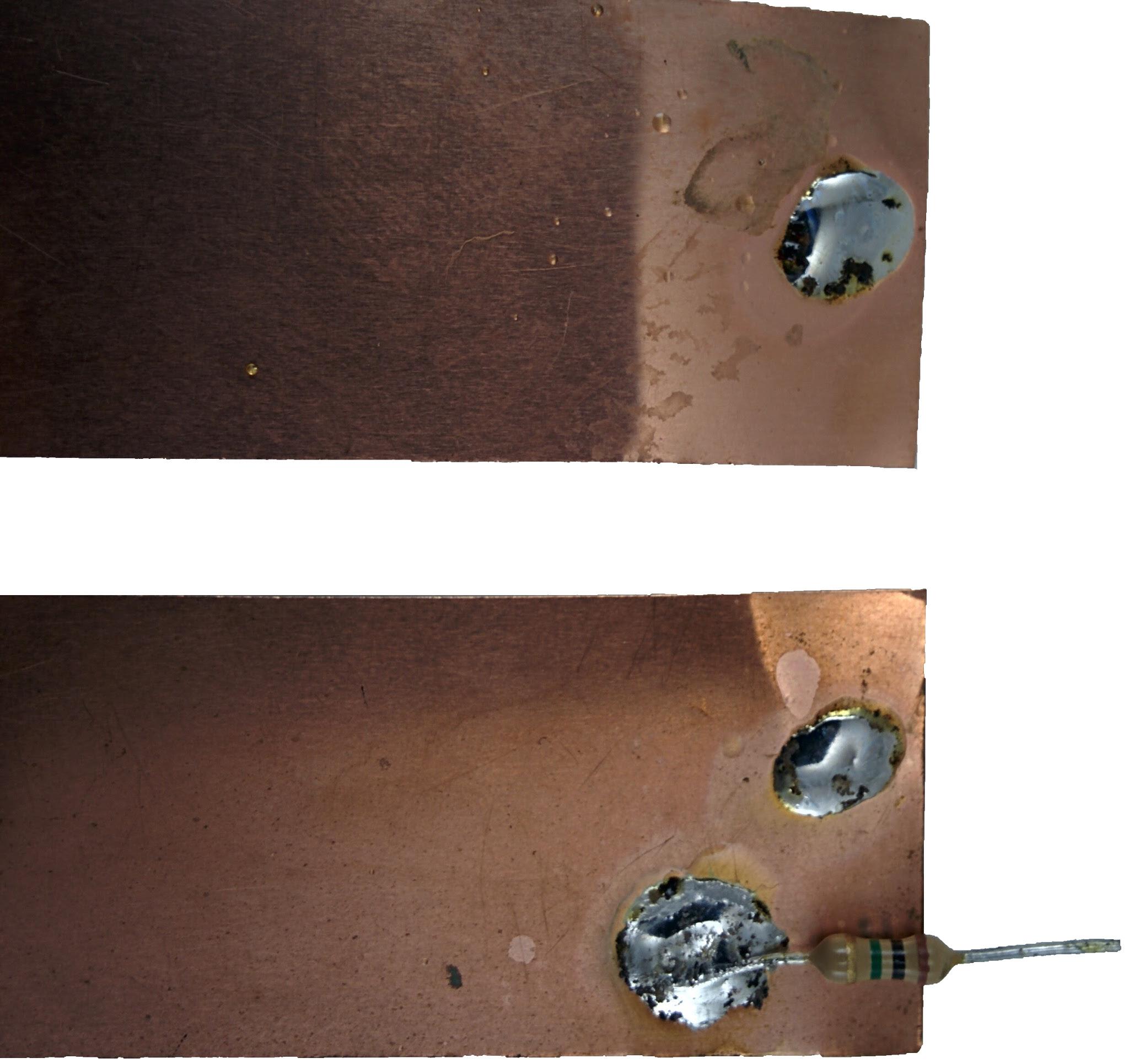
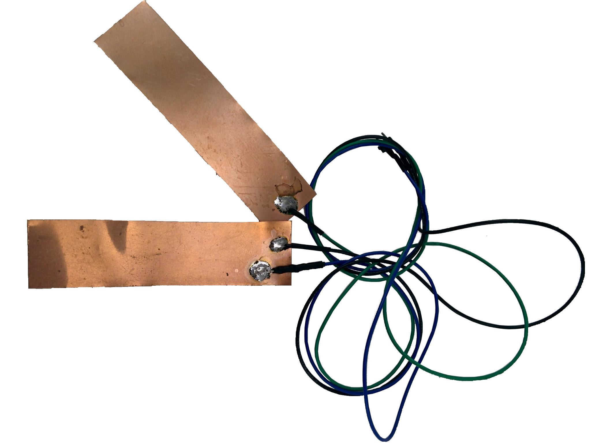
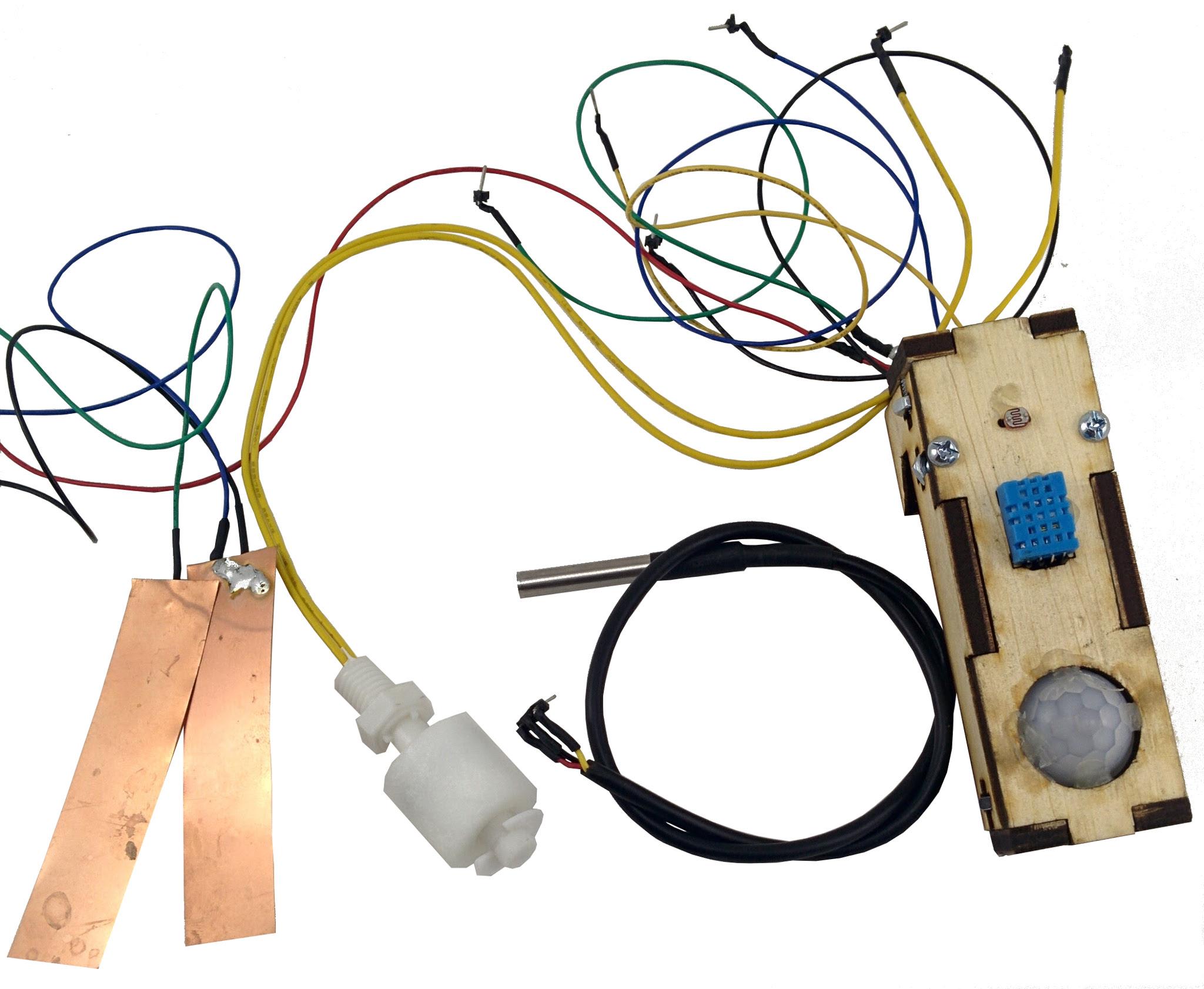
To determine the level of water in the grow bed, a capacitive sensor is used inside the grow bed. We will build this from the copper plates (paper circuits), 1M ohm resistor, heat shrink tubing, and some wires as shown. Begin by soldering the resistor to the copper plate and adding connection points for the wires as shown. You may need to scrape out the waterproofing layer on the plates at the solder points only to make a good connection. Using wires, PCB header pins, and heat shrink tubing to complete the sensor as shown. The second plate connects to the ground (green) while the other two the blue and black are the data sent and receive respectively
Assembling the Tank Sensors Adaptor
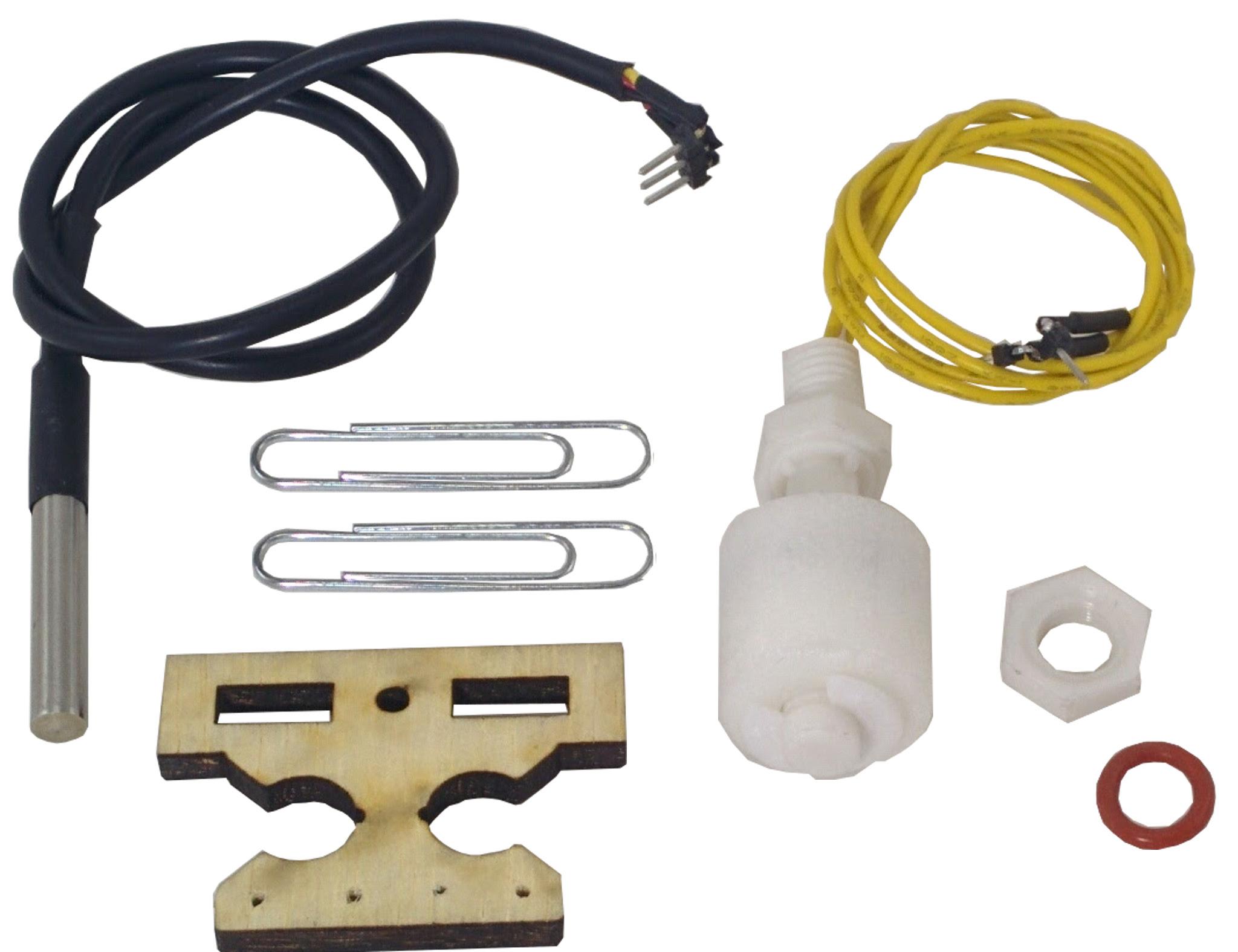
The float sensor and the temperature sensor go inside the fish tank. We will now build the sensor fixture. These are mounted underneath the grow bed using paper clips and a t-slot adapter, shown.
Paper Clip Art - Tank Sensor Adapter

Begin by straightening out the paper clips. Mark one of the paper clips as shown below using a felt pen or sharpie at 1 cm, 2 cm, 6 cm, and 10 cm from one end
Tank Level Paper Clip Holder
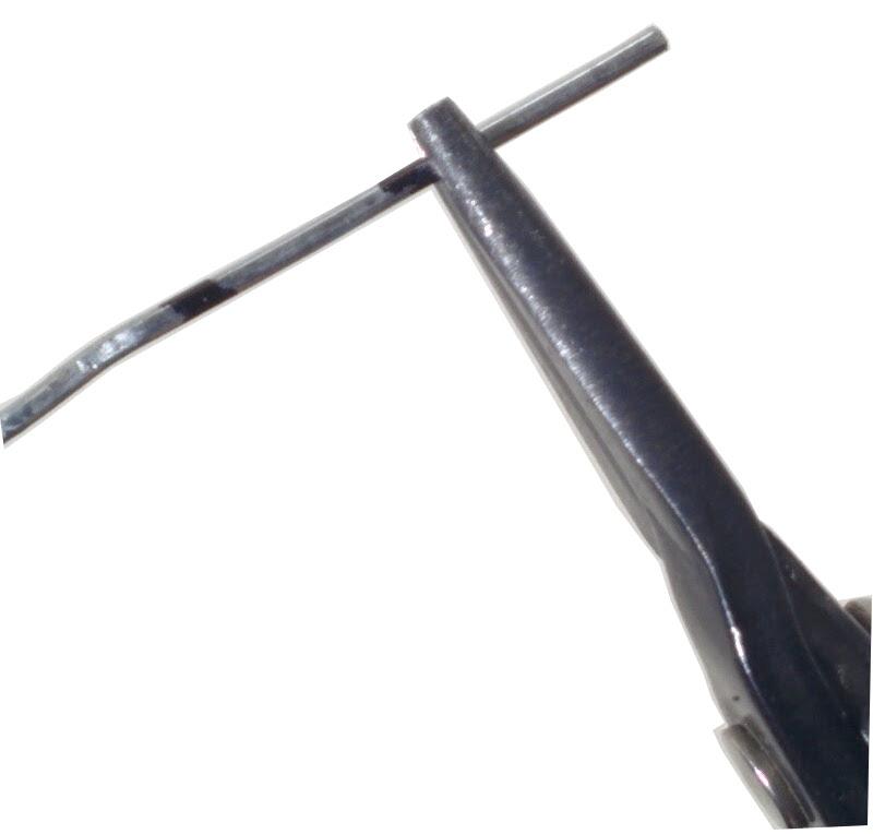
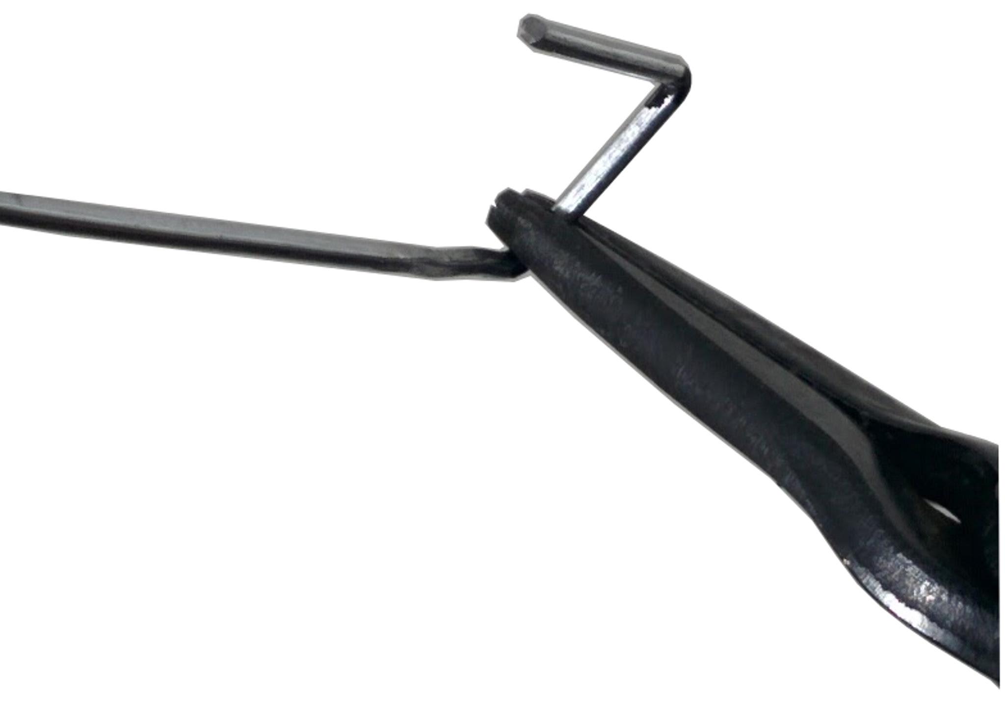
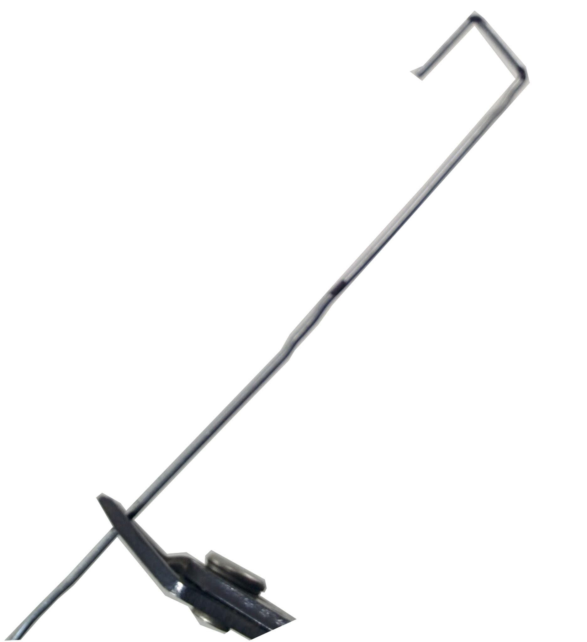
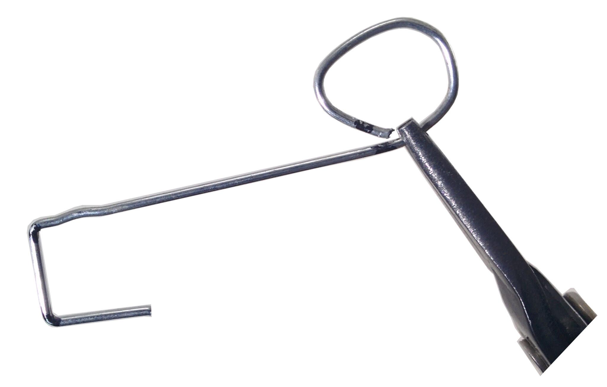
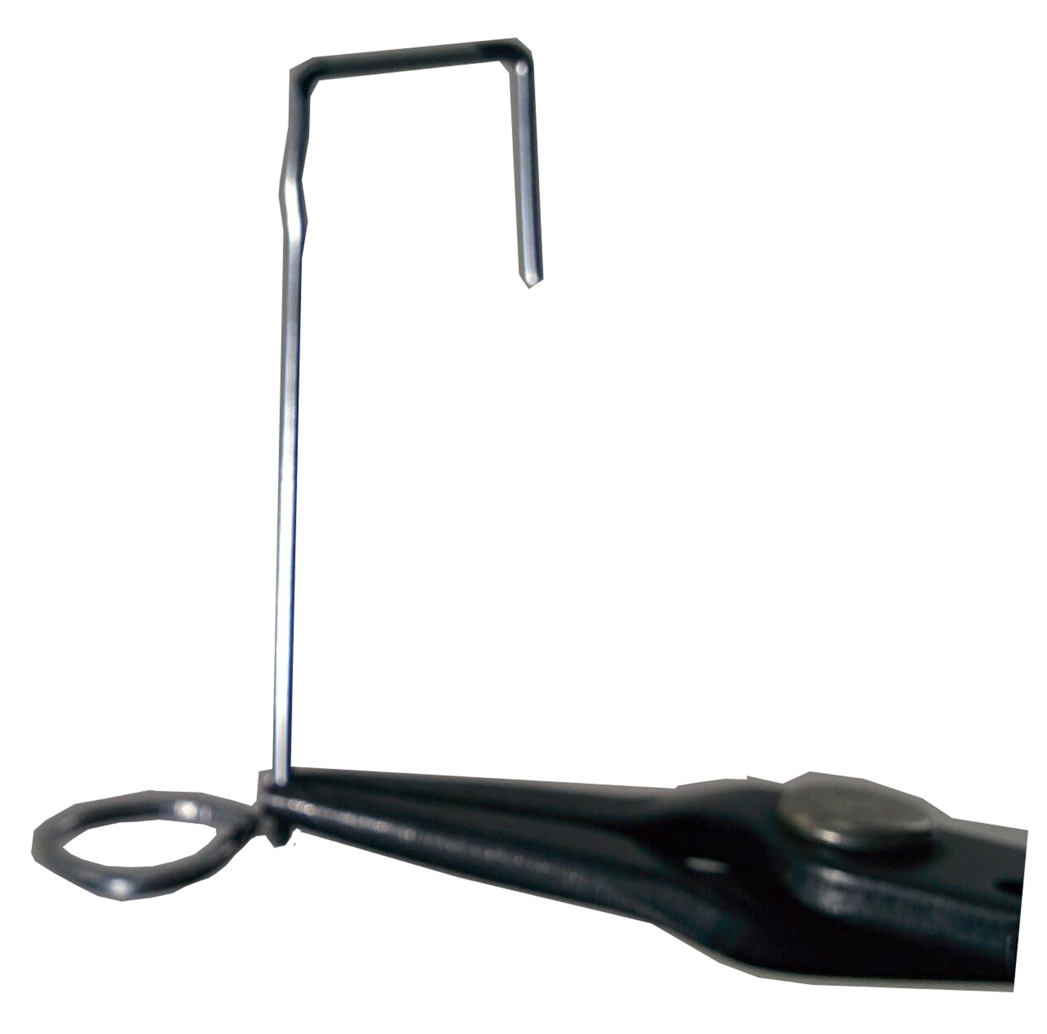
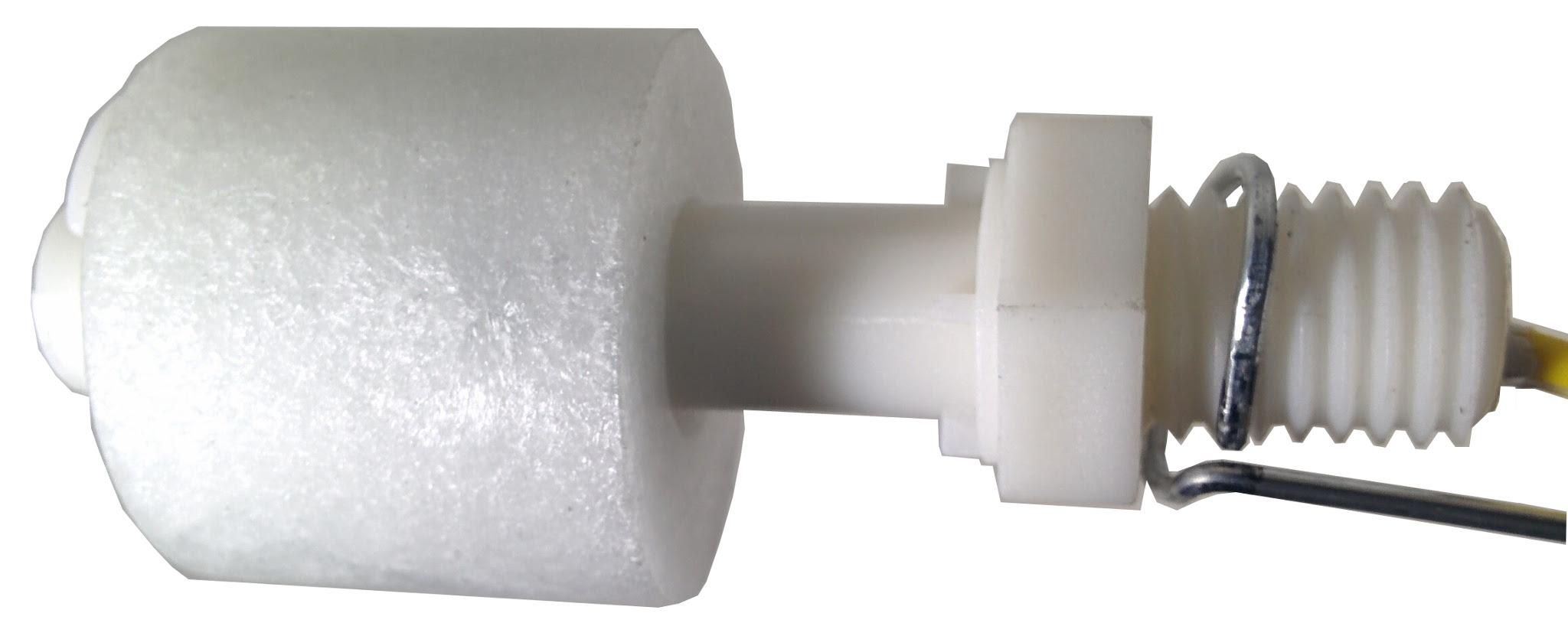
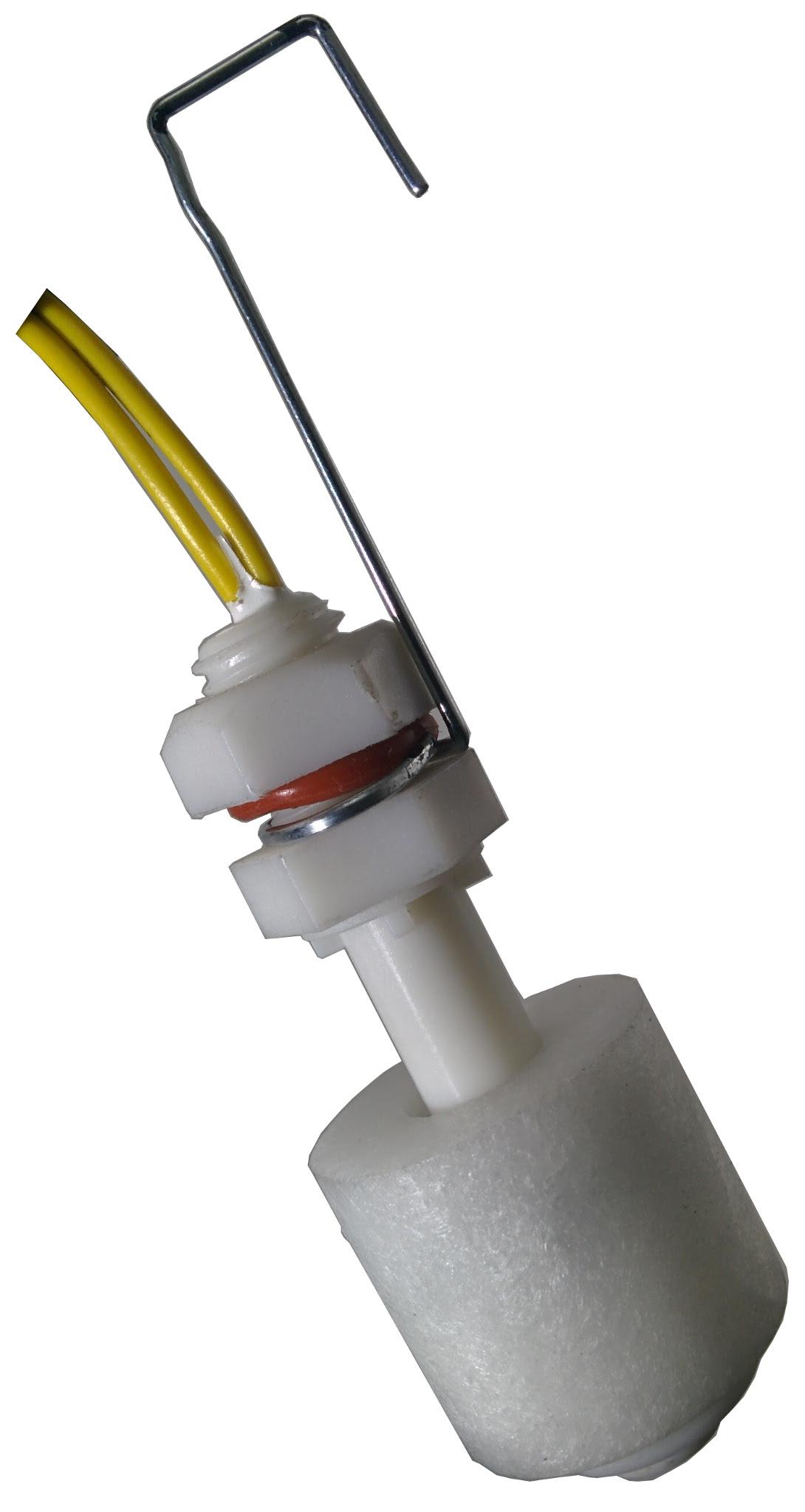
Fold the wire to create right angles at the 1 cm and 2 cm markings as shown. At the 10 cm mark, snip or break the line by holding with pliers and folding repeatedly. Make a circle from the 10 cm end with a circumference to the 6 cm marking as shown. Fold the loop, so it is perpendicular to the steam, as shown. Run the wires from the float sensor followed by the float sensor stem into the loop we just created as shown. Lock the sensor using the o-ring(for storage if available) and the nut as shown.
Water Temperature Paper Clip Holder

Using your sharpie or felt pen, measure and mark out the second wire at 1 cm, 2 cm, 5.5 cm, 8.5 cm and 12.5 cm as shown
Preparing the Paper Clip Temperature Holder
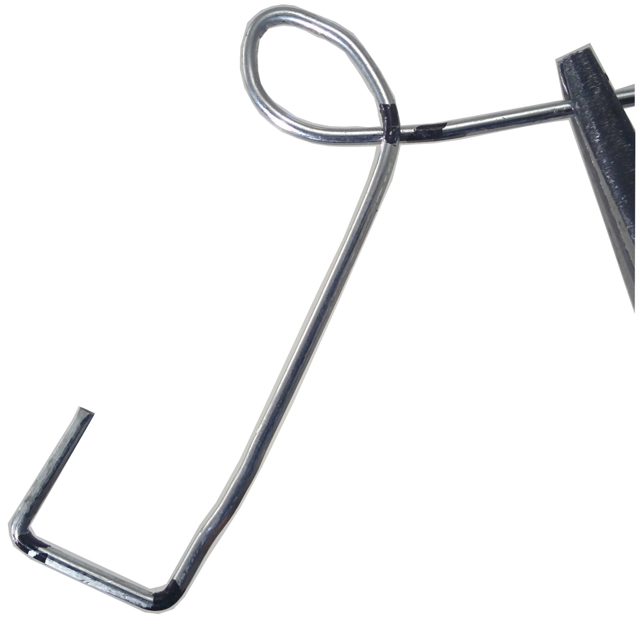
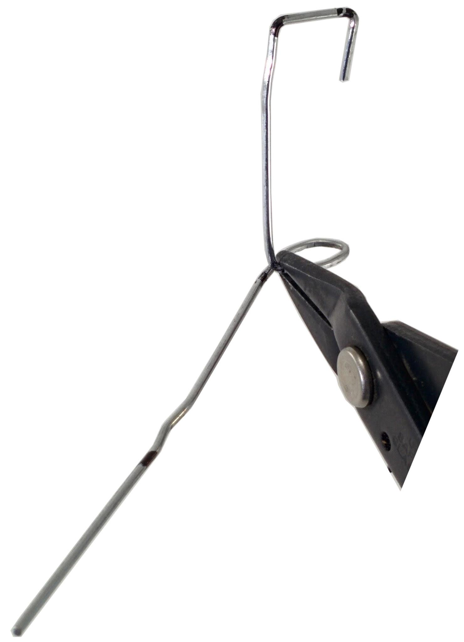
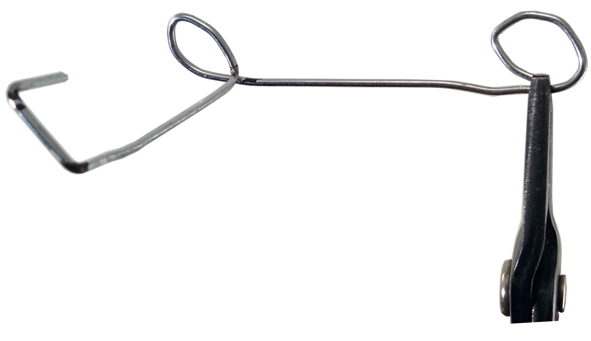
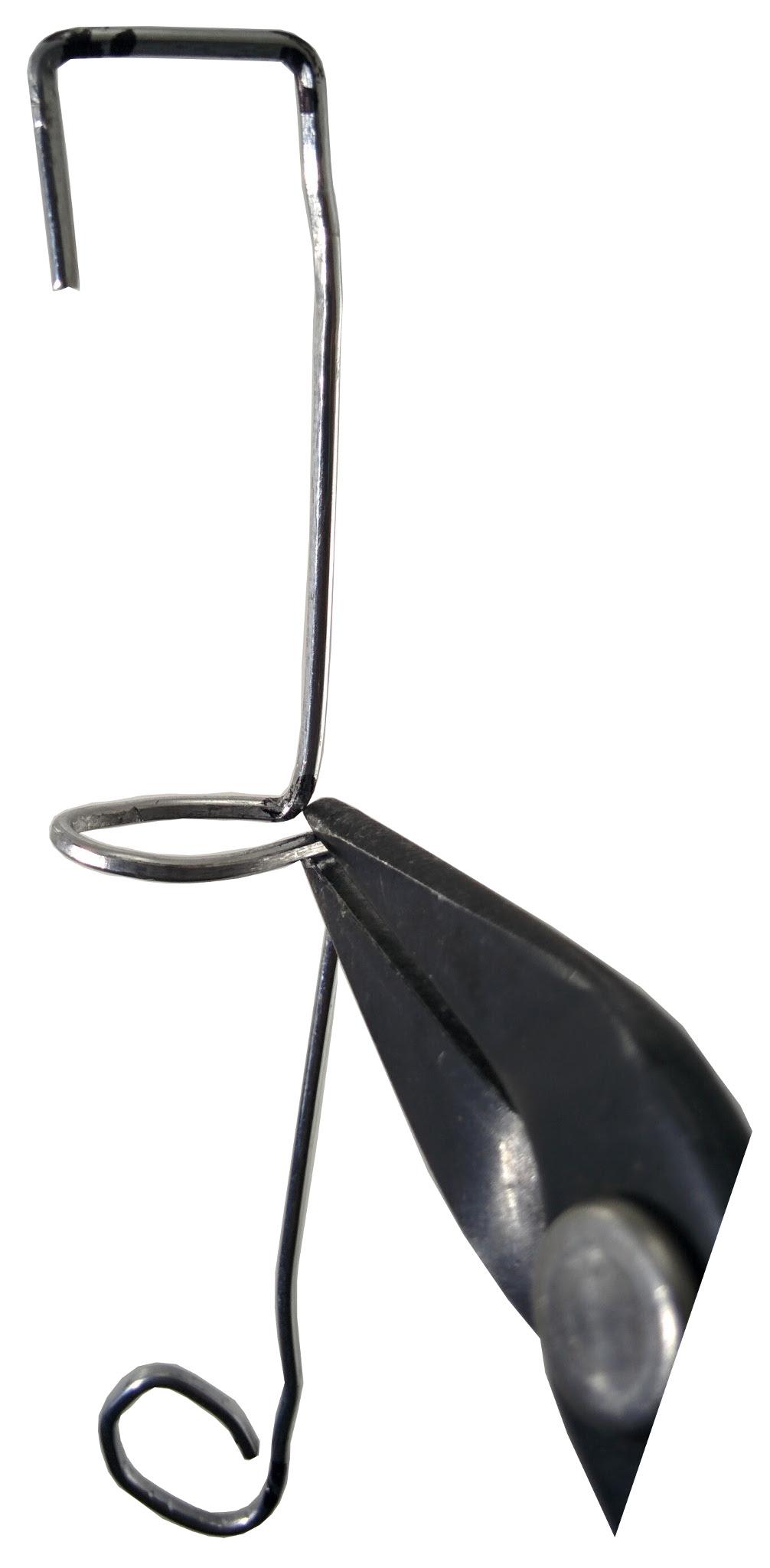
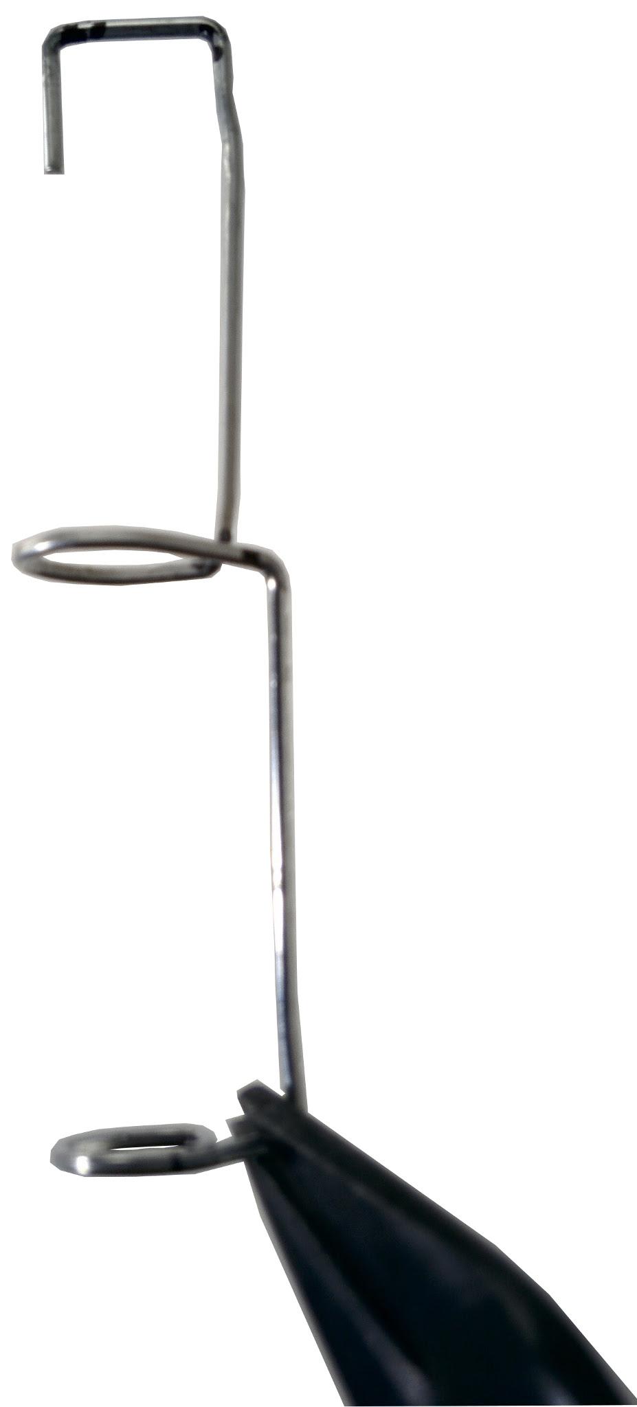
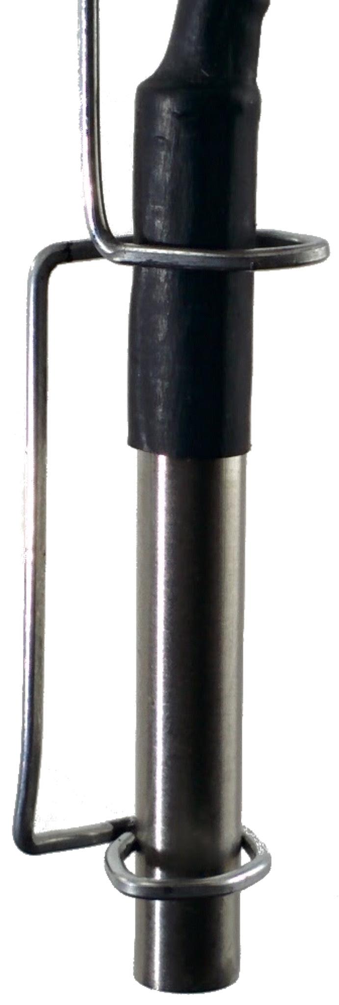
Bend the loop so that it is perpendicular to the right angle folds as shown. Create another loop from the tip of the clip to the 8.5 cm mark as shown. Bend the first loop, so the bottom end is parallel to the right-angled folds. Bend the lower loop until it is parallel to the upper loop, as shown. The wire clip is shown with the temperature sensor inserted
Assembling the Tank Sensor Adapter
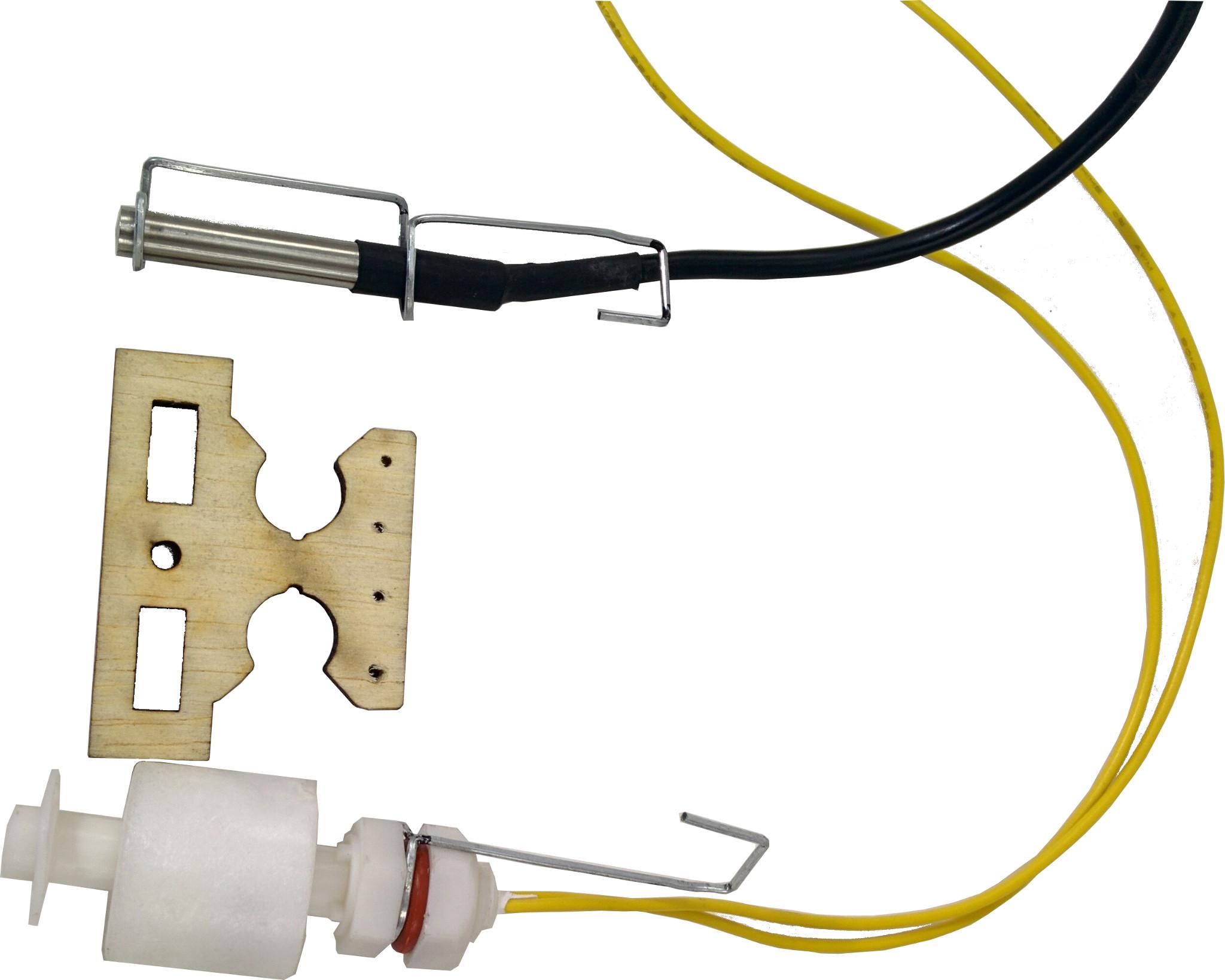
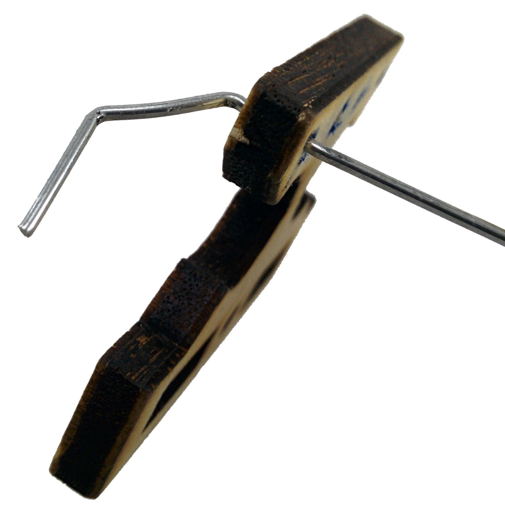
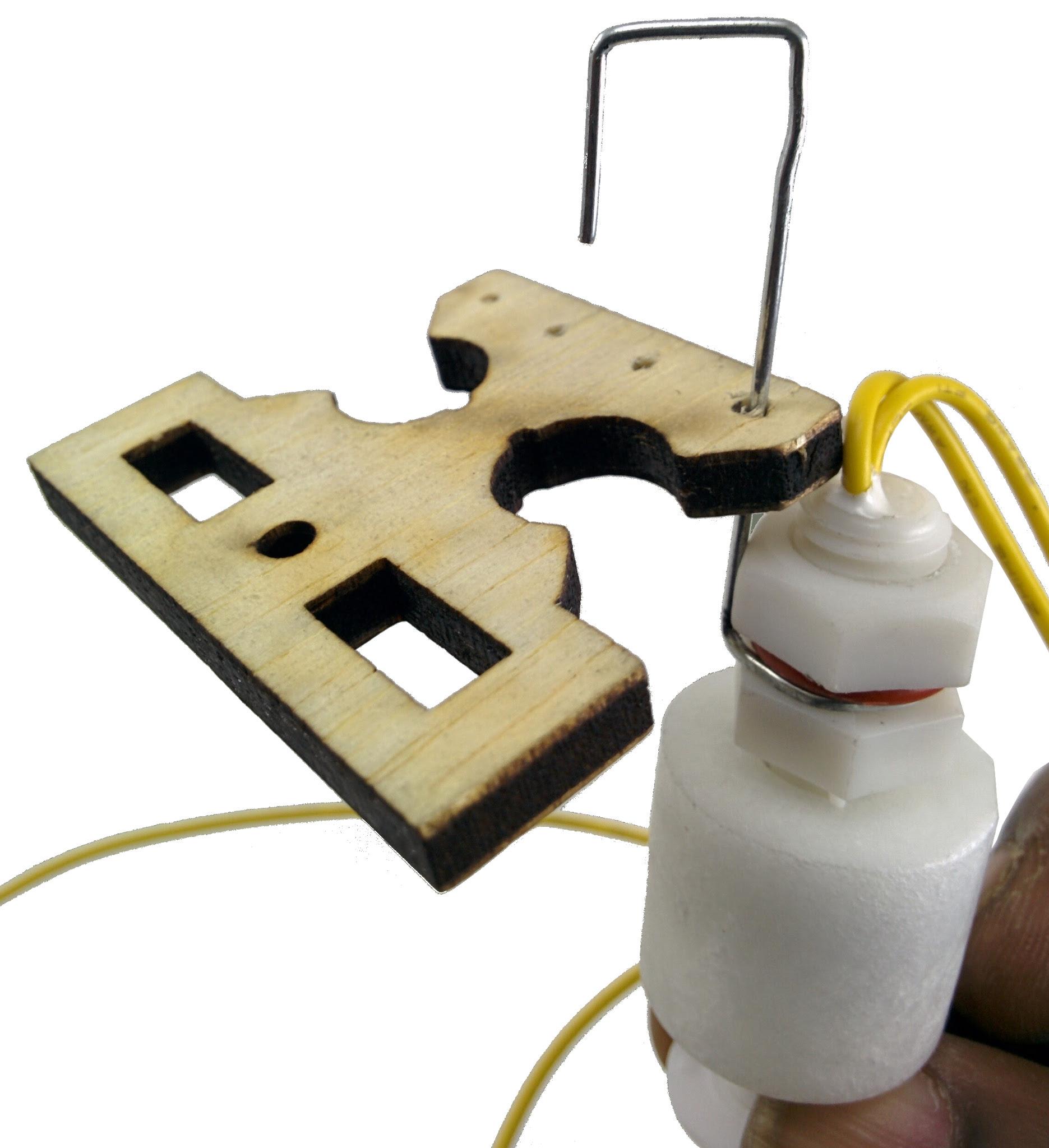
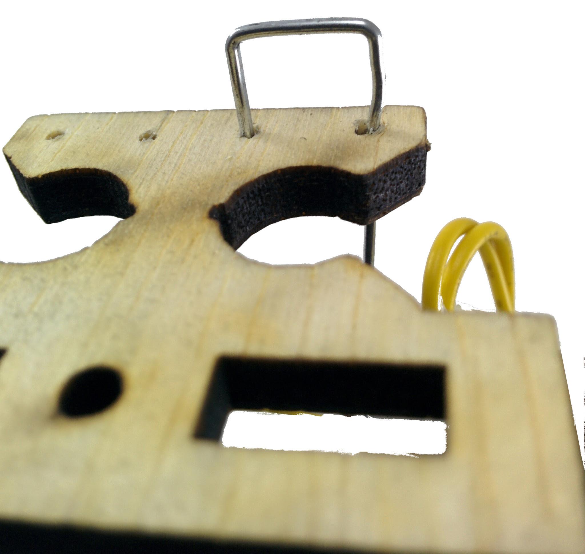
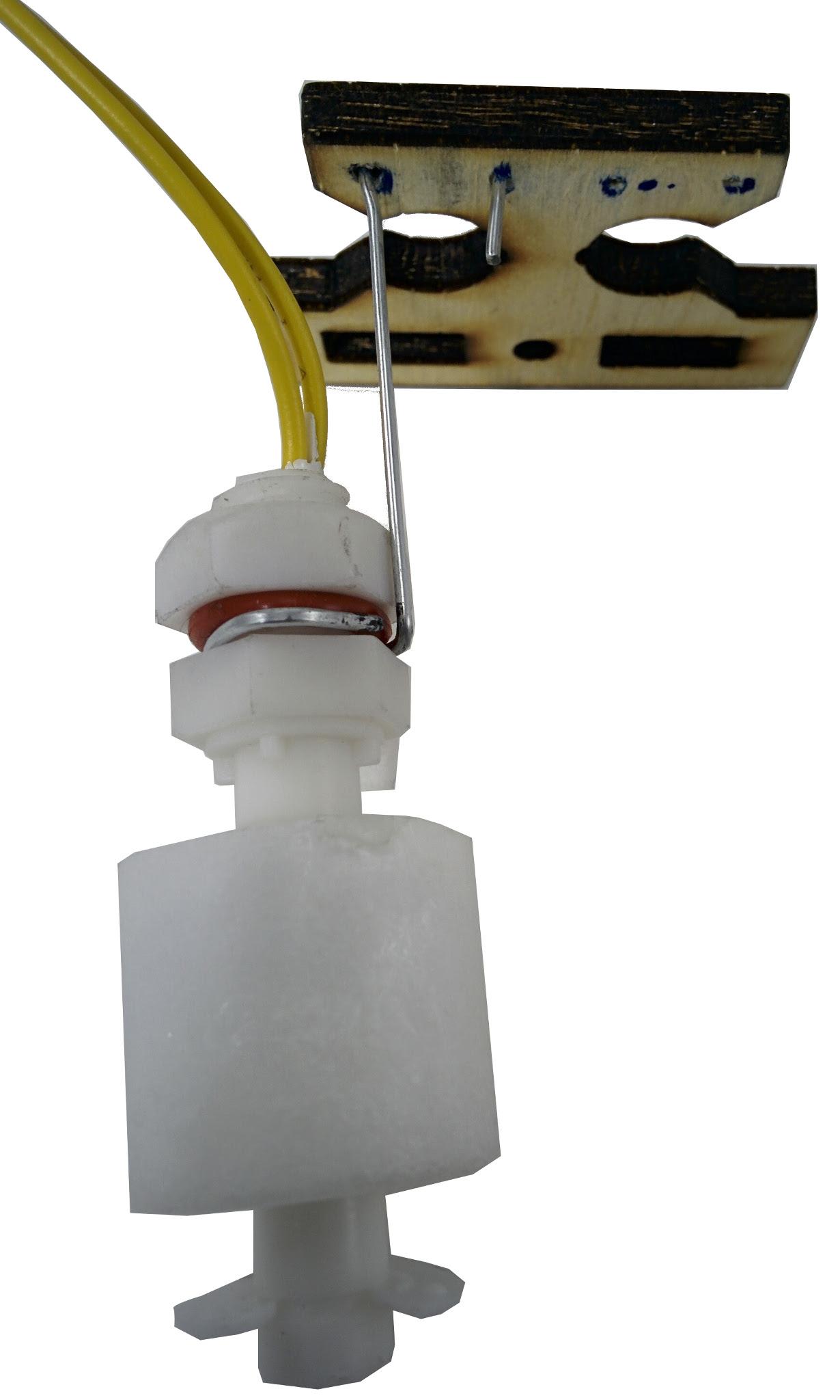
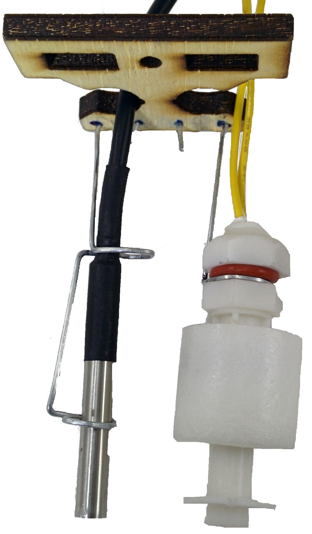
The clipped sensors and mounting adaptor are shown. Straight out some wire on the float switch end and insert it into the mounting adaptor as shown. Re-bend the right angle corners on the wires as show. Insert the wire into the next hole as shown. The float sensor should look as shown from the under once fully inserted. Next insert the temperature sensor the same way into the next two holes on the adaptor as shown. The tank sensor accessory should appear as shown.
Mounting the Tank Sensor Adapter
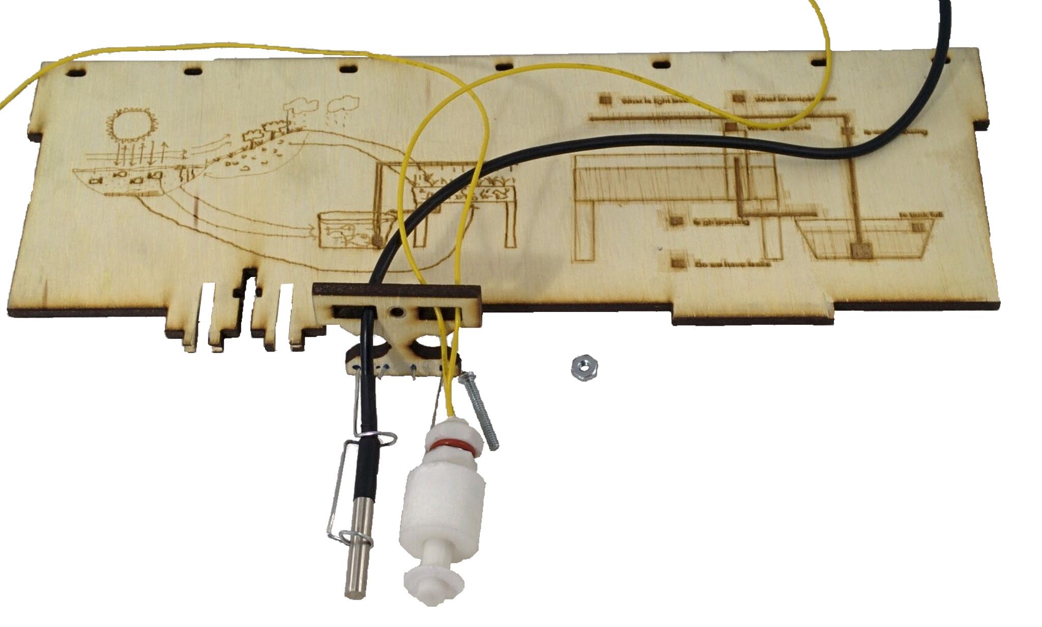
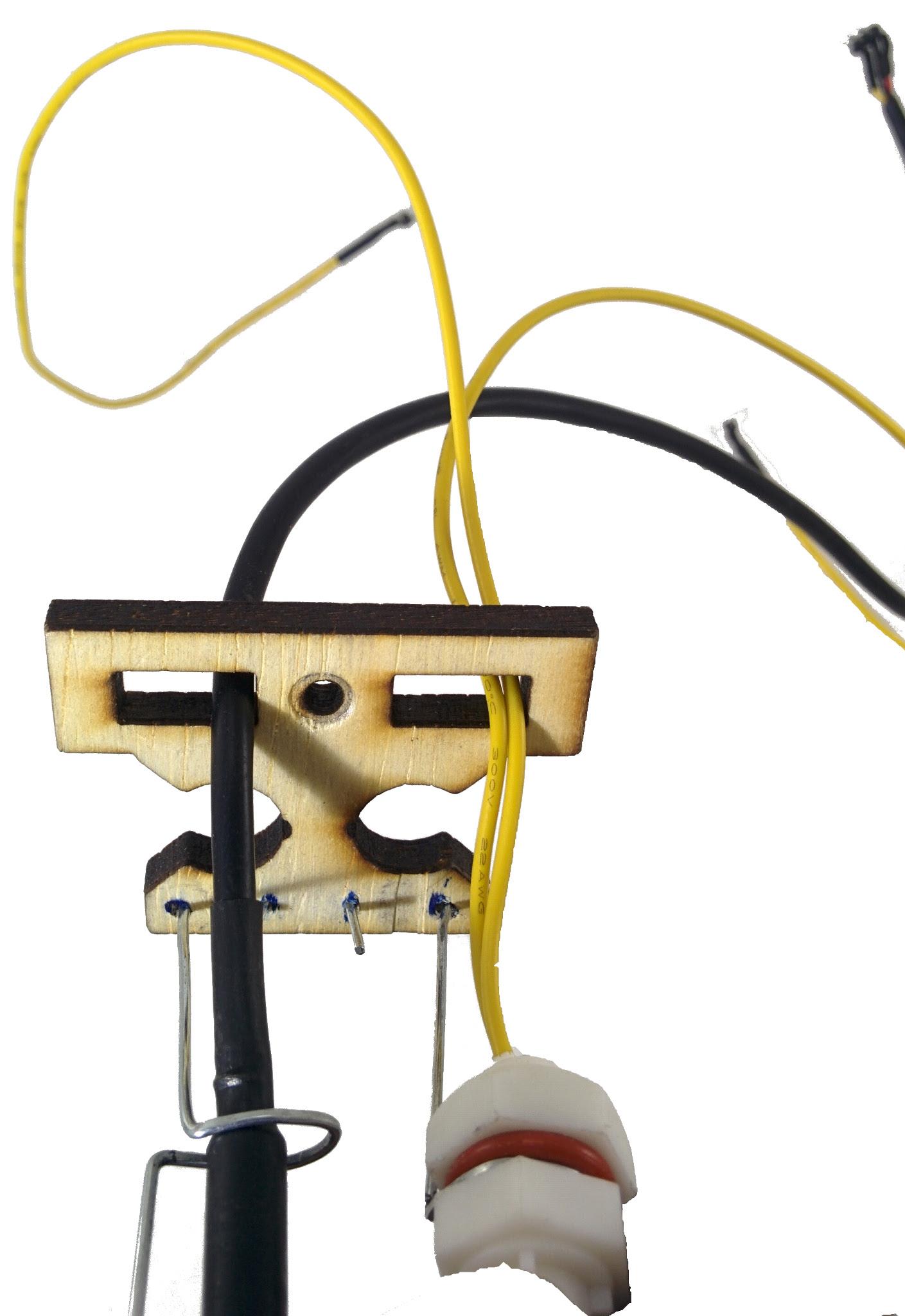

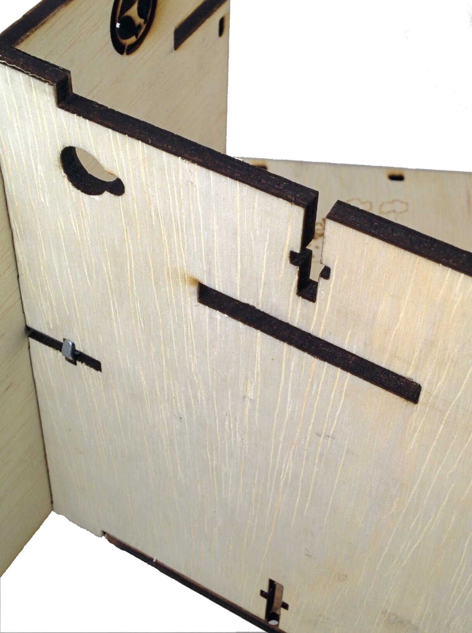
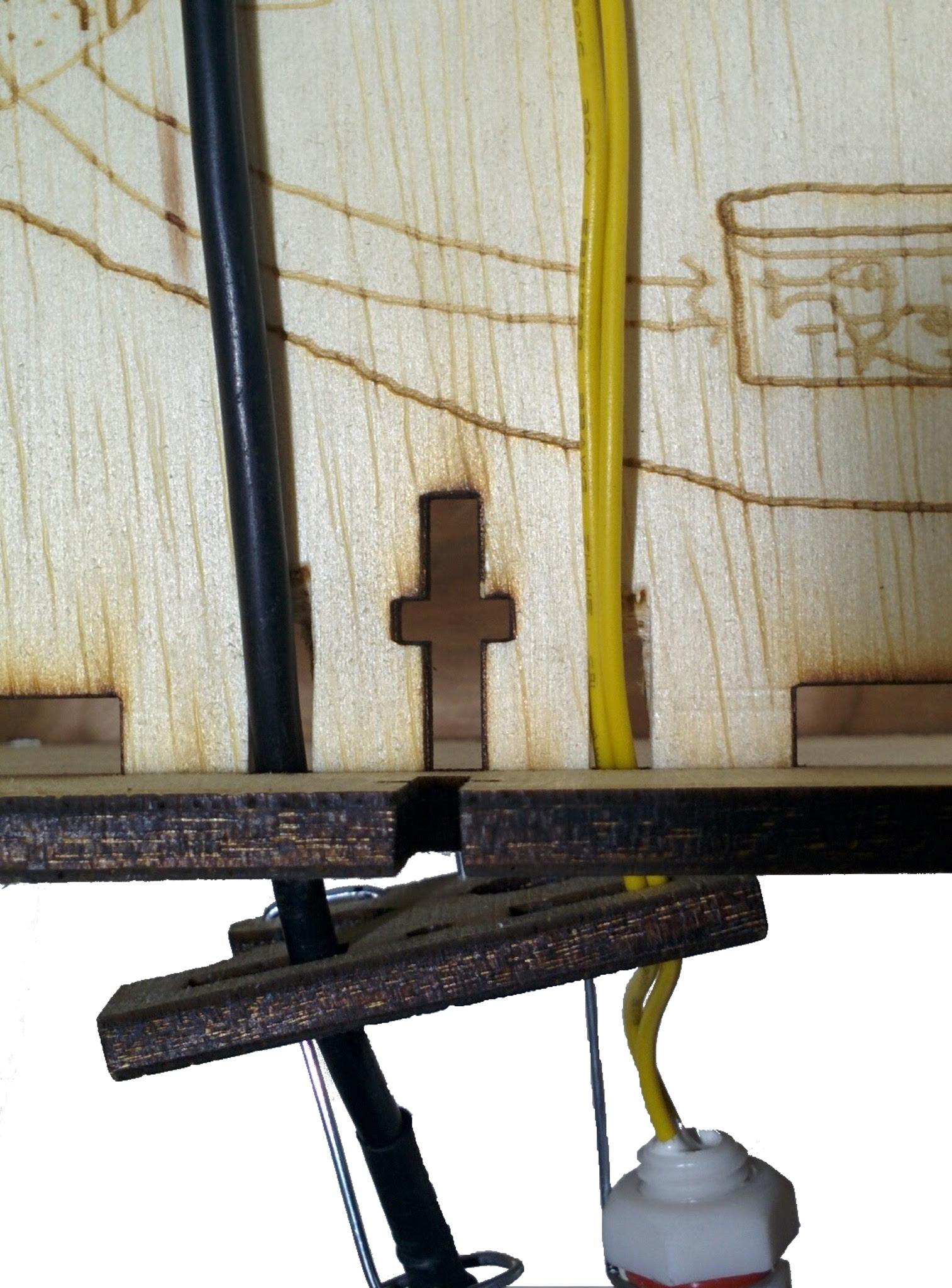
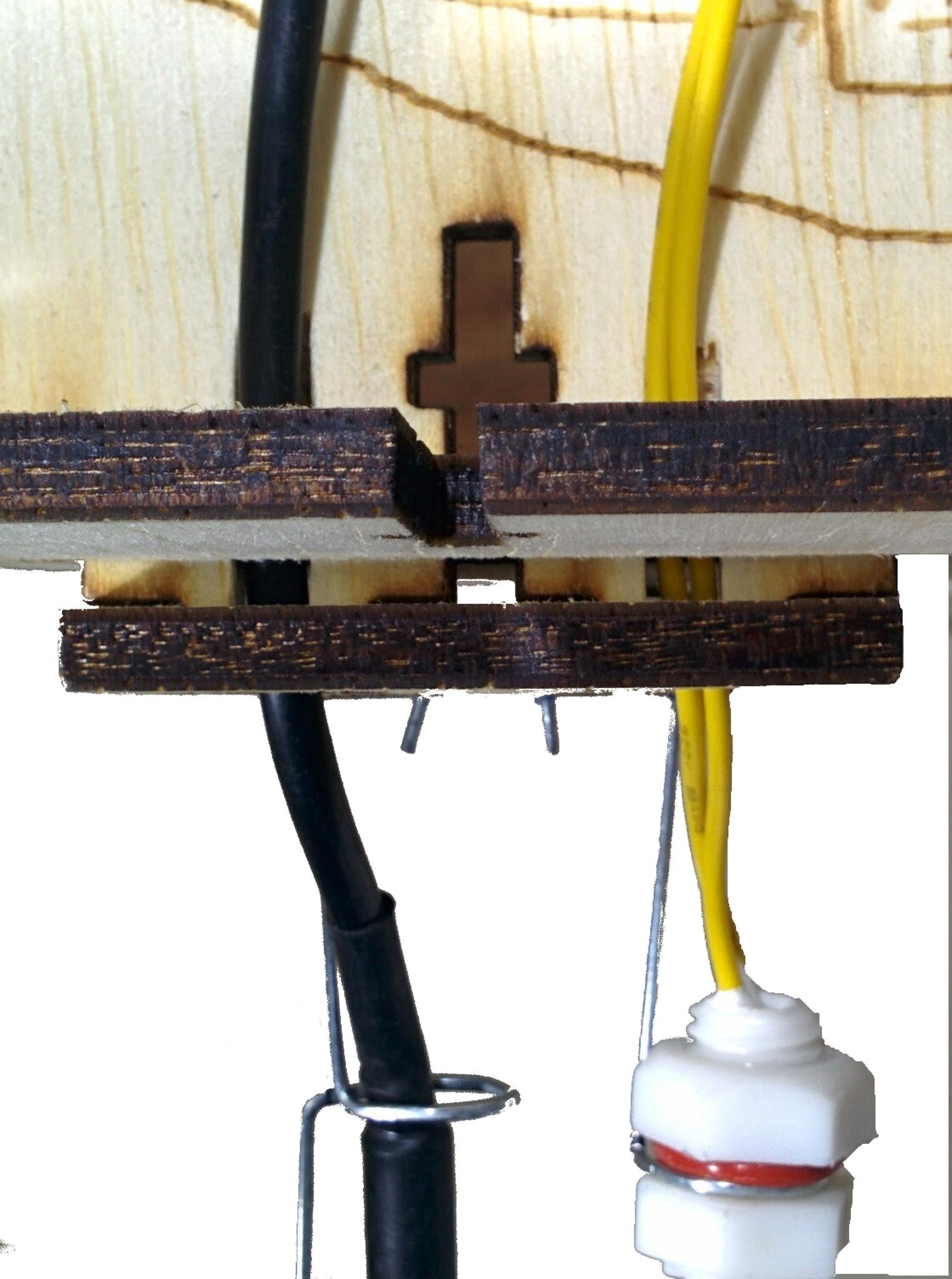
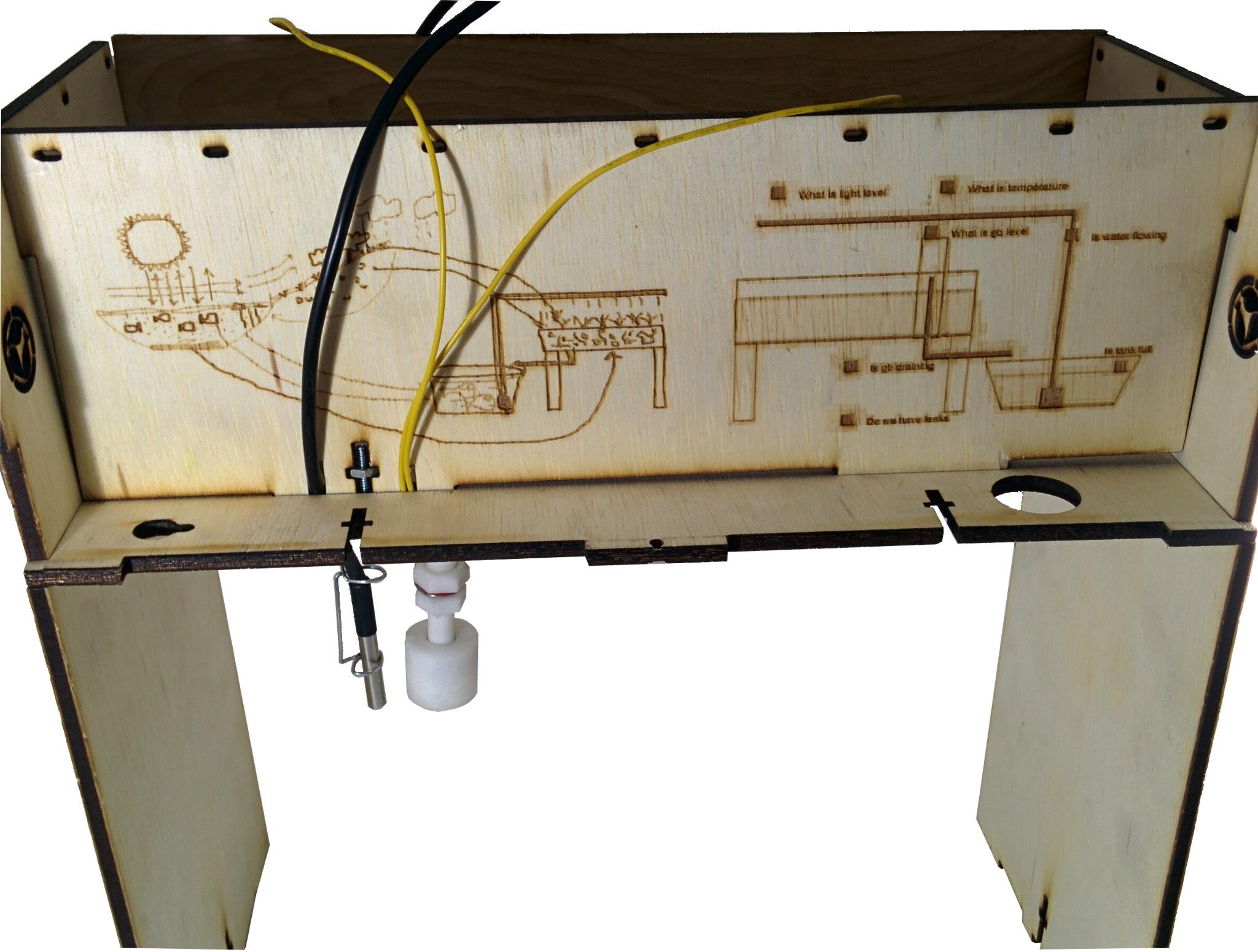
The tank sensor accessory mounts on the bottom of the storyboard. Push the sensor wires through the tank sensor adapter as shown. The tank sensor accessory mounts to the t-slot on the bottom of the storyboard panel shown. This slots into the bottom base panel in the section. Begin by pushing the sensor wires from the float switch and temperature switch through the bottom panel from the bottom. Bring the storyboard panel close into its position and make the sensor wires run along with the wire slots in the storyboard as shown. Push the storyboard in the base slot, and mount the tank sensor adapter. Then secure the sensor adapter to the storyboard at the bottom of the base panel using the hidden nut and bolt. This should look as shown below when mounted with the wires running on the inside (not the garden side) as shown.
V2 Garden Connection Schematic
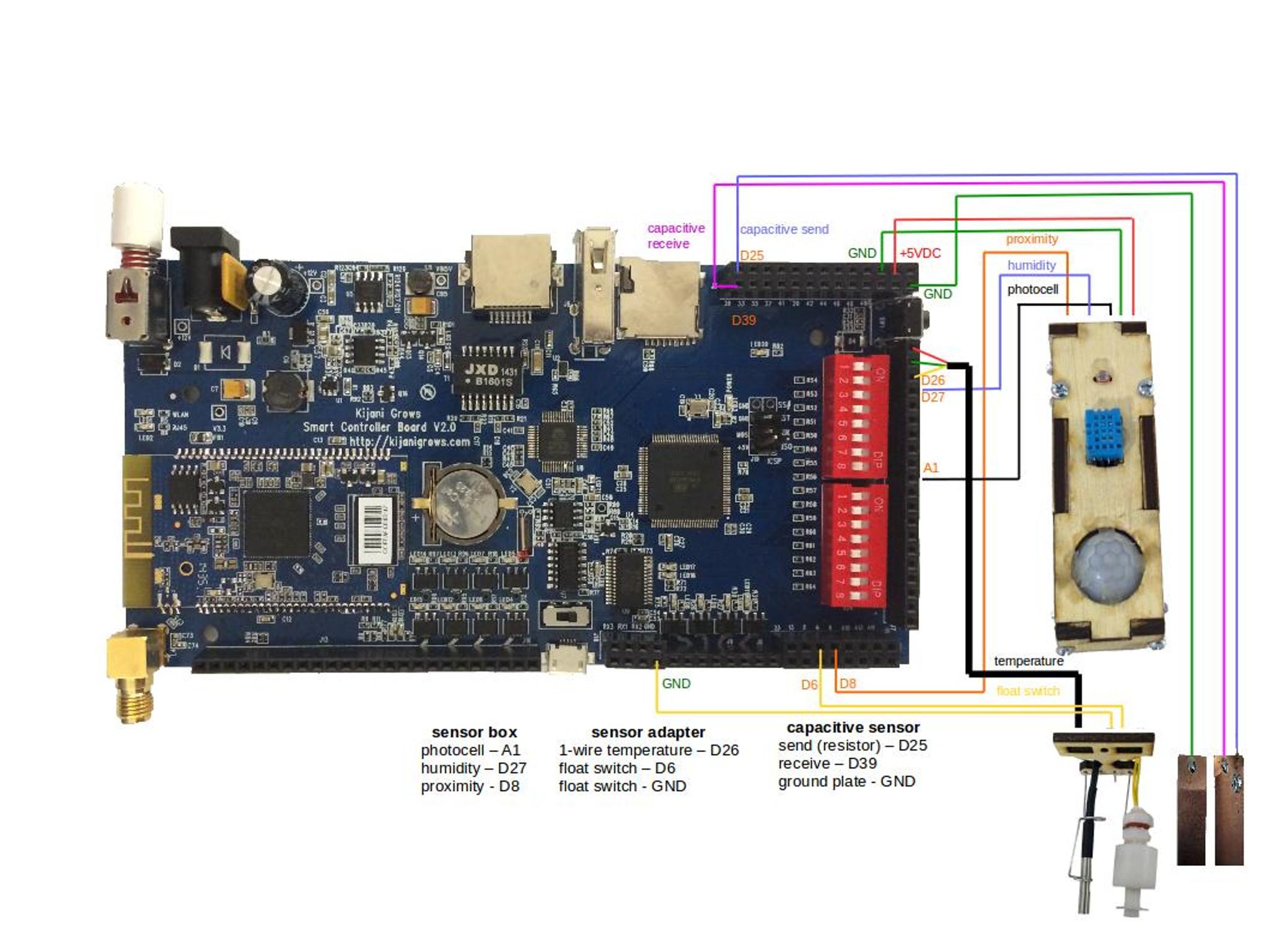
The V2 controller, garden sensor schematic is shown pin connections shown..
V2 Sensors Pin Out
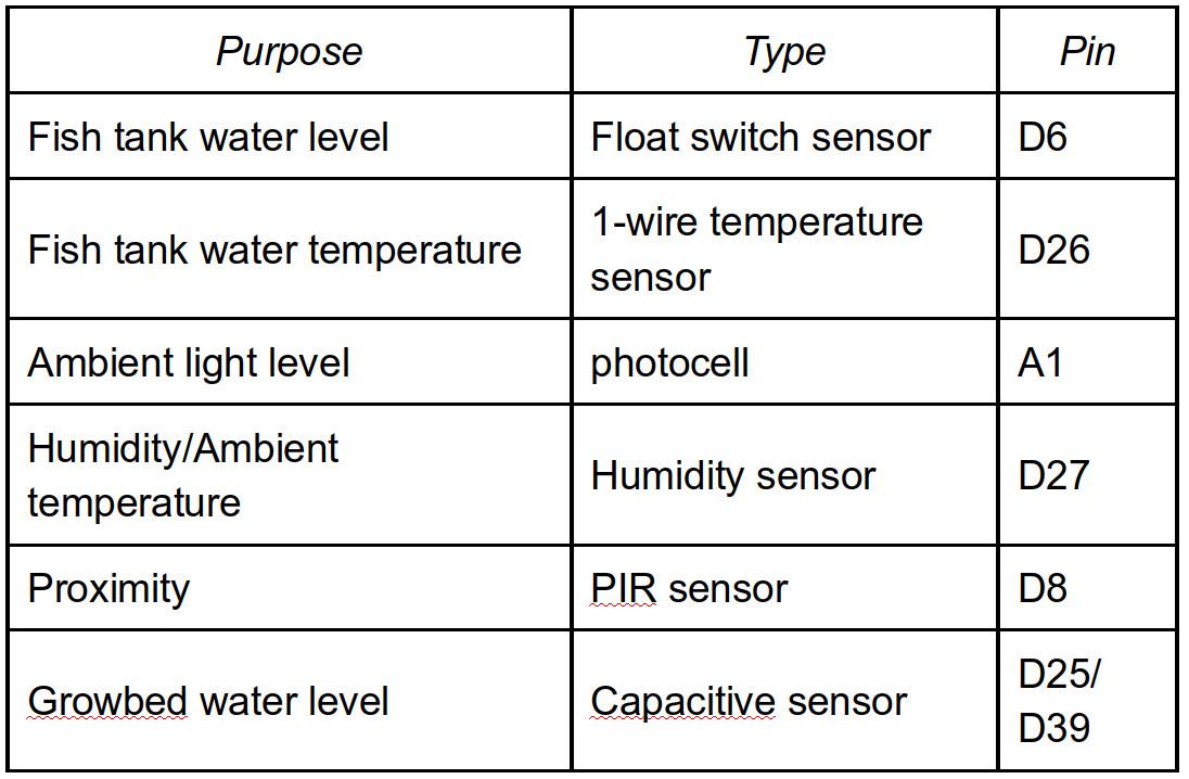
The sensor pin connections shown above on the v2 board are indicated in the table.
Sensor Box Connections
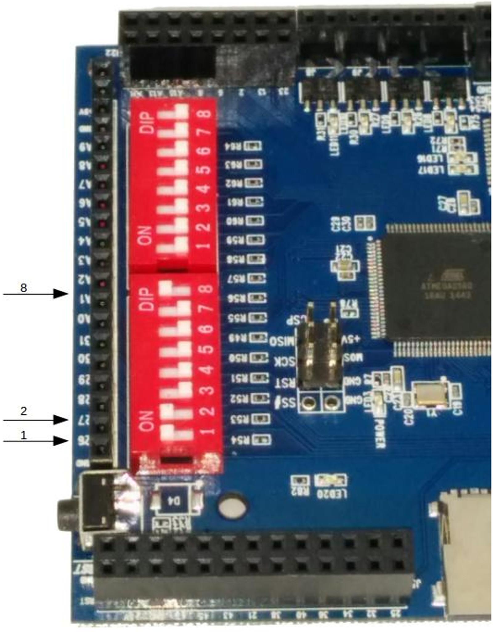
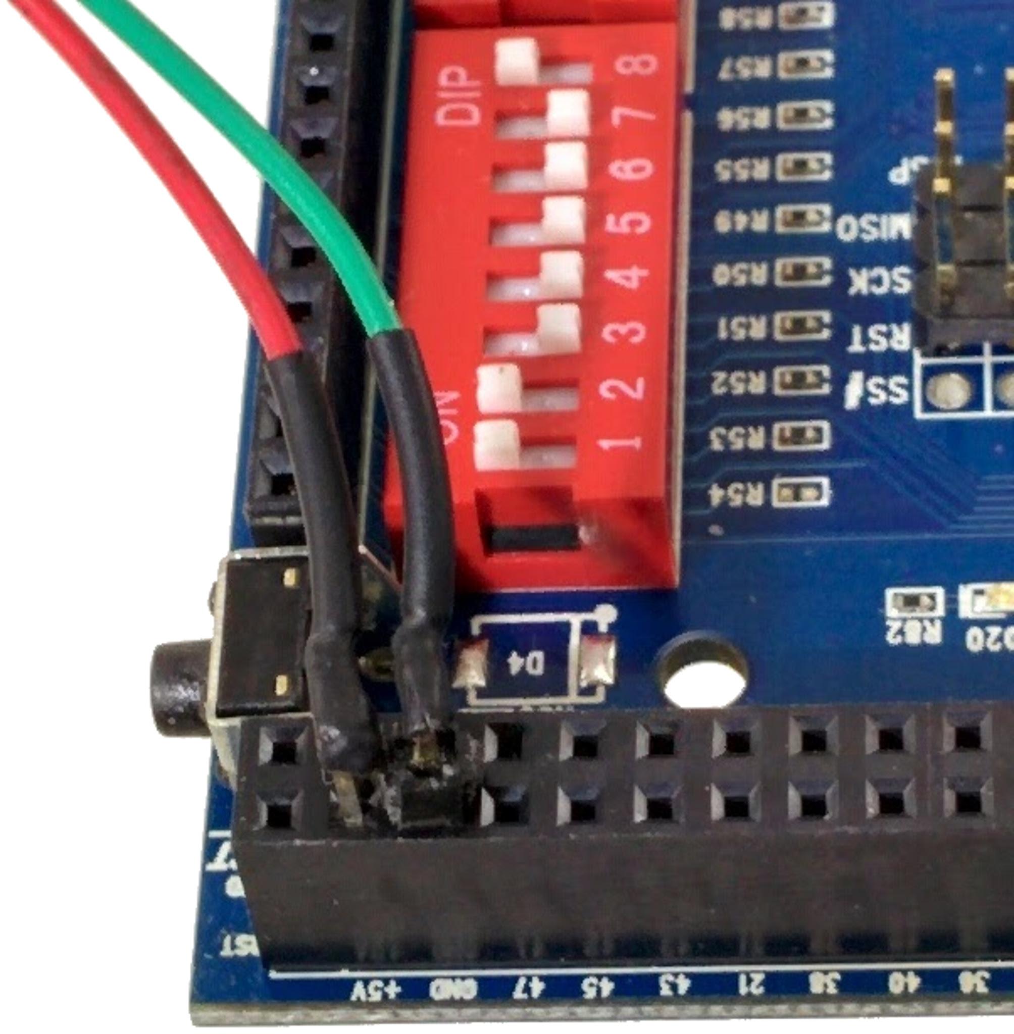
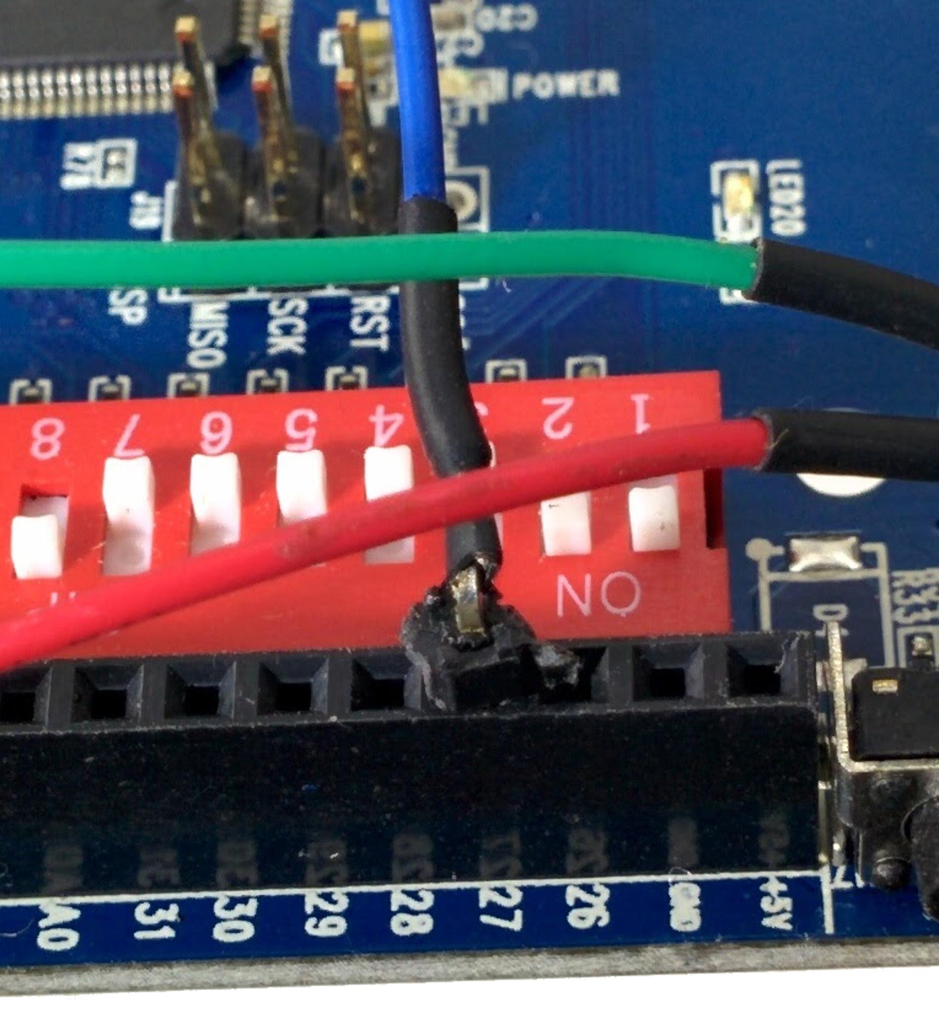
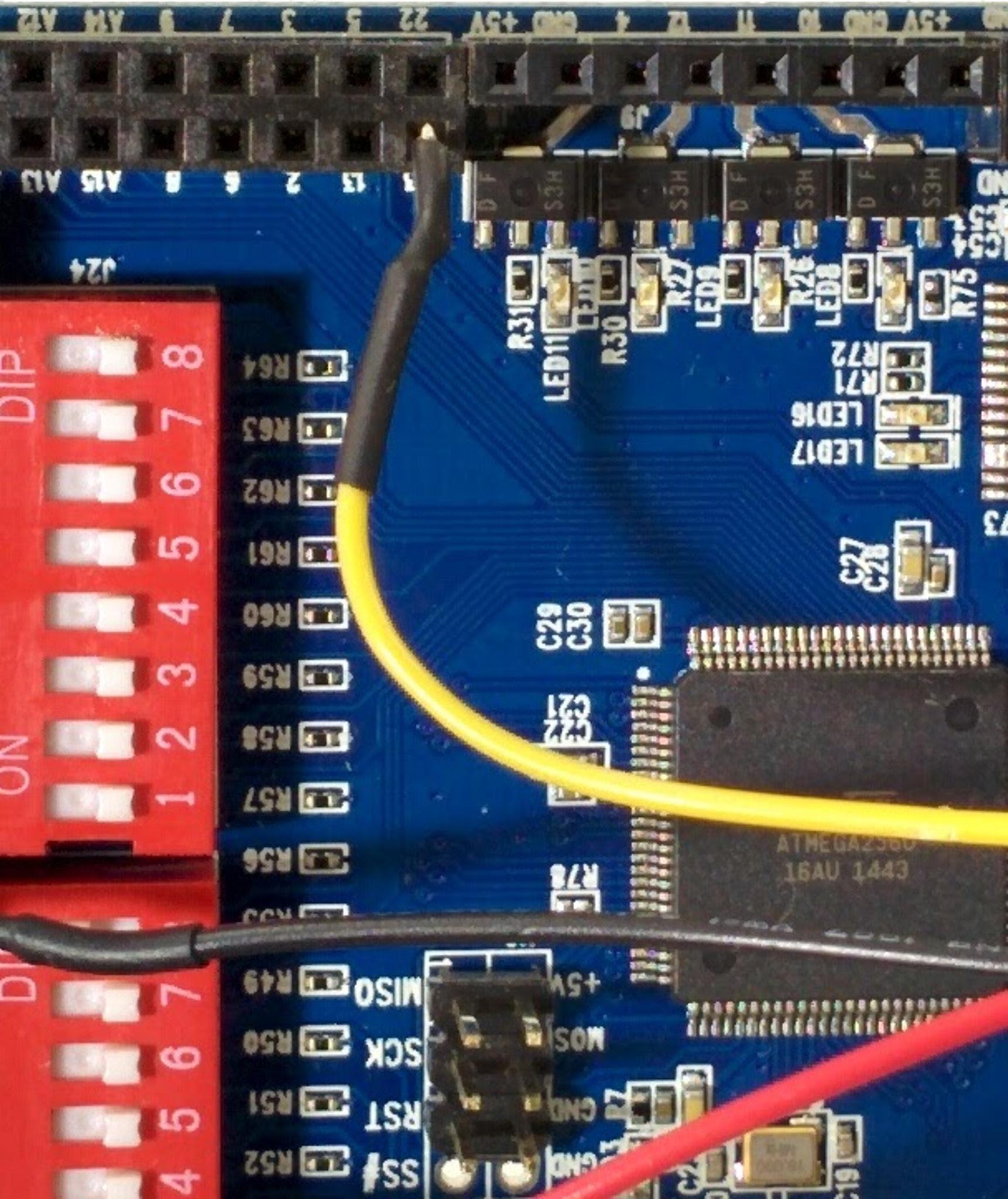
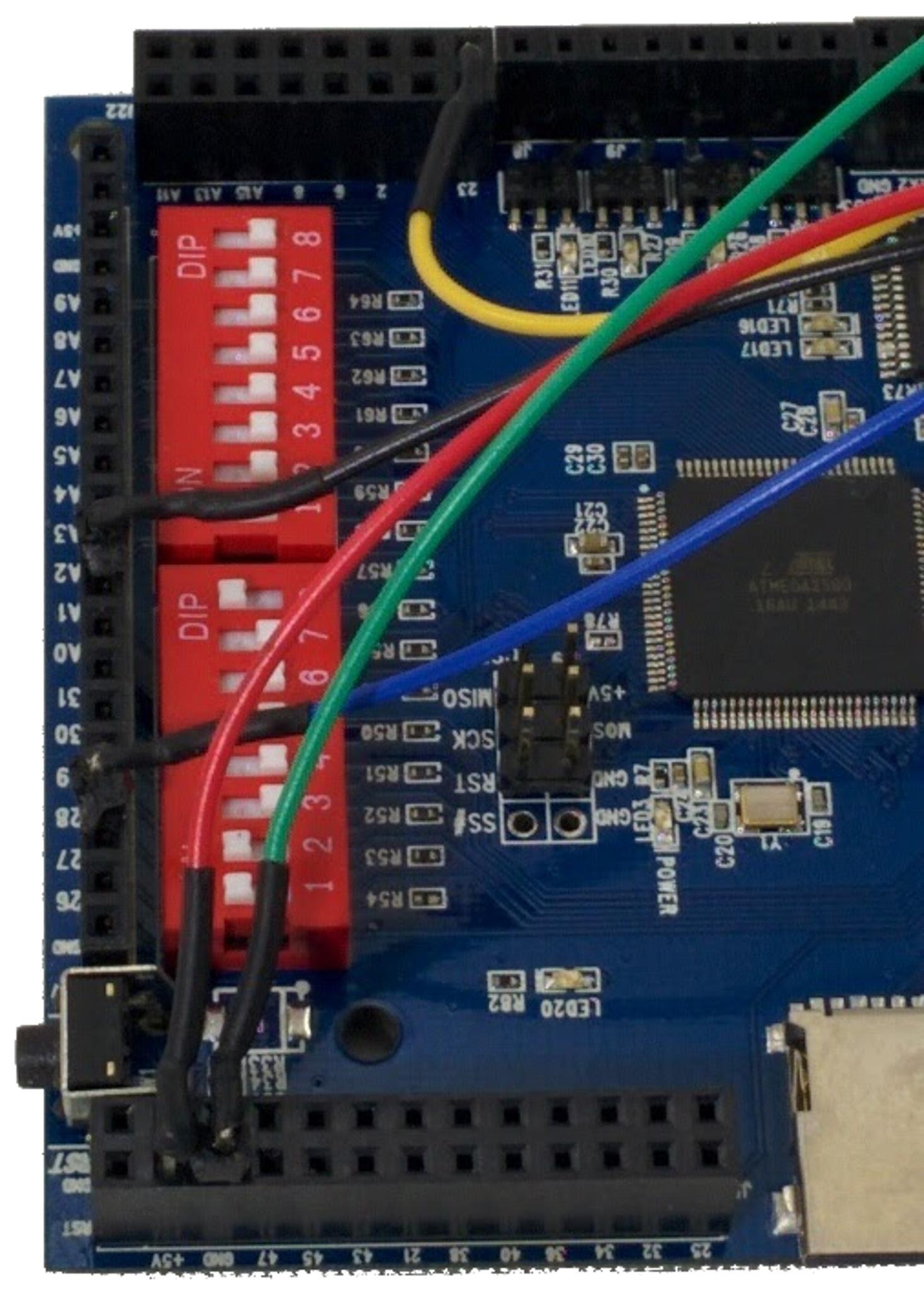
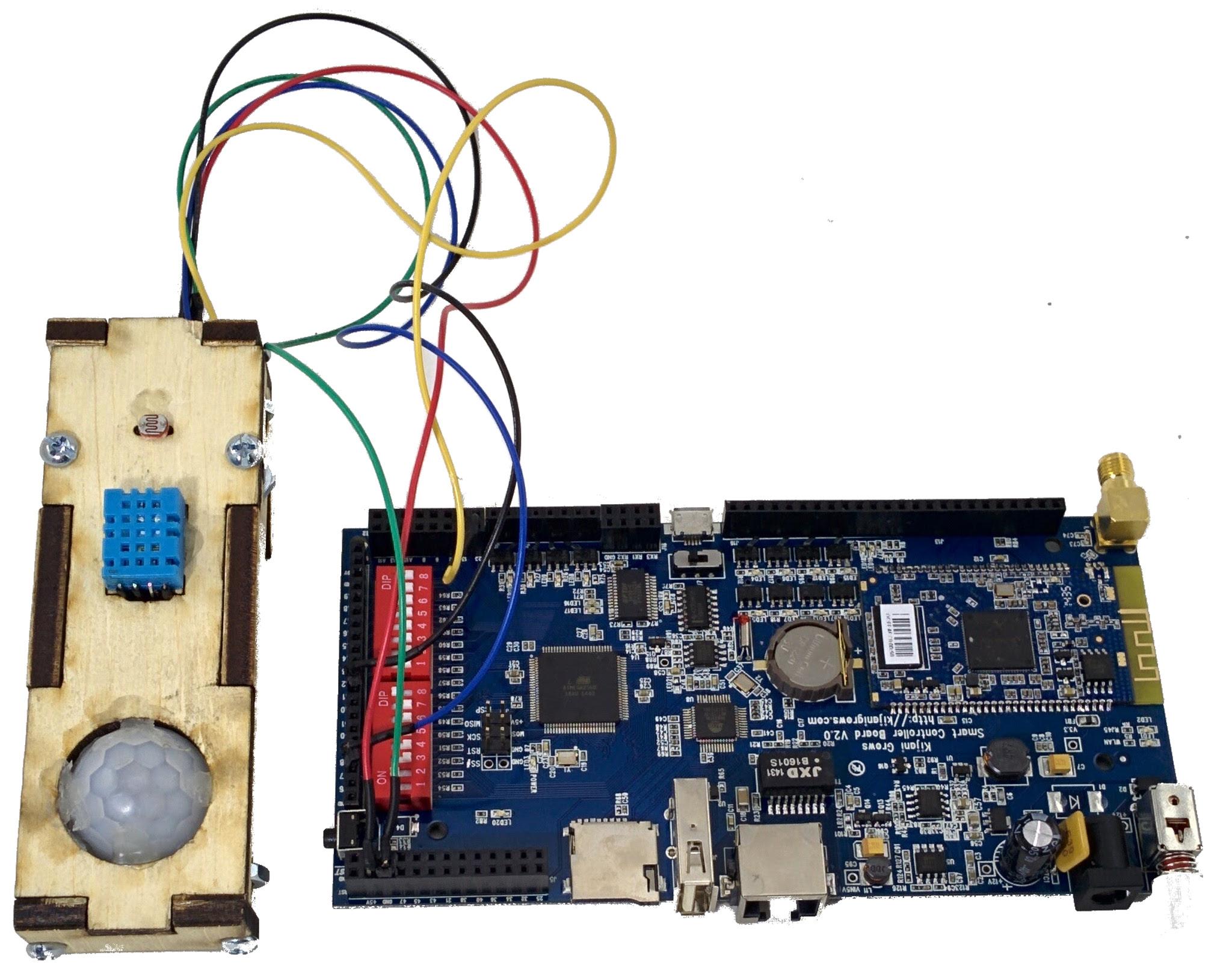
The following steps for connecting the sensors are done without the enclosure shown for clarity. Start by configuring the dip switches - flick switches 1,2,8 to the ON position as shown. Connect the sensor box power lines to the v2 controller on any +5V and GND as shown. Connect the humidity sensor wire to pin 27 as shown. Next, we connect the proximity sensor to pin 6. Well, the diagram below shows the connection on pin 23, shift this to pin 6. The point is it does not matter so long as it is a free pin, we configure them all the same way, as will be seen in a bit. The sensor box wiring for power and 3 data lines is shown below. The completed v2 controller and wired sensor box is shown
Connecting the Tank Sensor Adapter
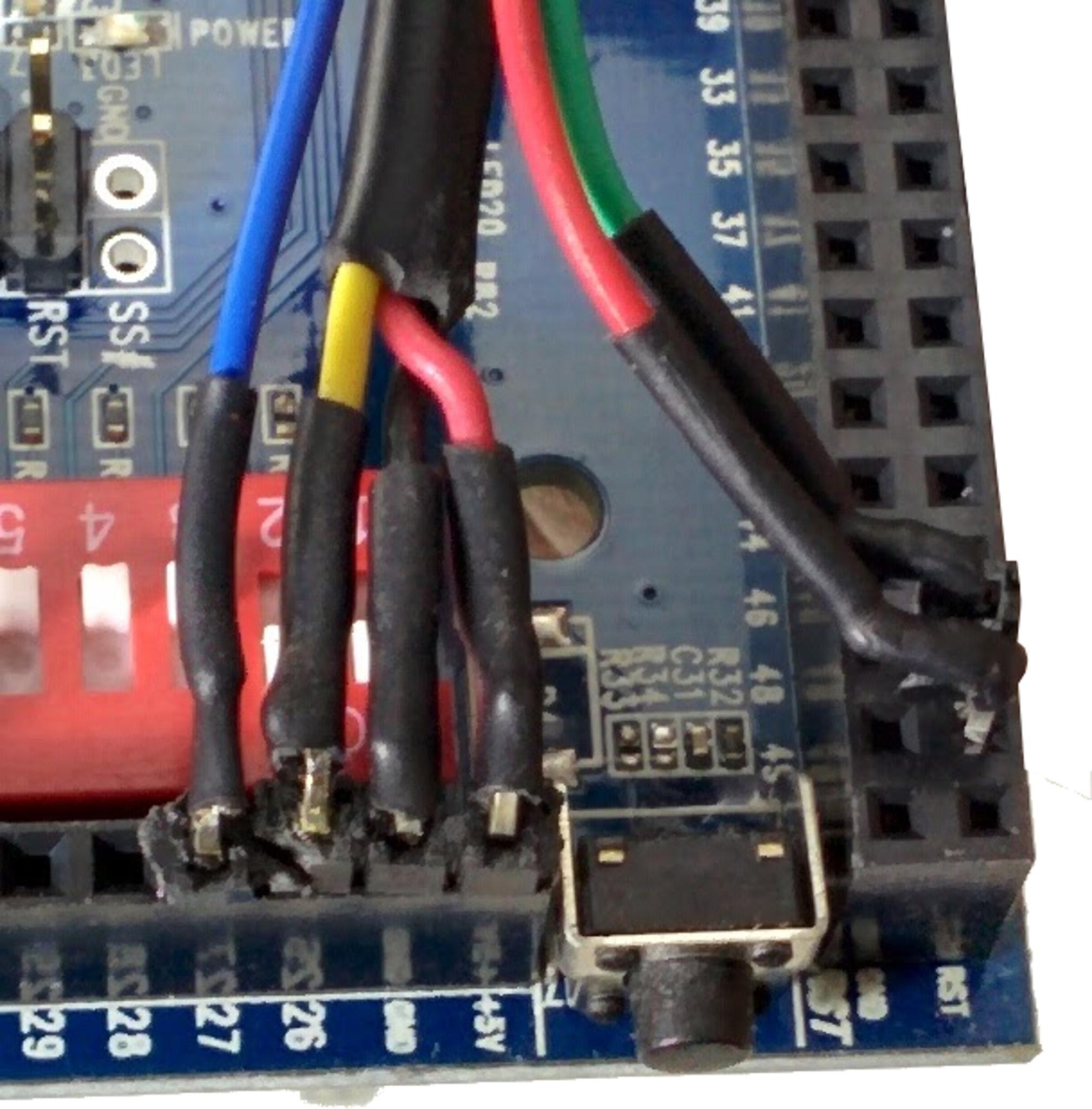
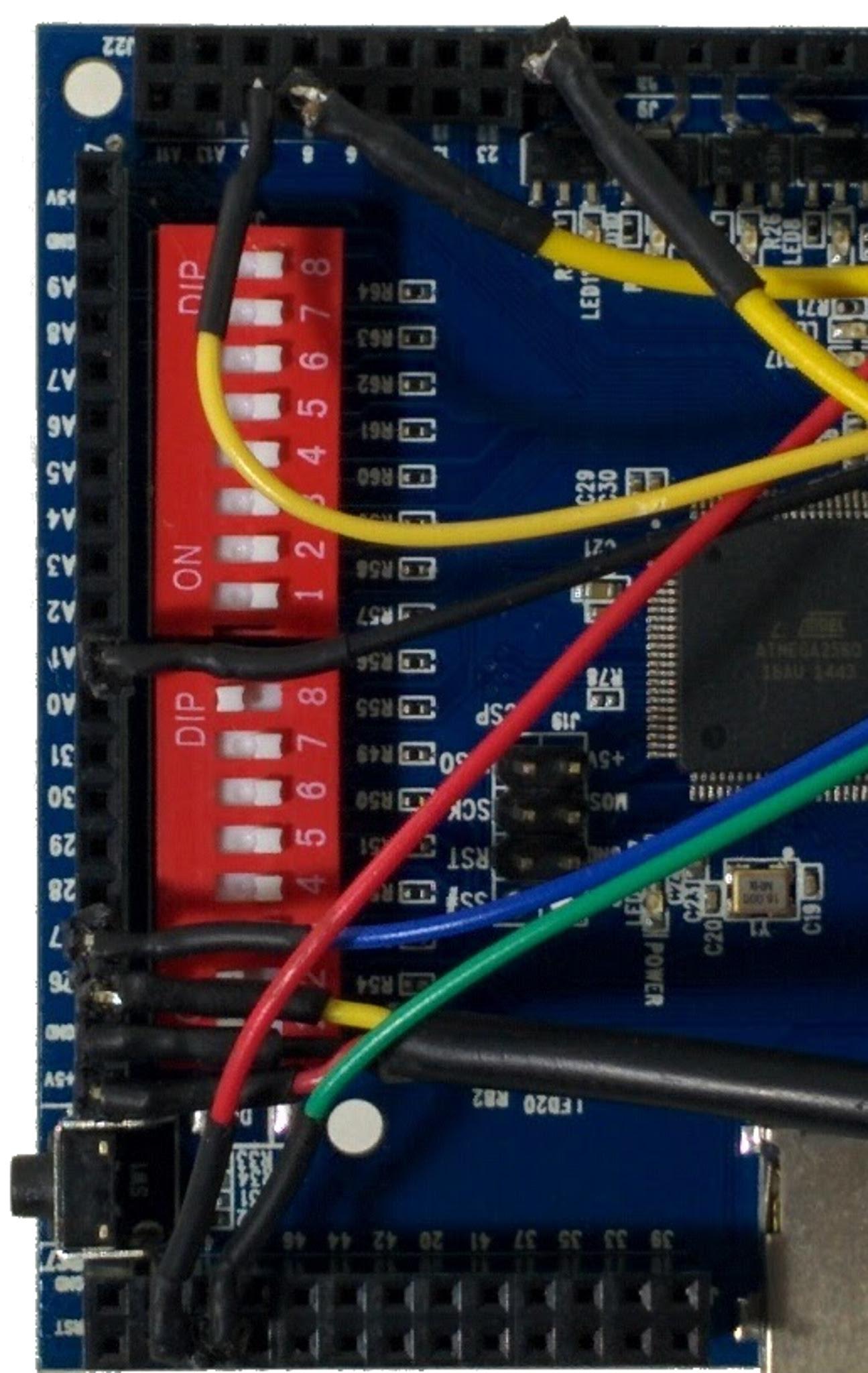
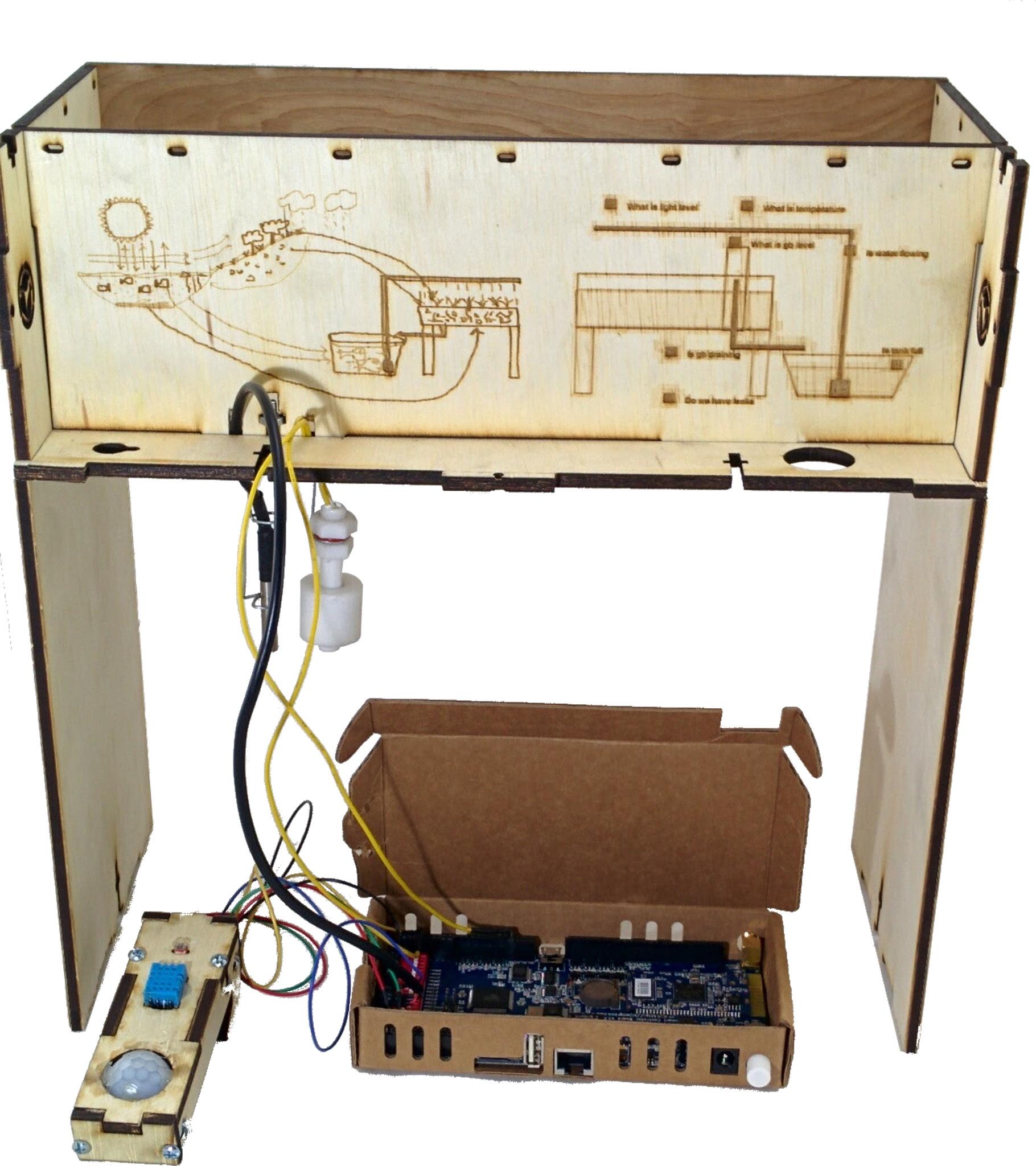
Next, we wire the tank sensors to the v2 controller starting with the fish tank temperature sensor on pin D26, +5V, and GND as shown. Next connect one of the wires from the float switch to D8 and the other to any ground, such as the GND next to D23 as shown. The garden, sensor box, tank sensors, and v2 enclosure with the front panel removed are shown below
Mounting the Sensor Box
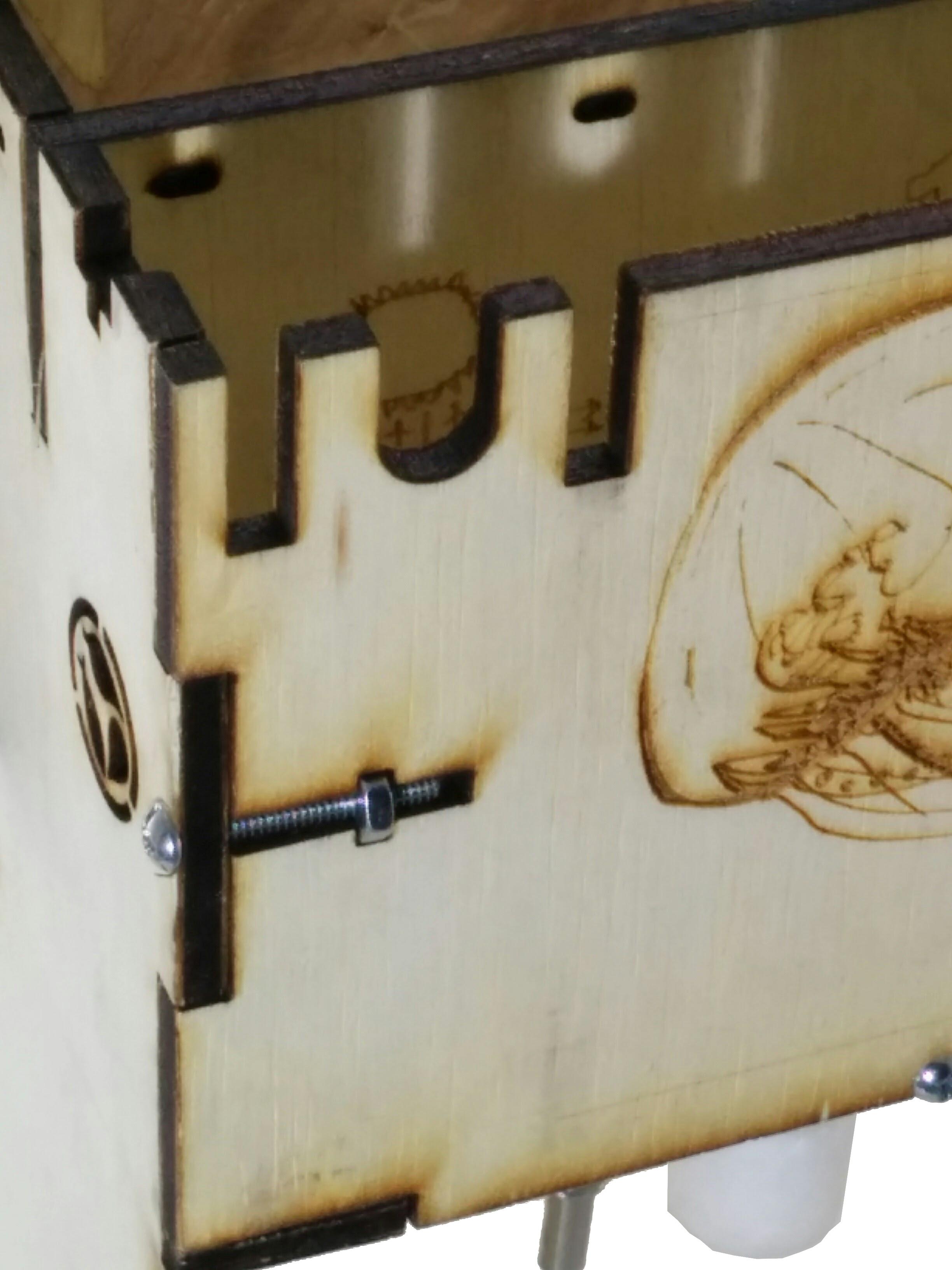
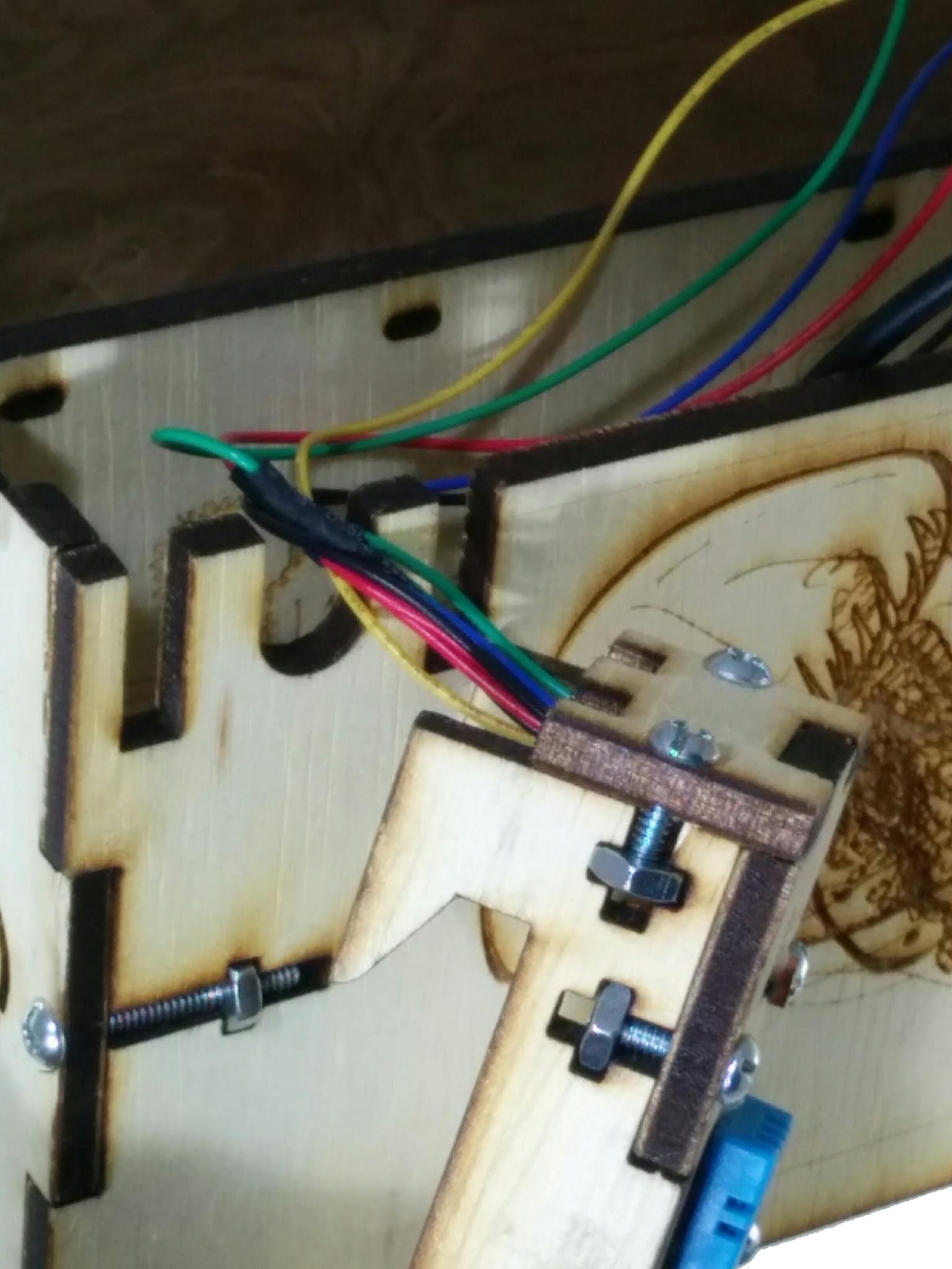
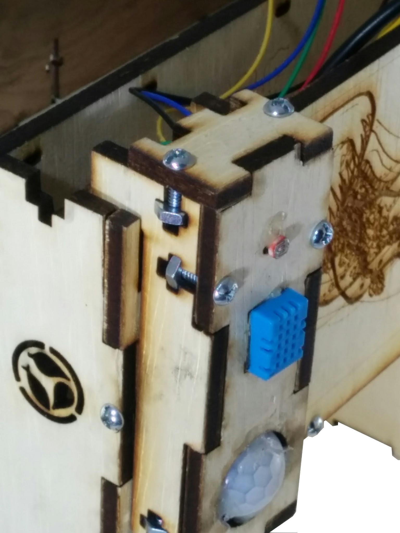
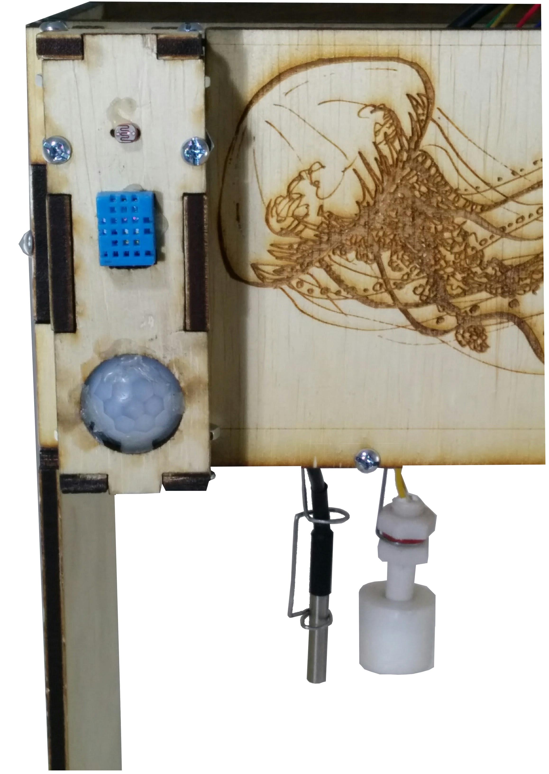
The sensor mounts onto the front panel using the slots shown. The sensor box is shown by the attachment, the hooks slide into the holes while the wires from the box will run through the middle slot as shown. This is inserted from the top and slides straight down as shown. Push gently yet firming until it is completely inserted as shown below
Mounting the V2 Enclosure
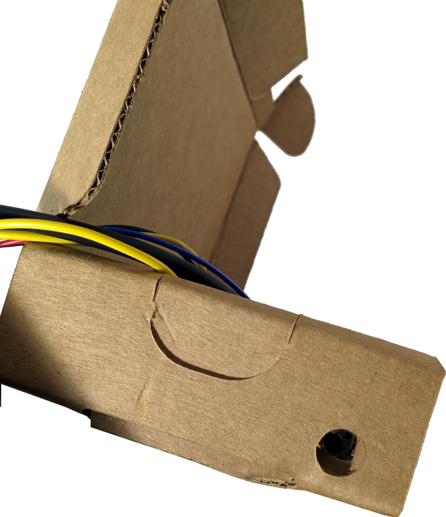
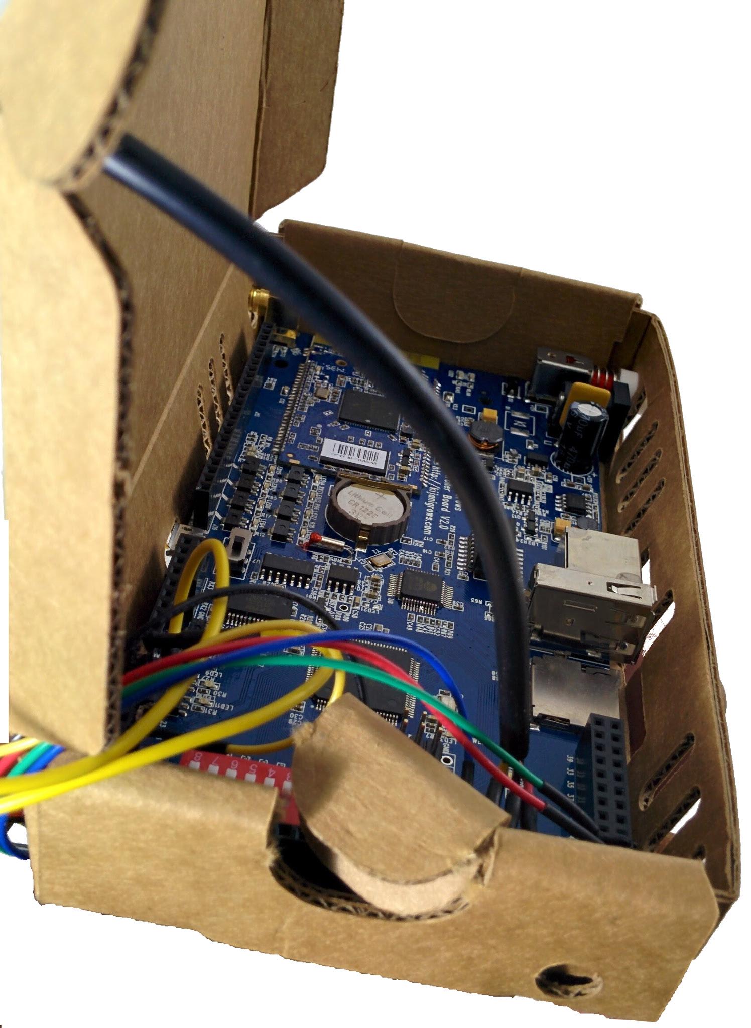
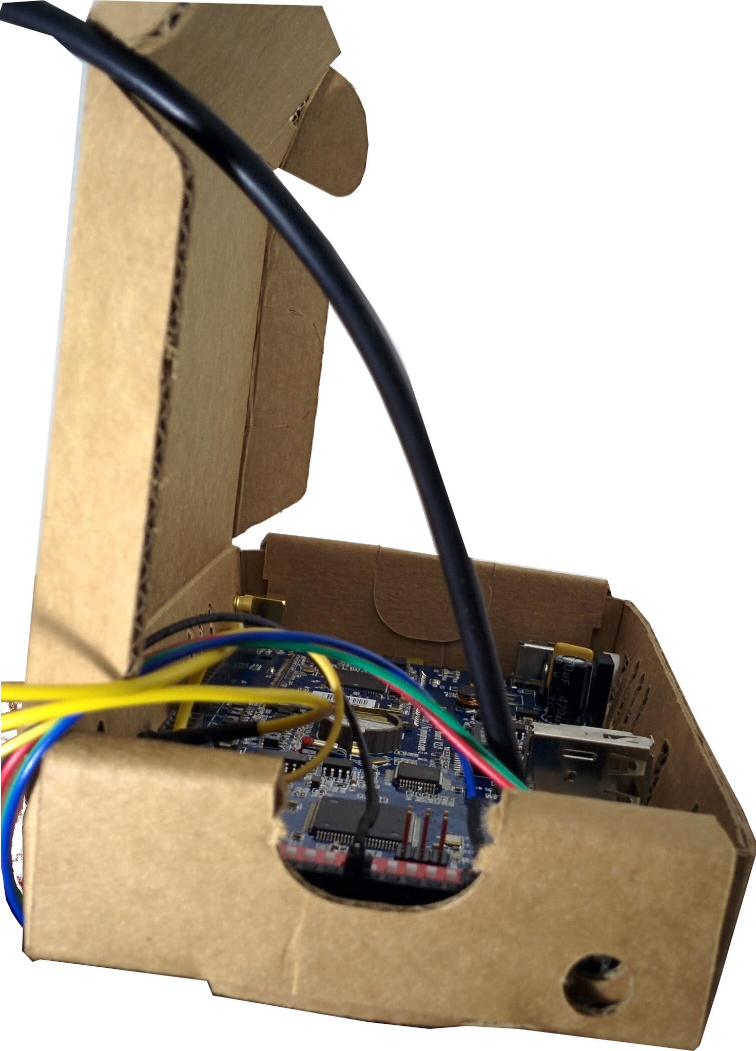
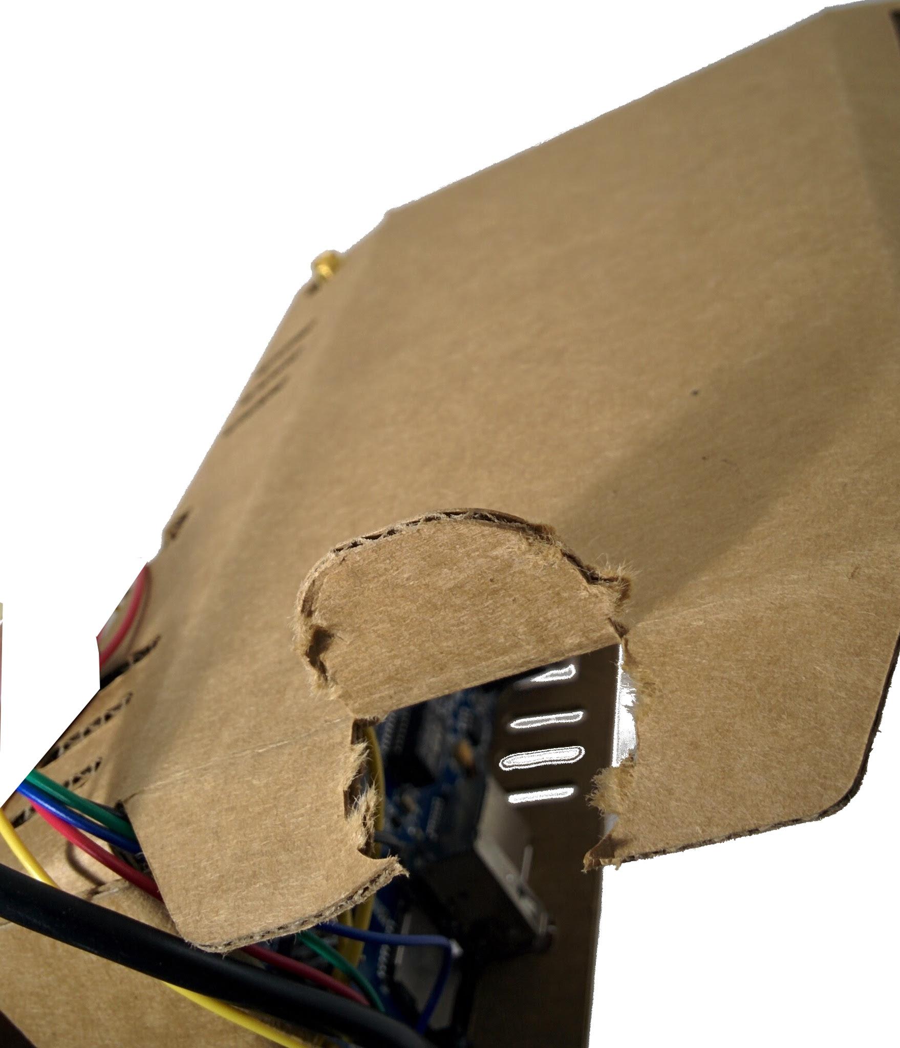
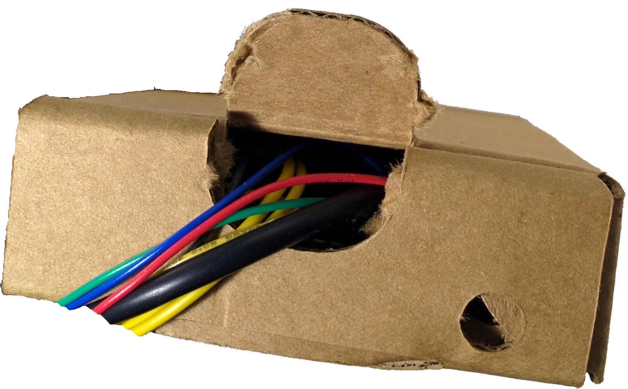
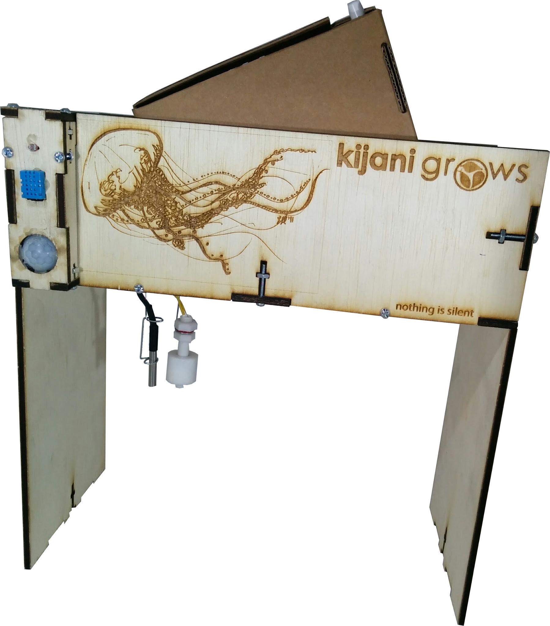
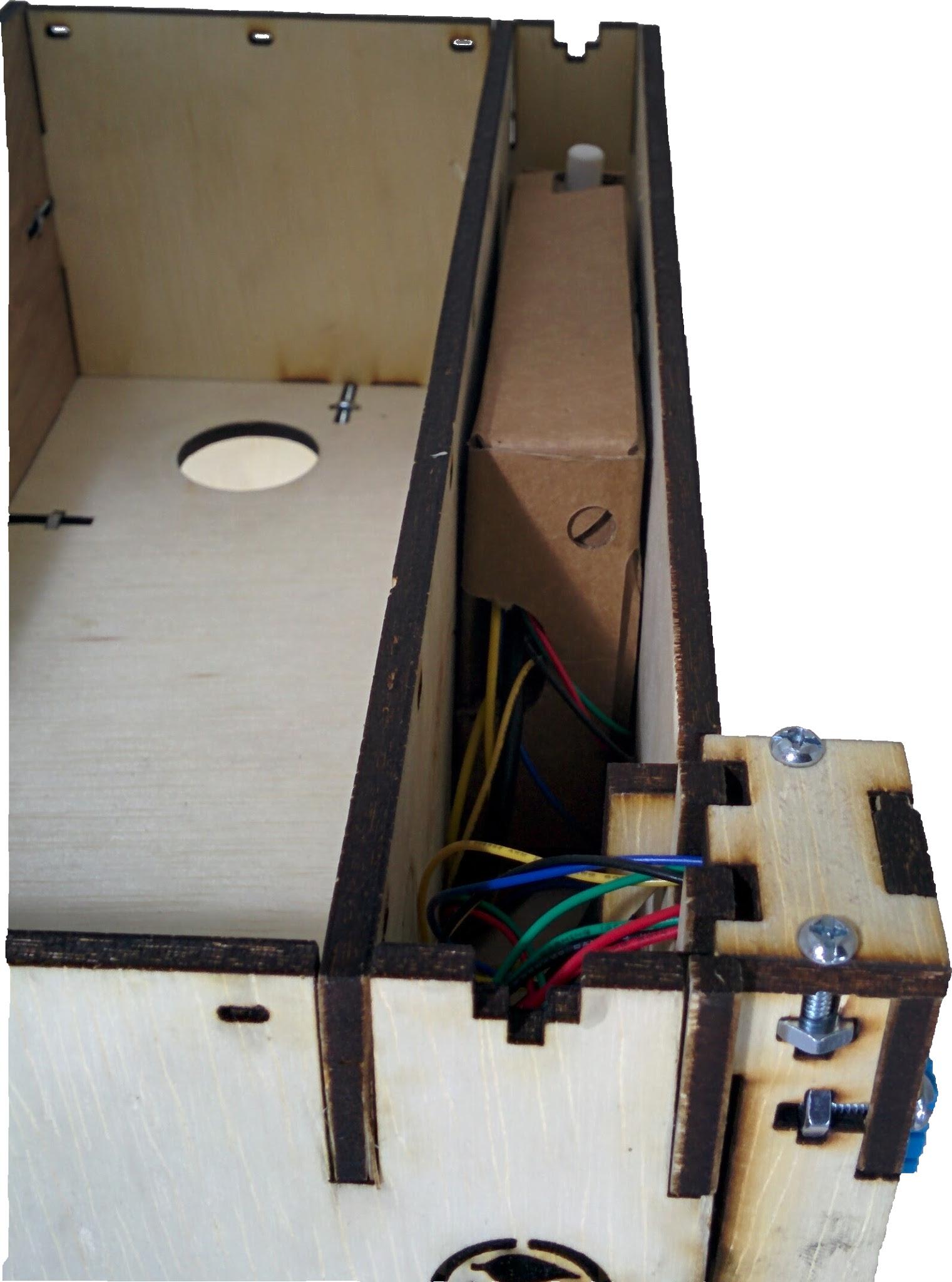
Now we can run the wires through the enclosure. We start by tearing off the slot next to the reset switch as shown. Rip this part off as shown. The wire opening is shown. Tear open the sides of the flap on the top side as shown. Shut the enclosure with the flap on the inside or outside as shown. Insert the wired enclosure into the control cavity in the garden as shown. The controller is shown inserted into the control slot.
Completing the Irrigation
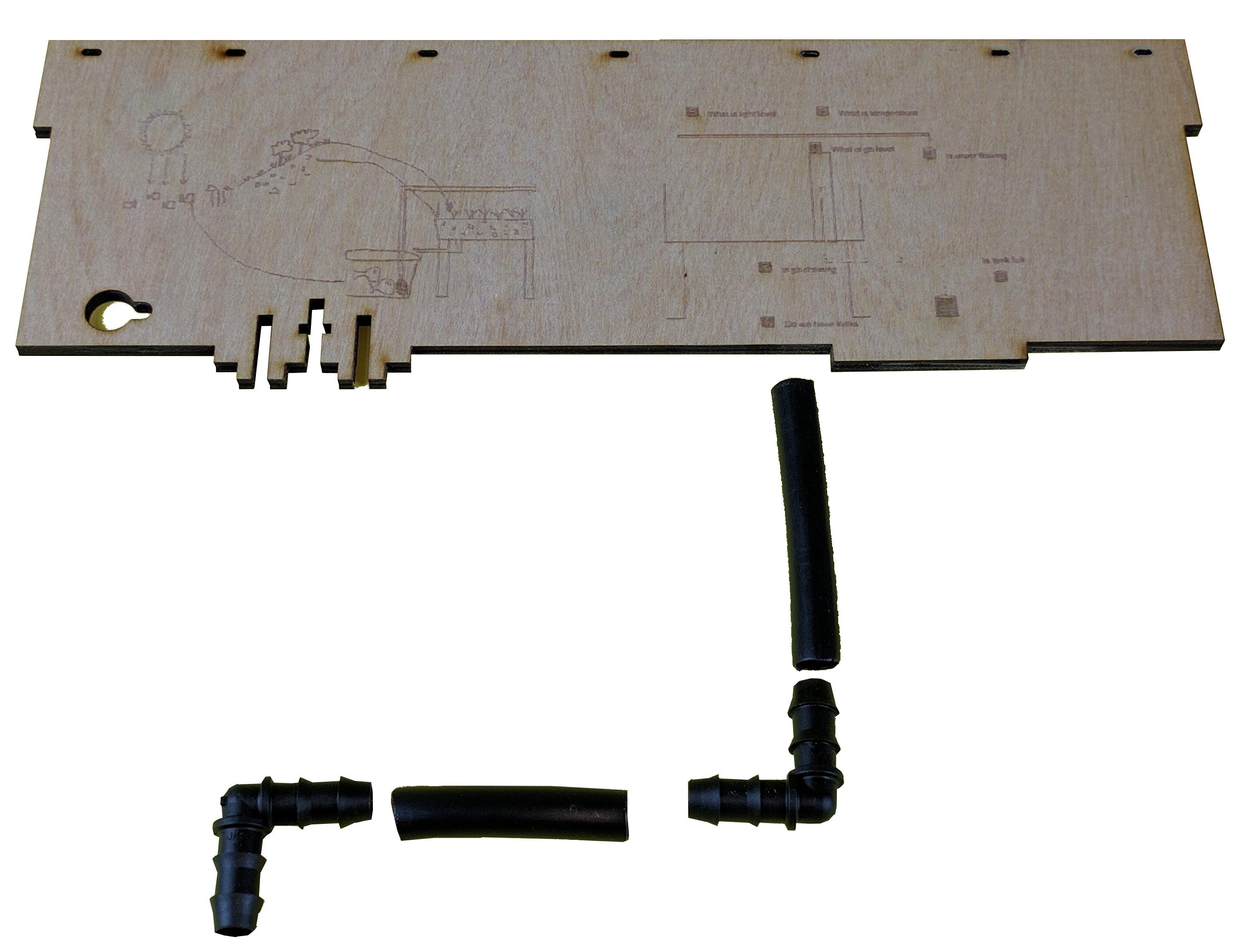
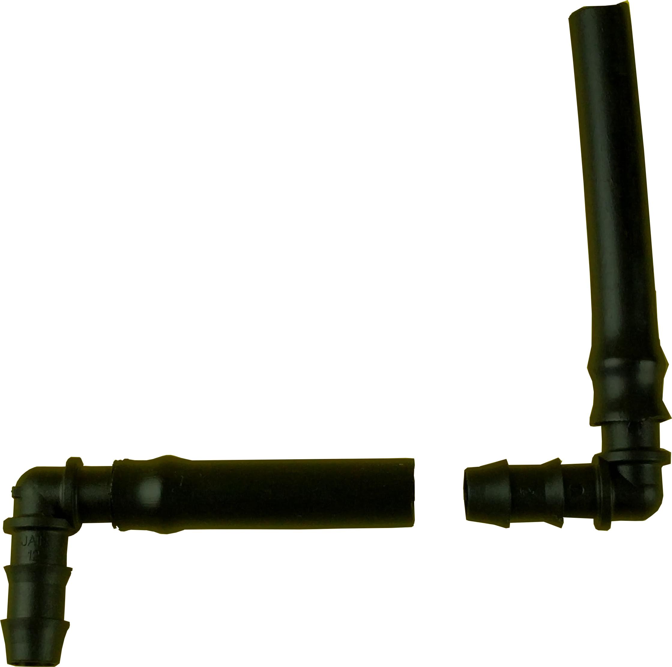
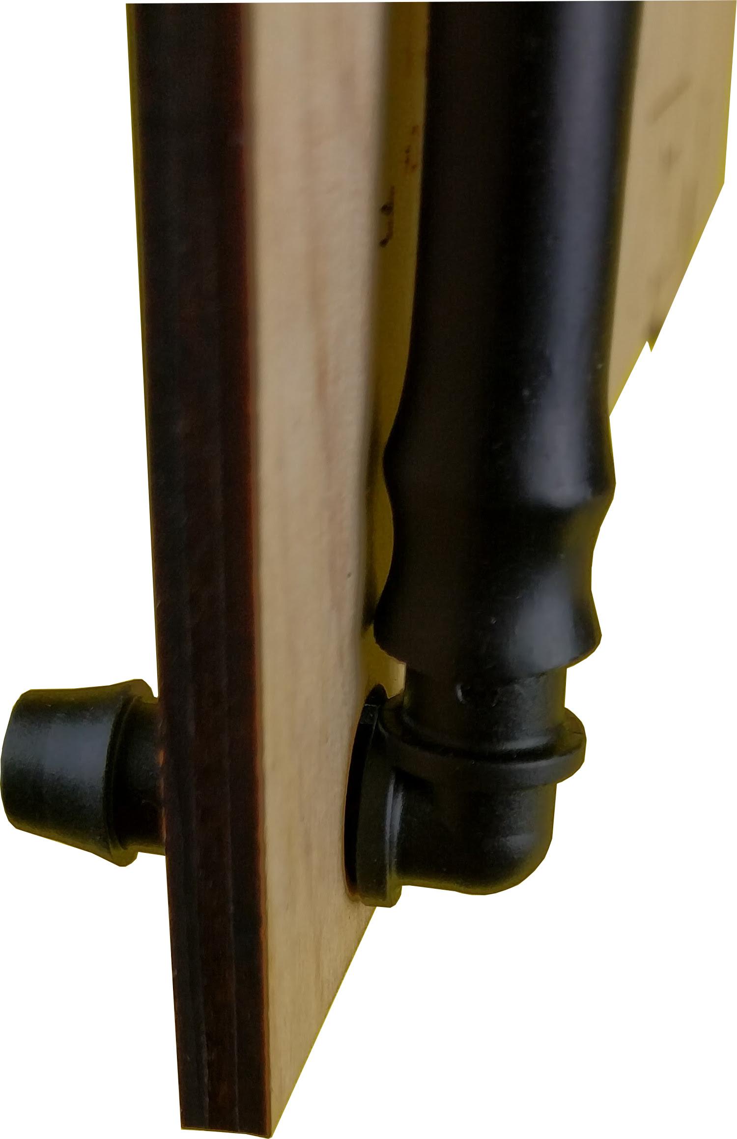
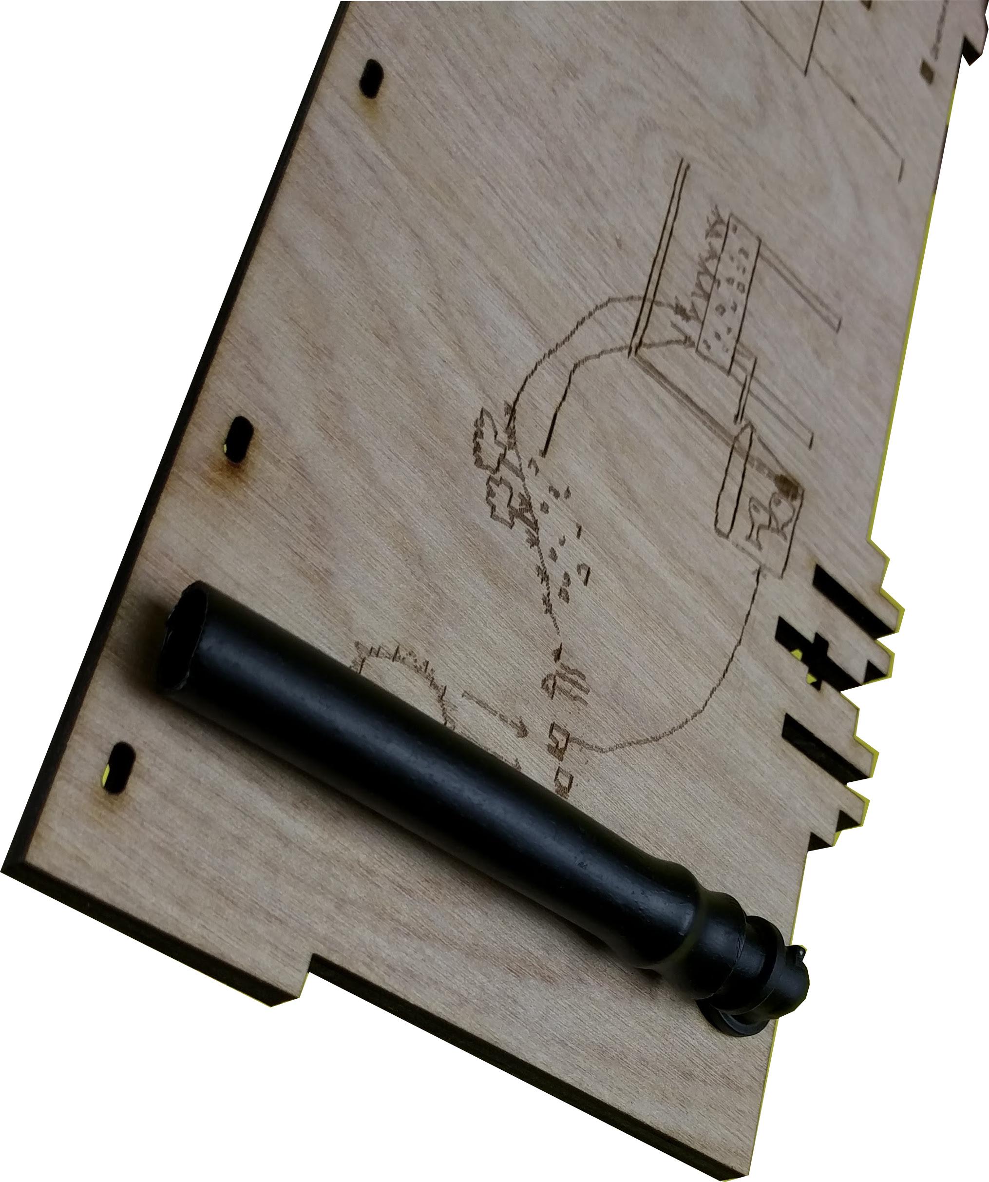
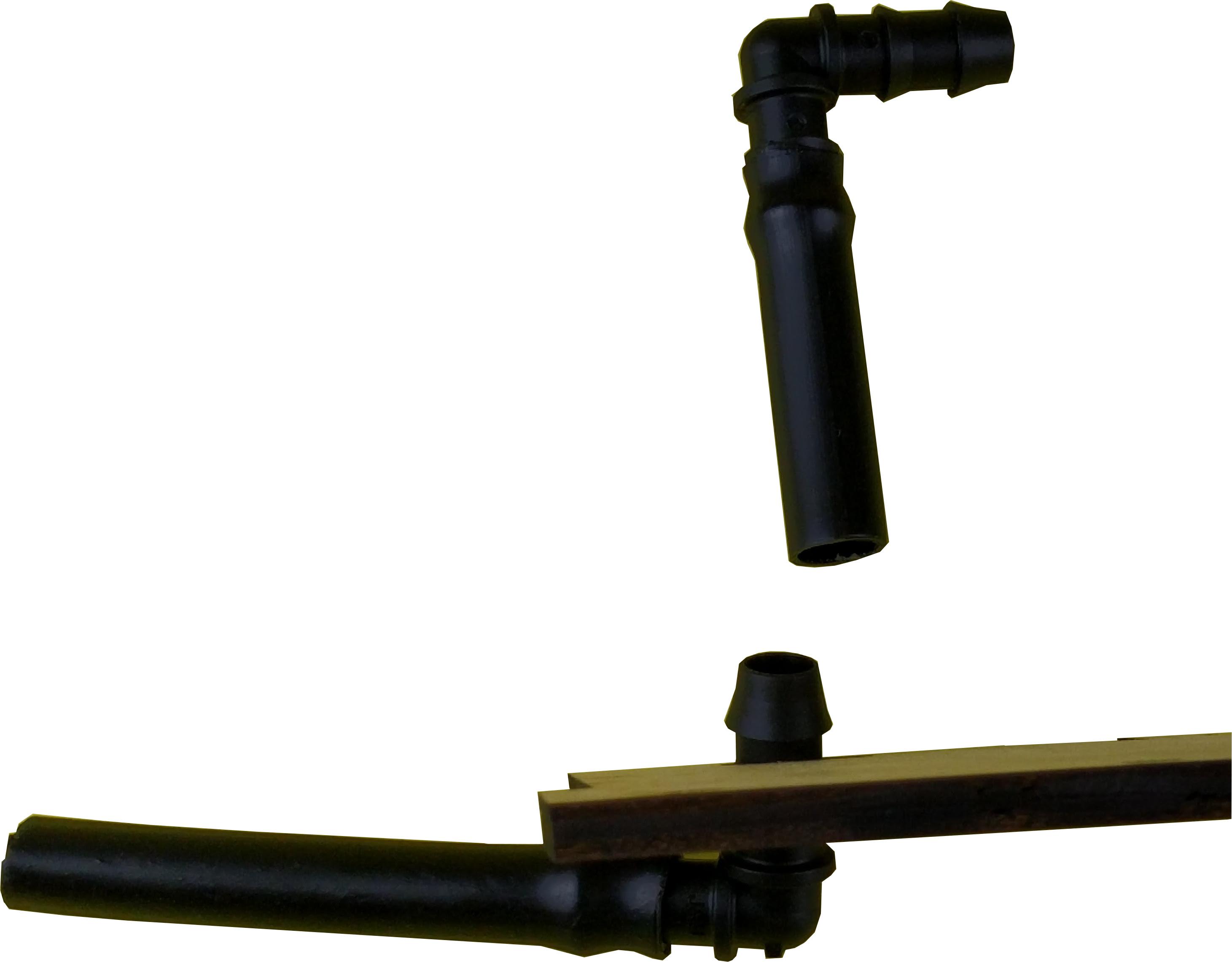
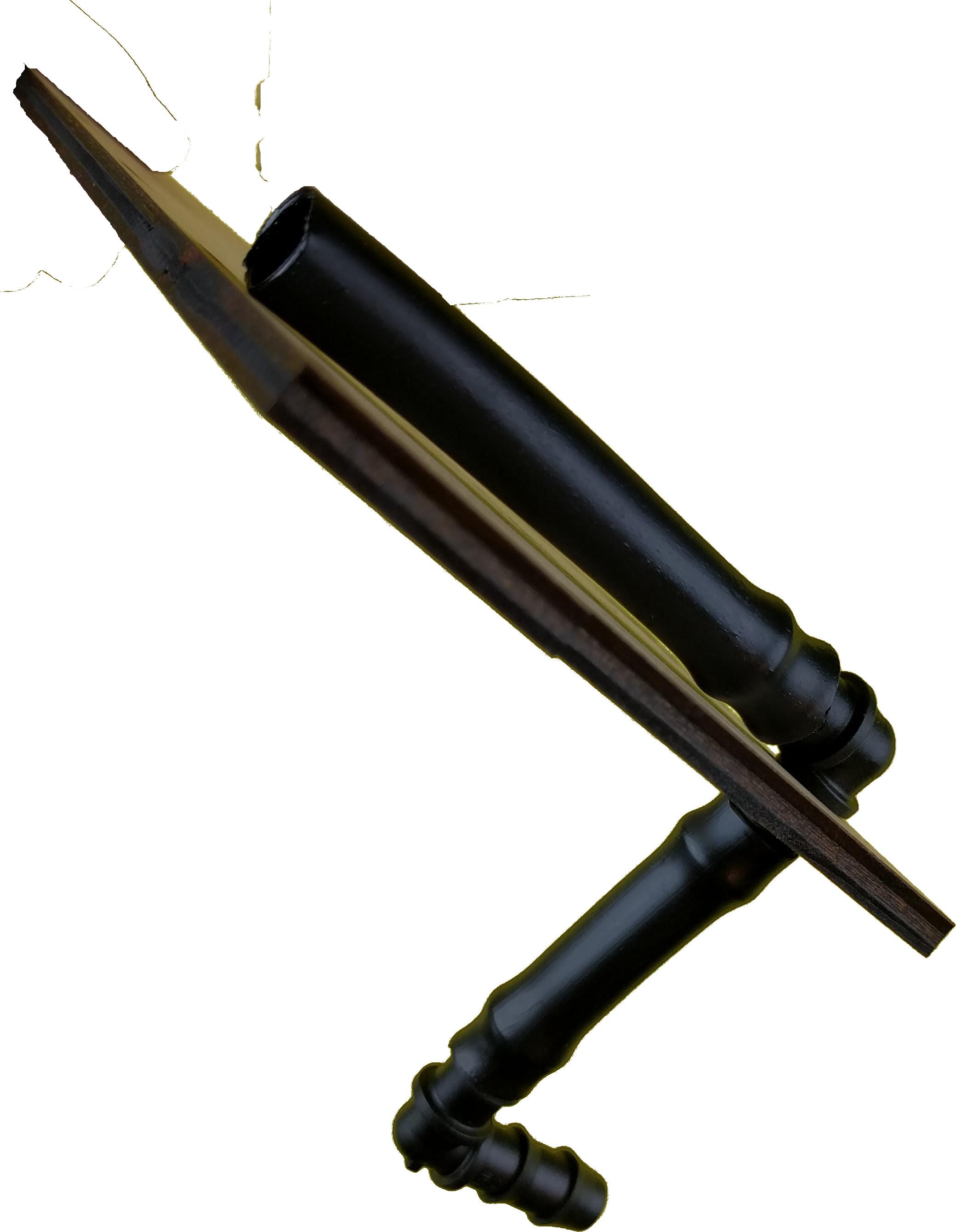
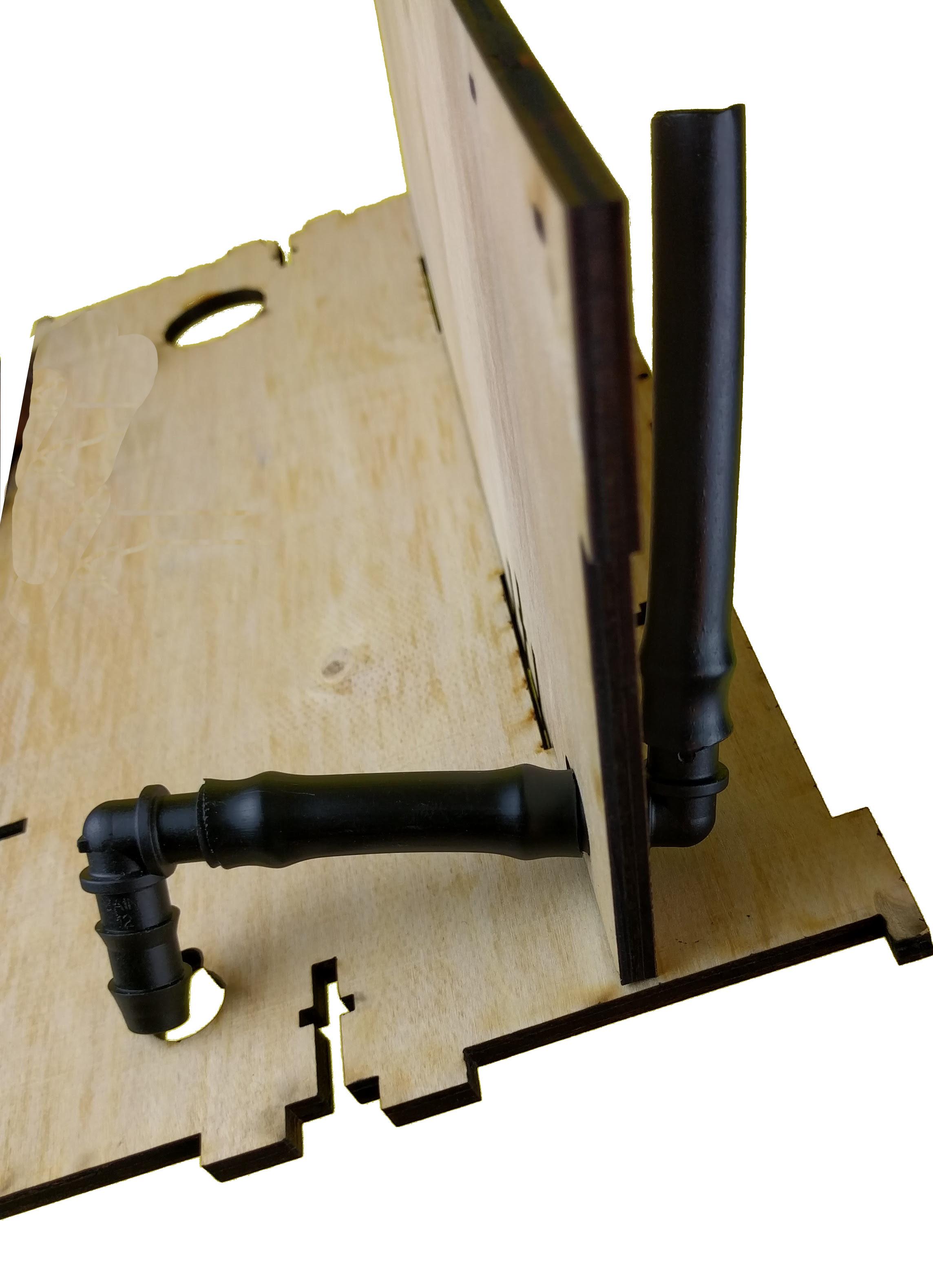
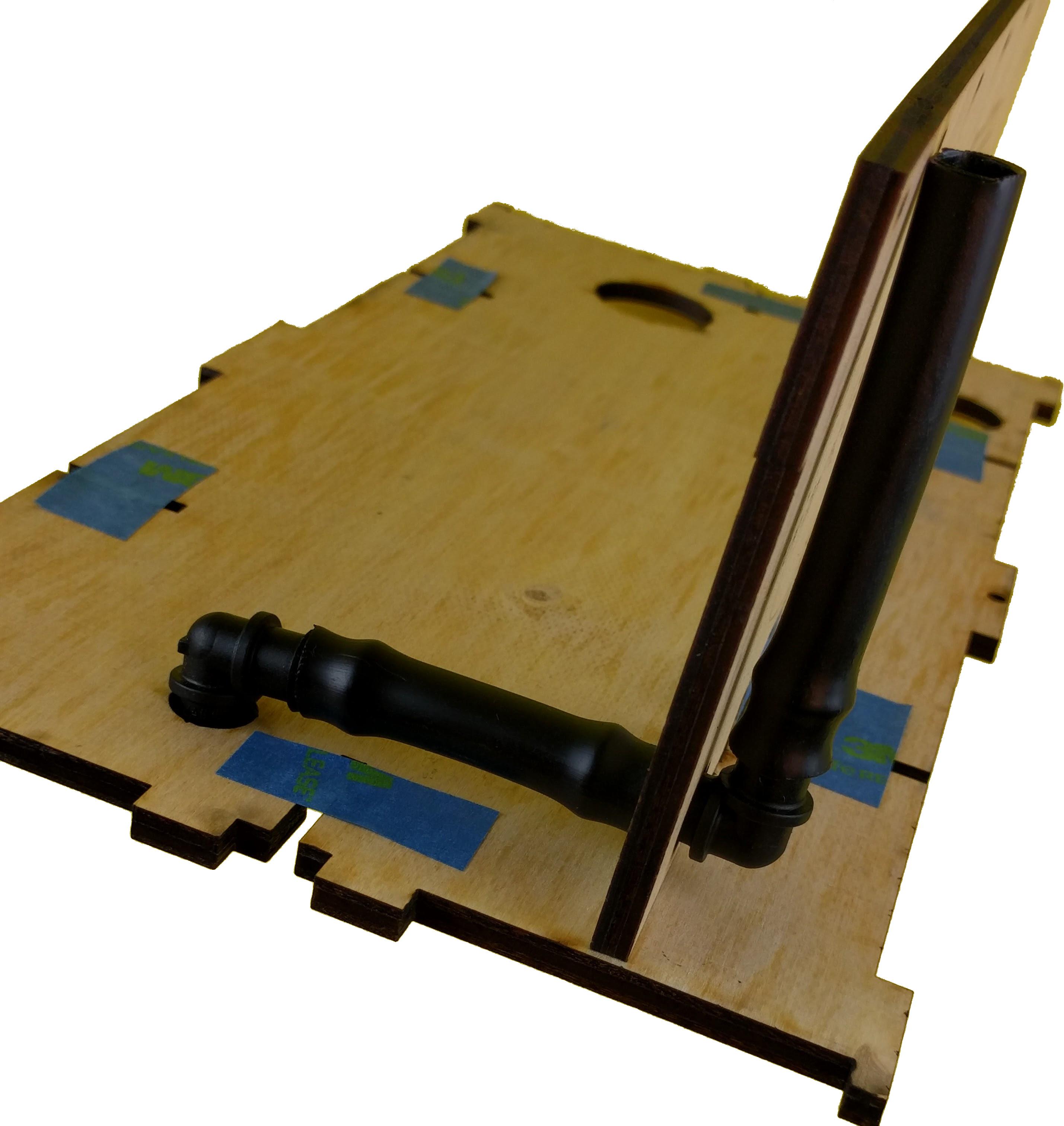
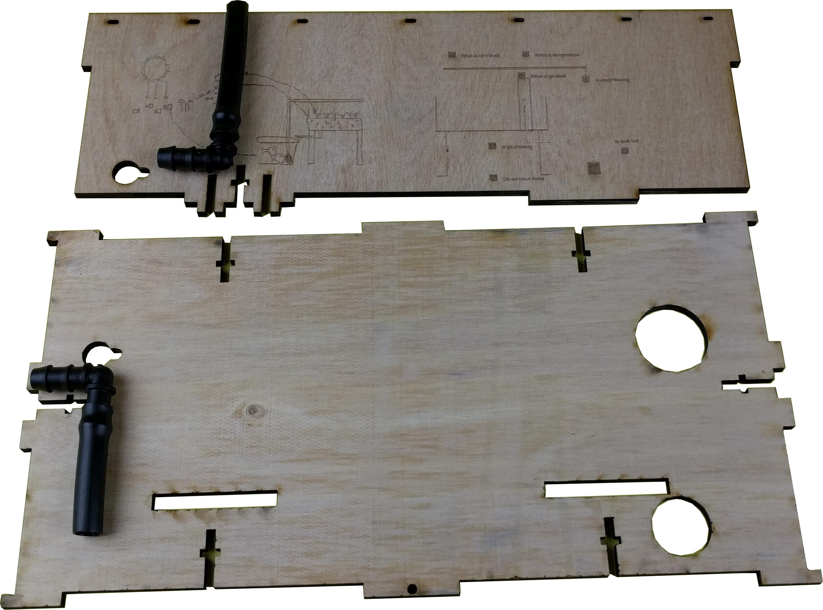
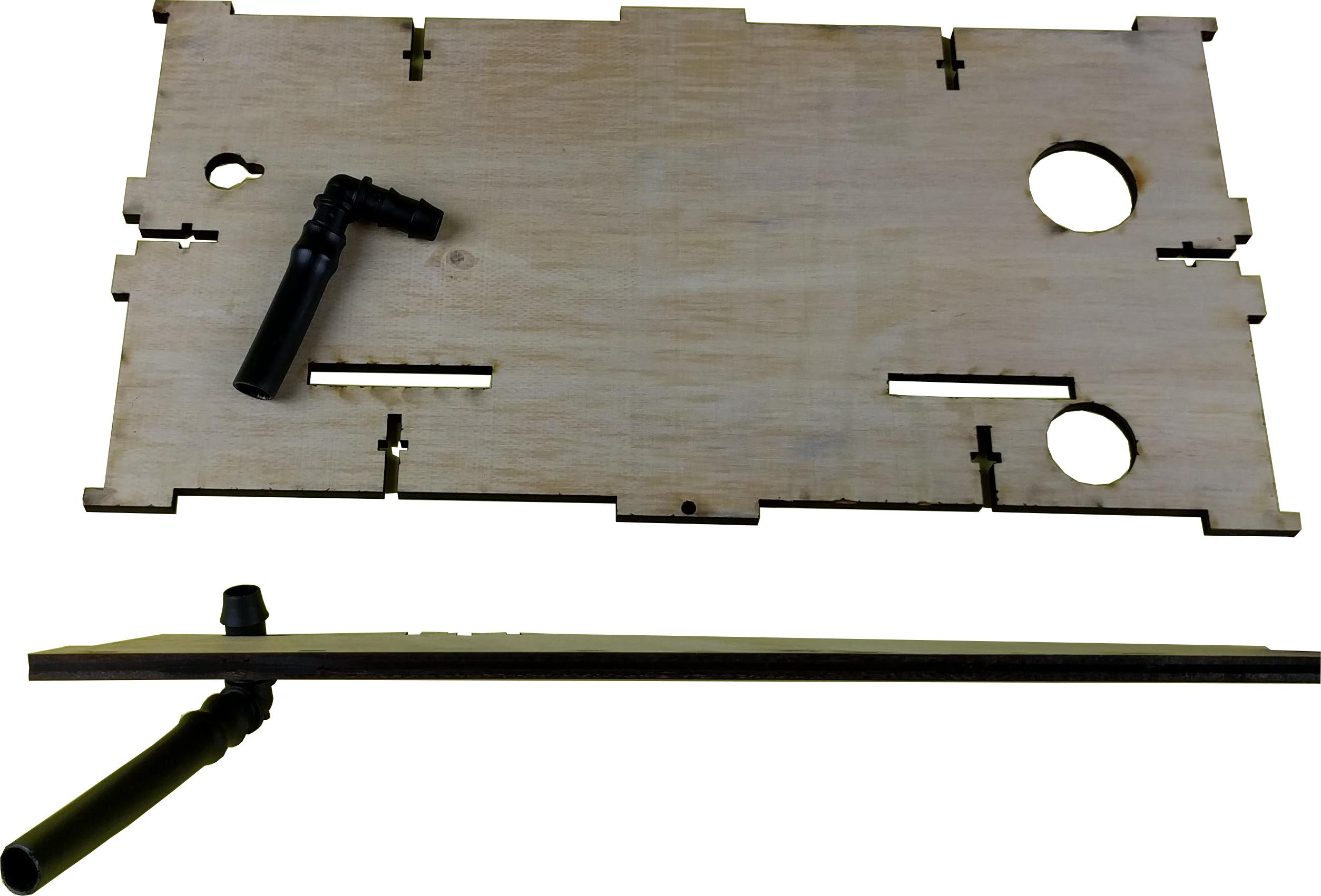
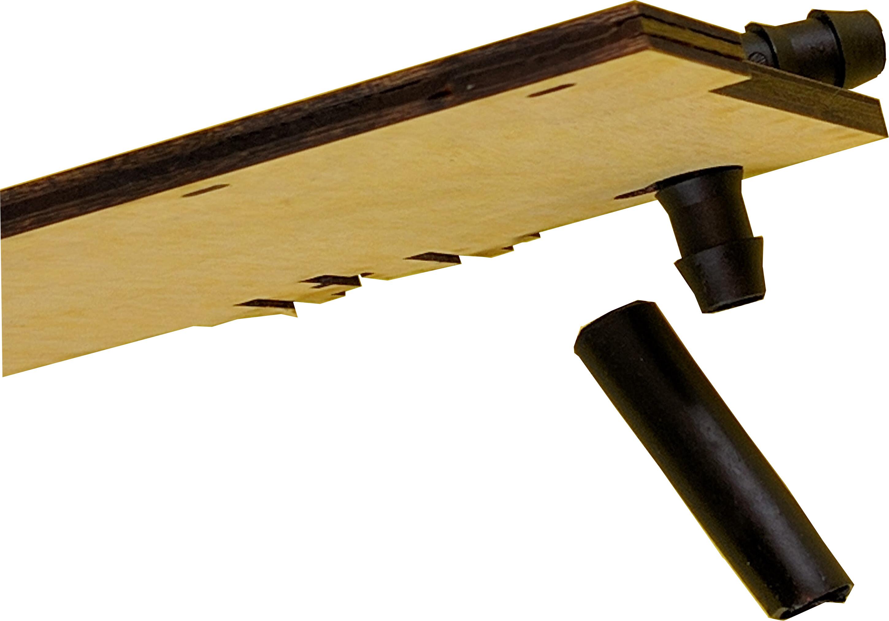
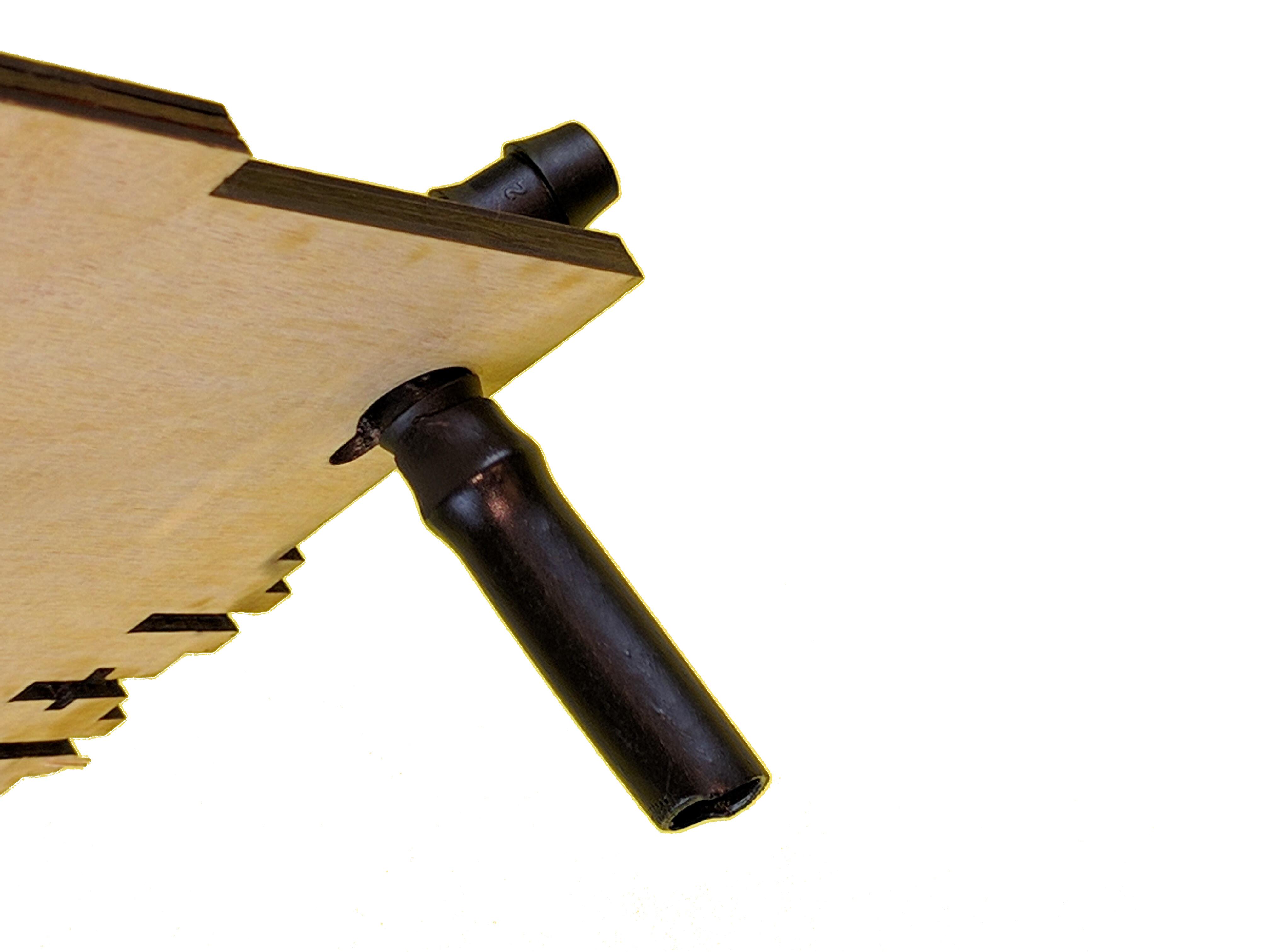
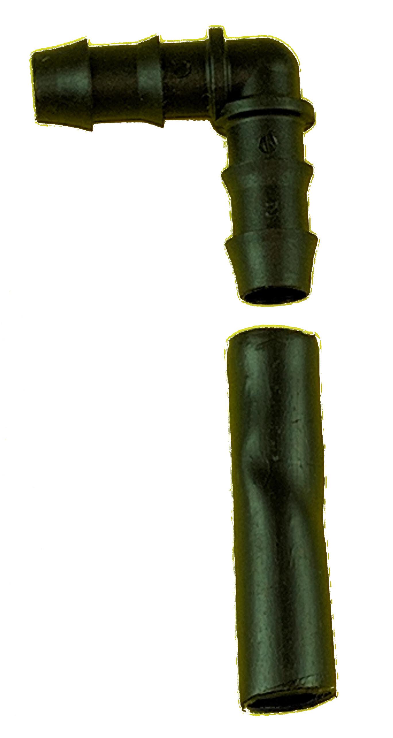
The irrigation tubing runs underneath the liner. But this step is shown without the liner for clarity. The tubing from the pump to the garden irrigation is connected as shown between the storyboard panel and the grow-bed. Simple plug and thread through the holes on the panels as shown
Adding the Water Pump
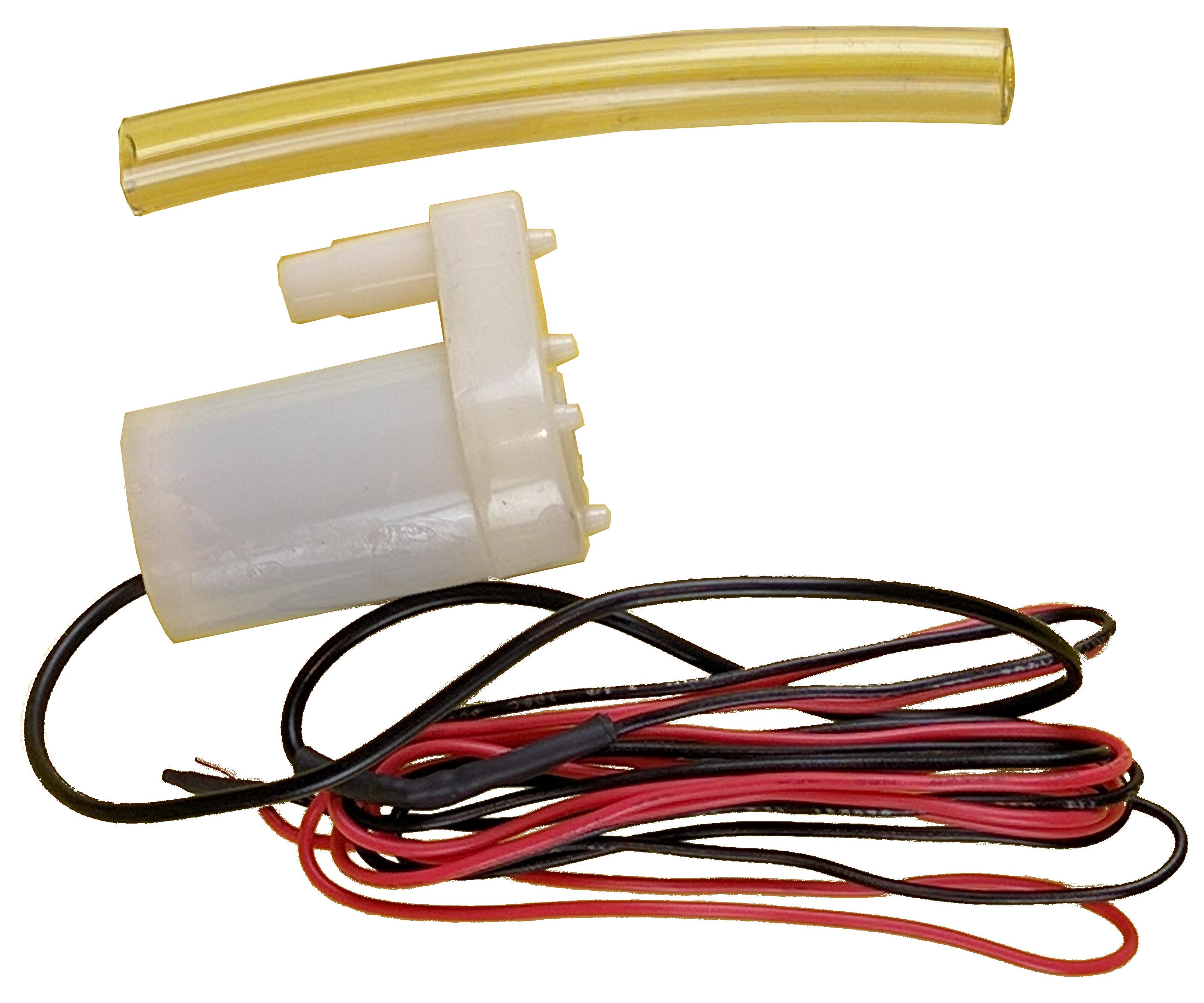
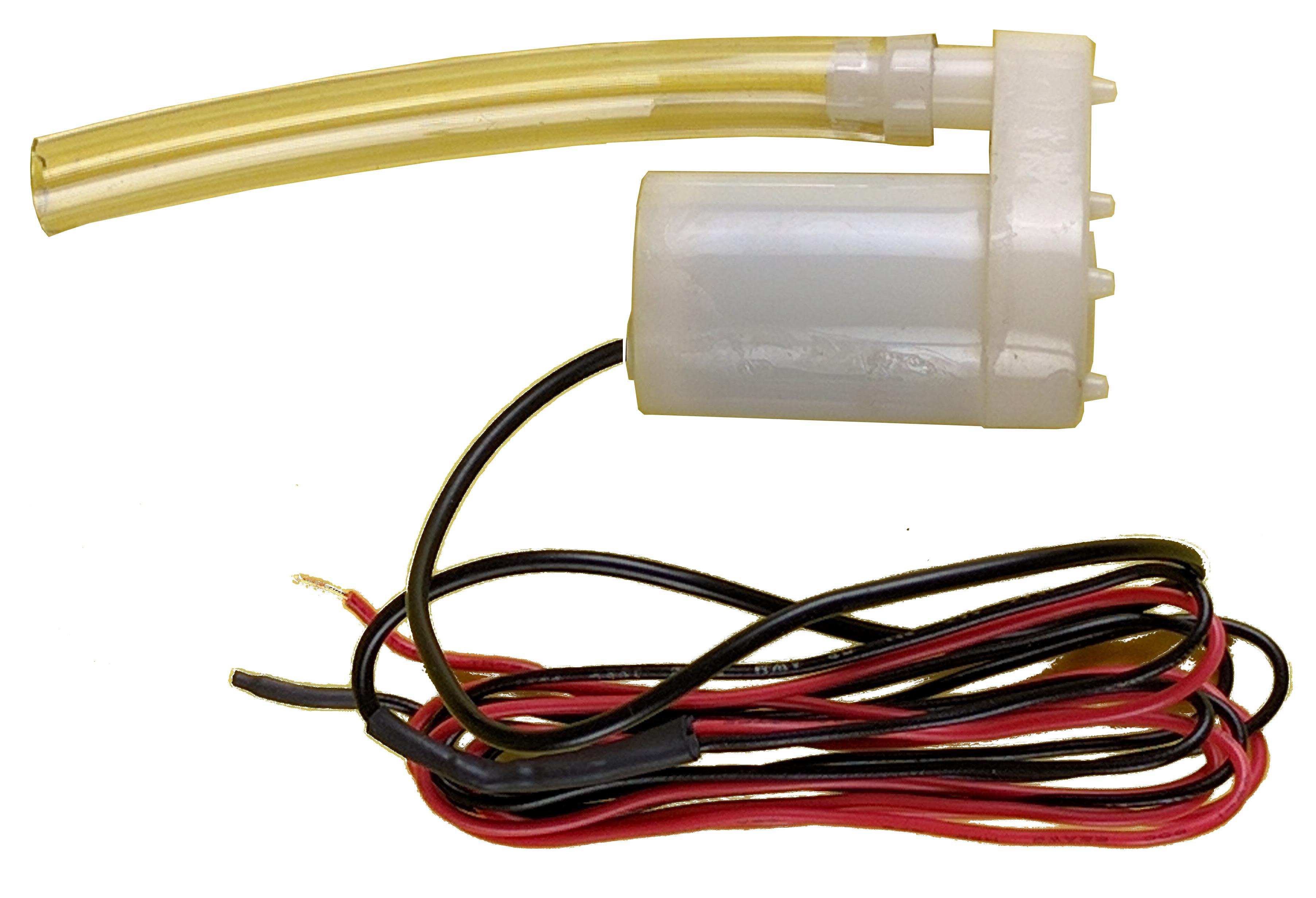
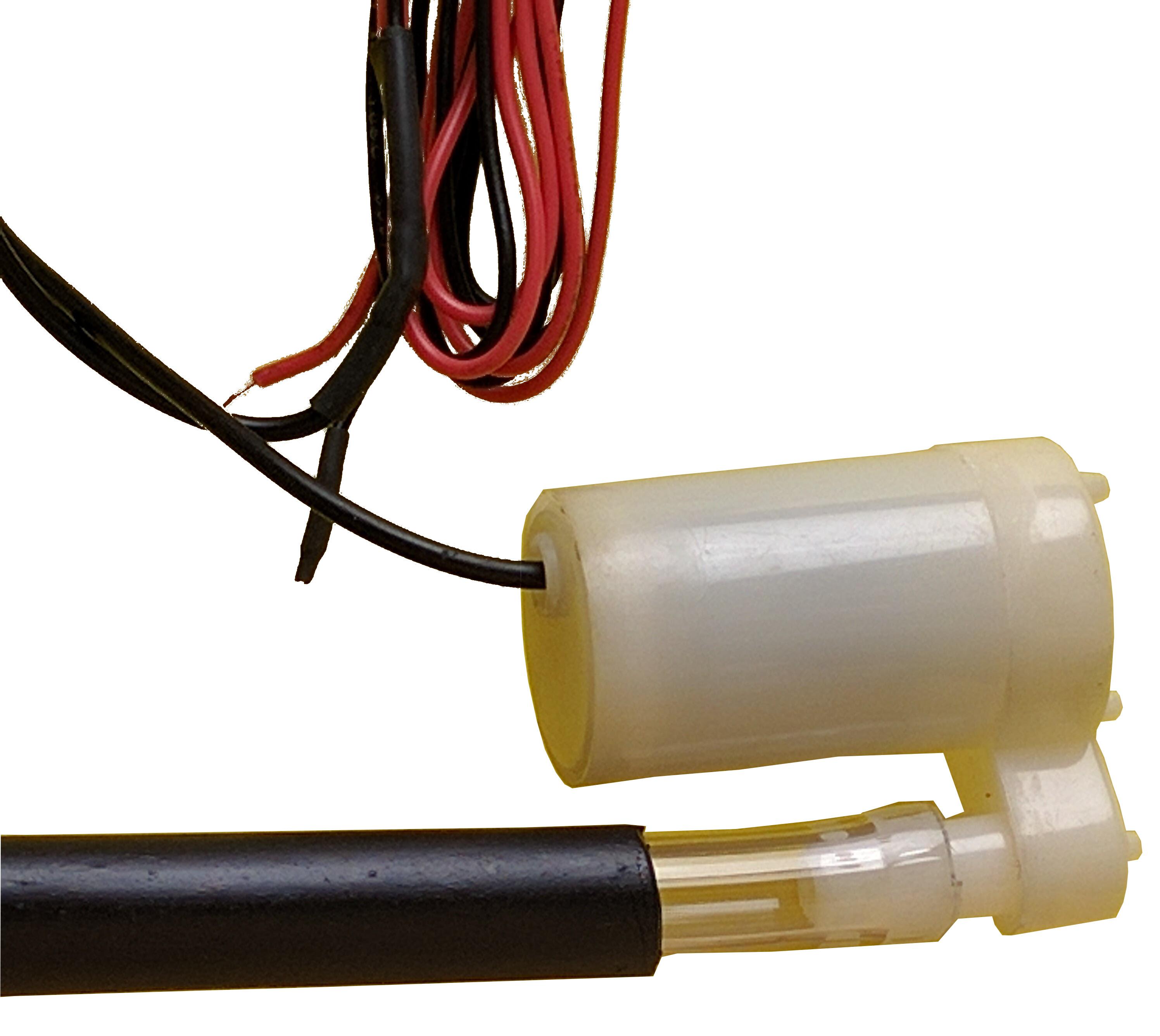
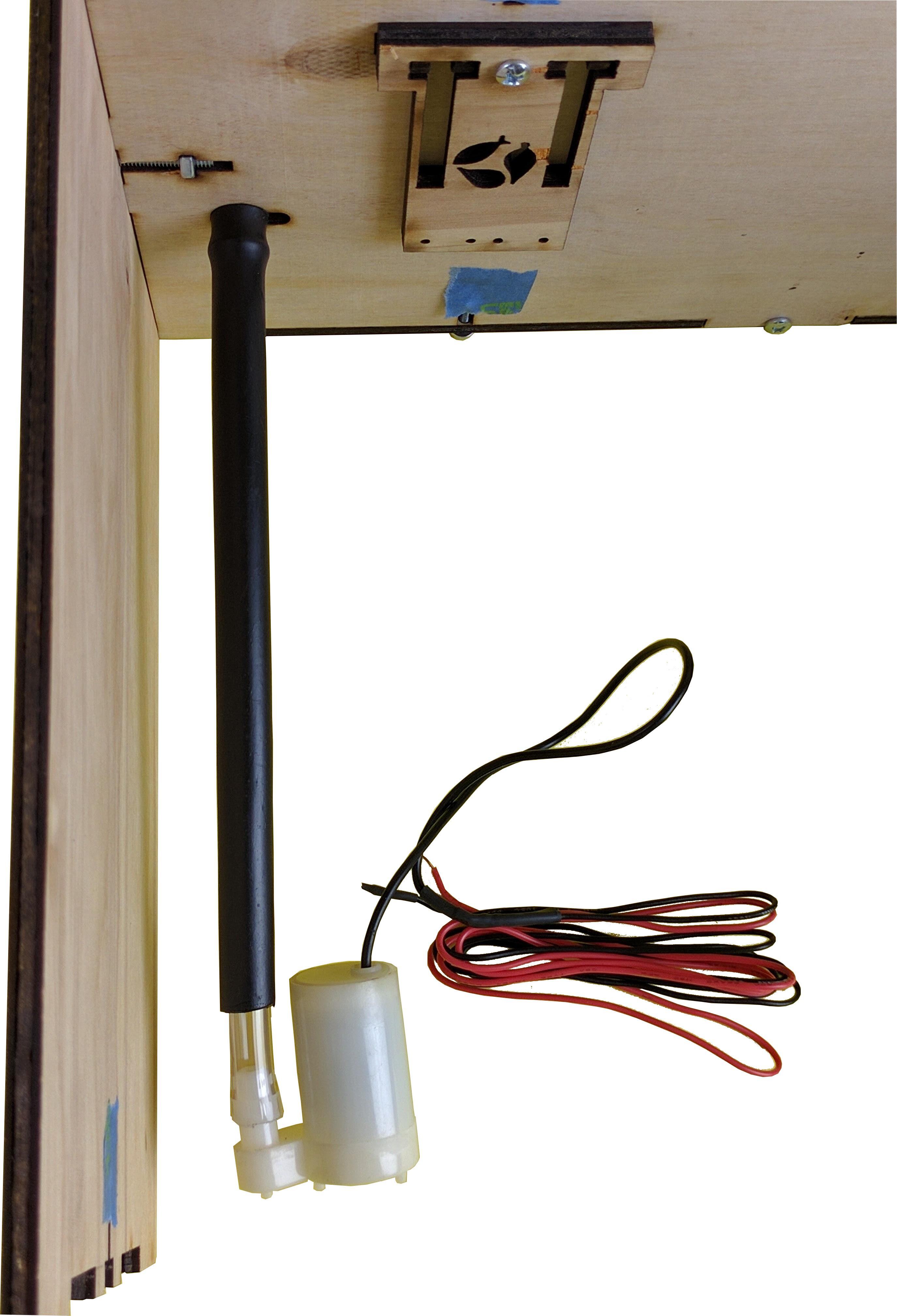
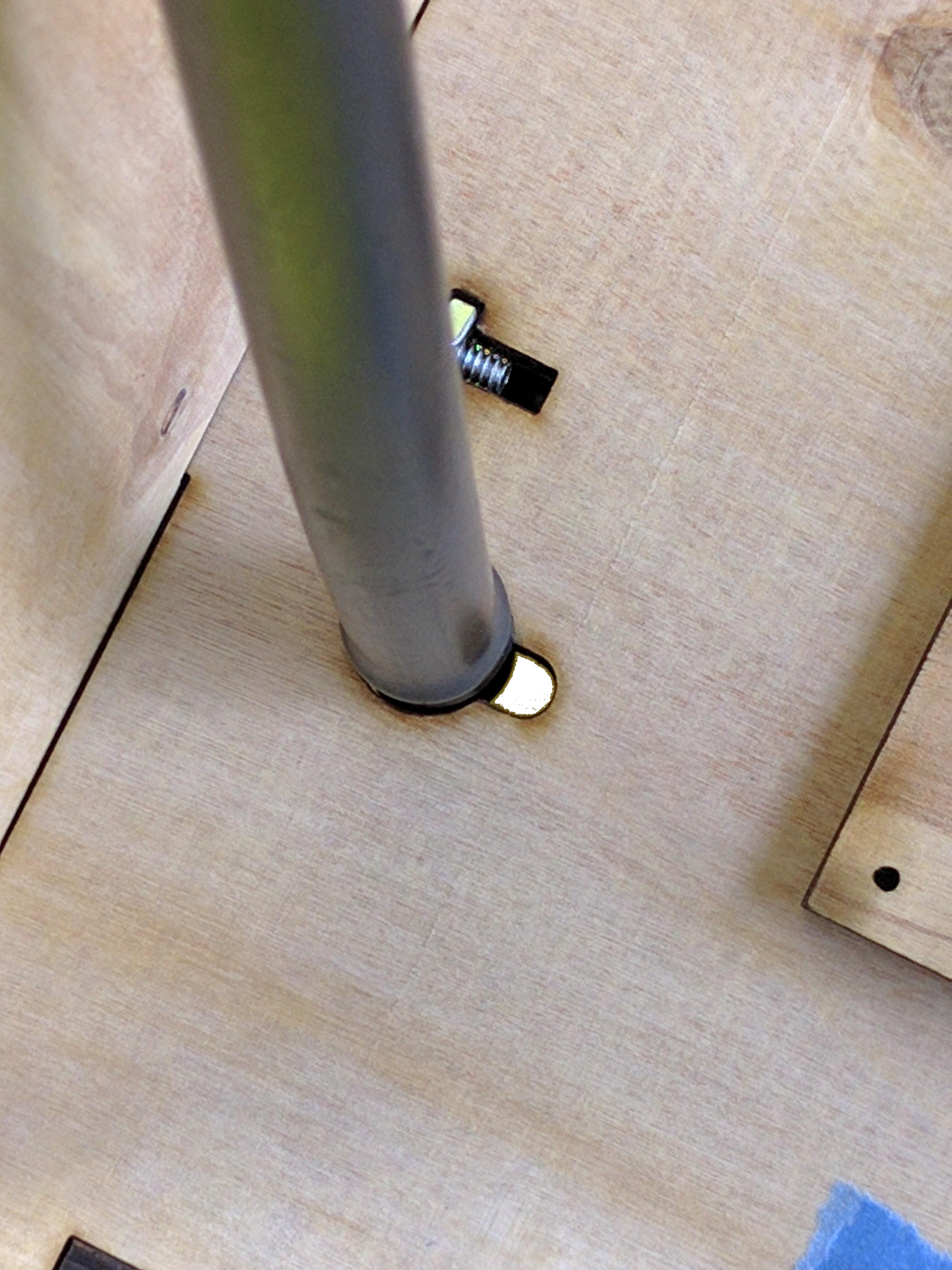
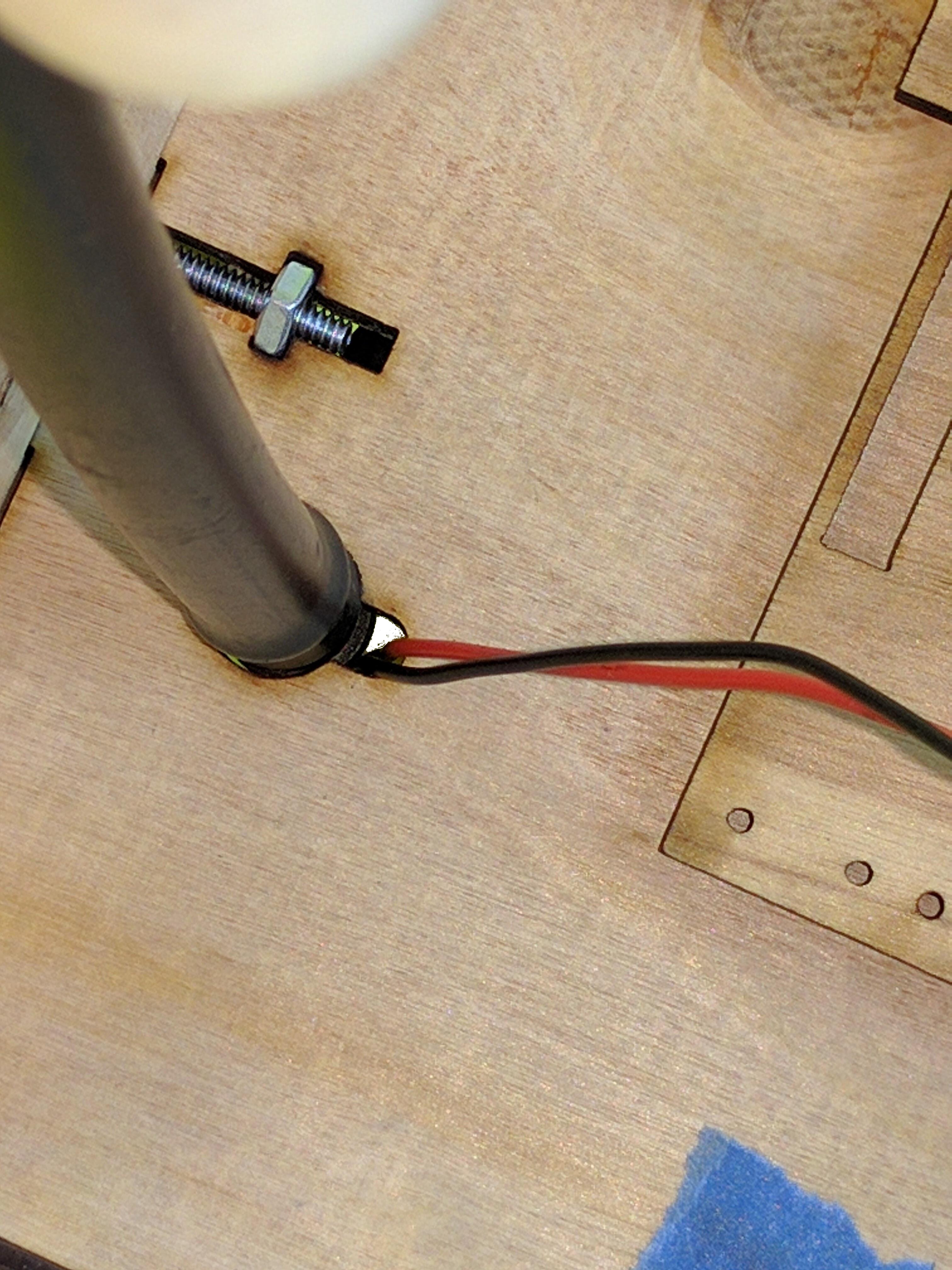
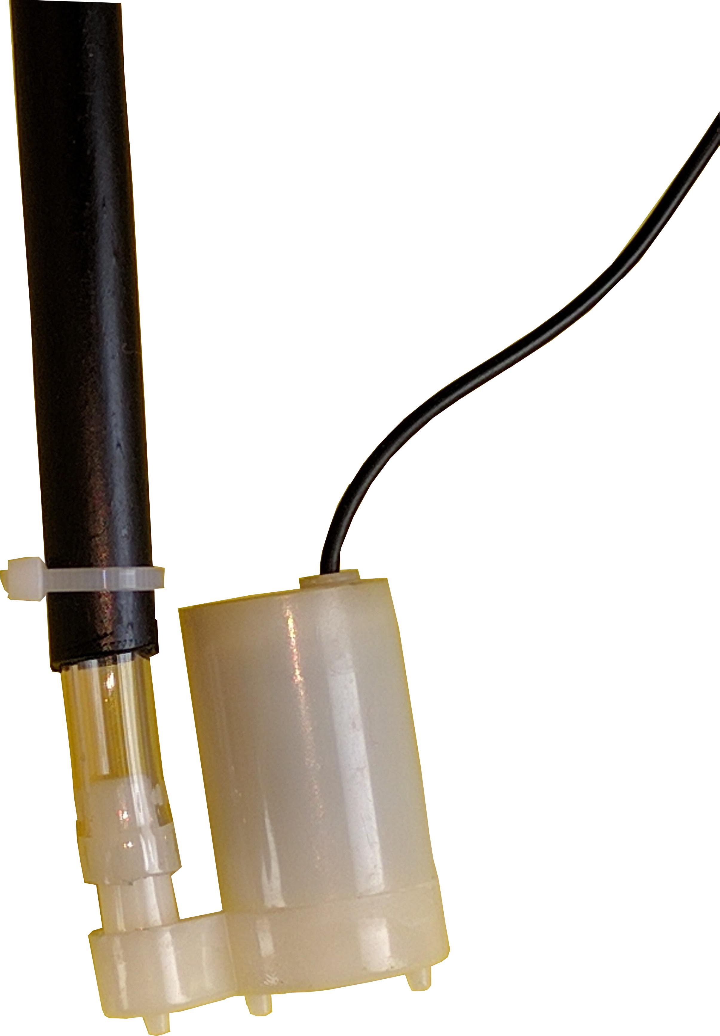
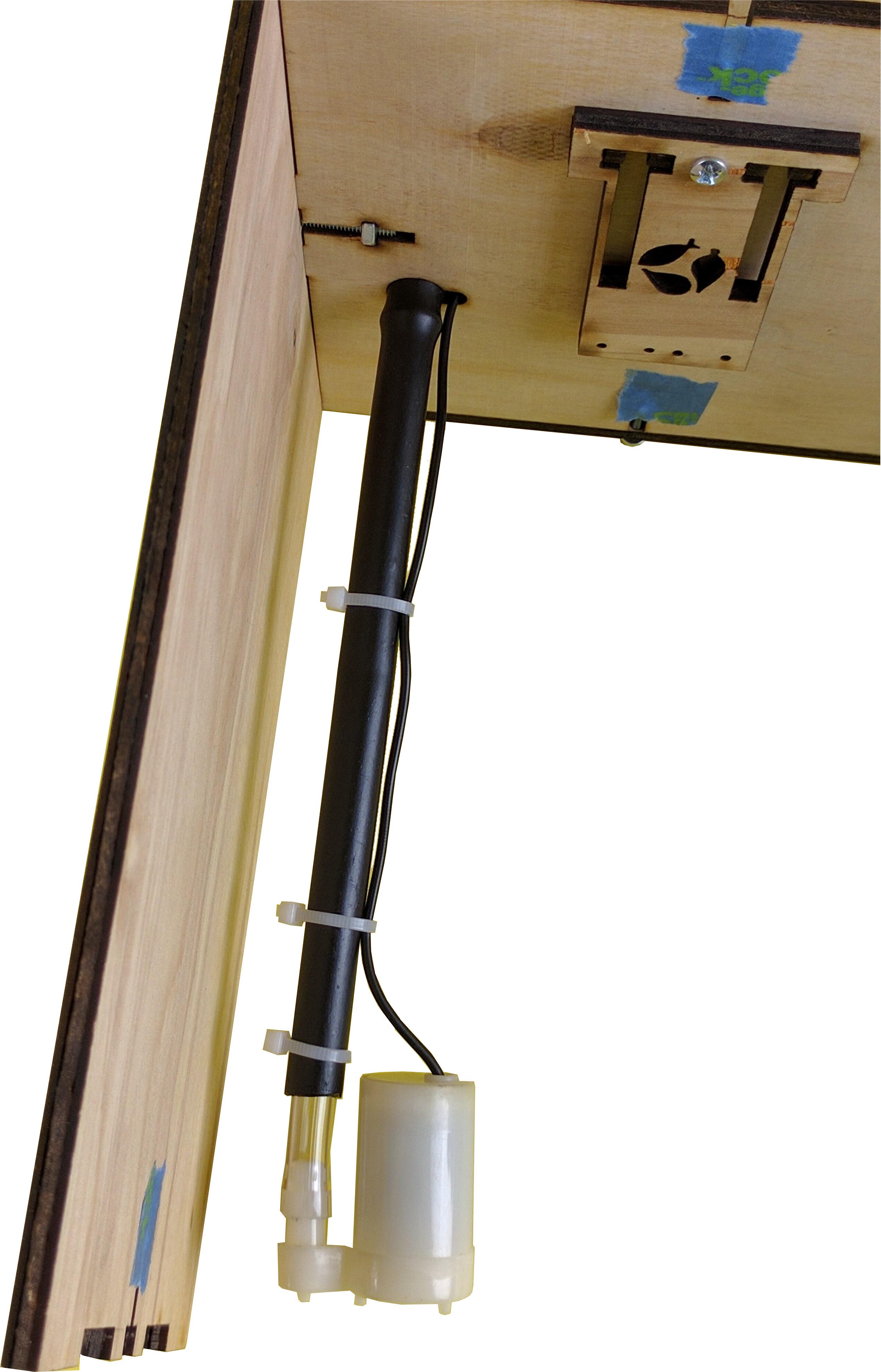
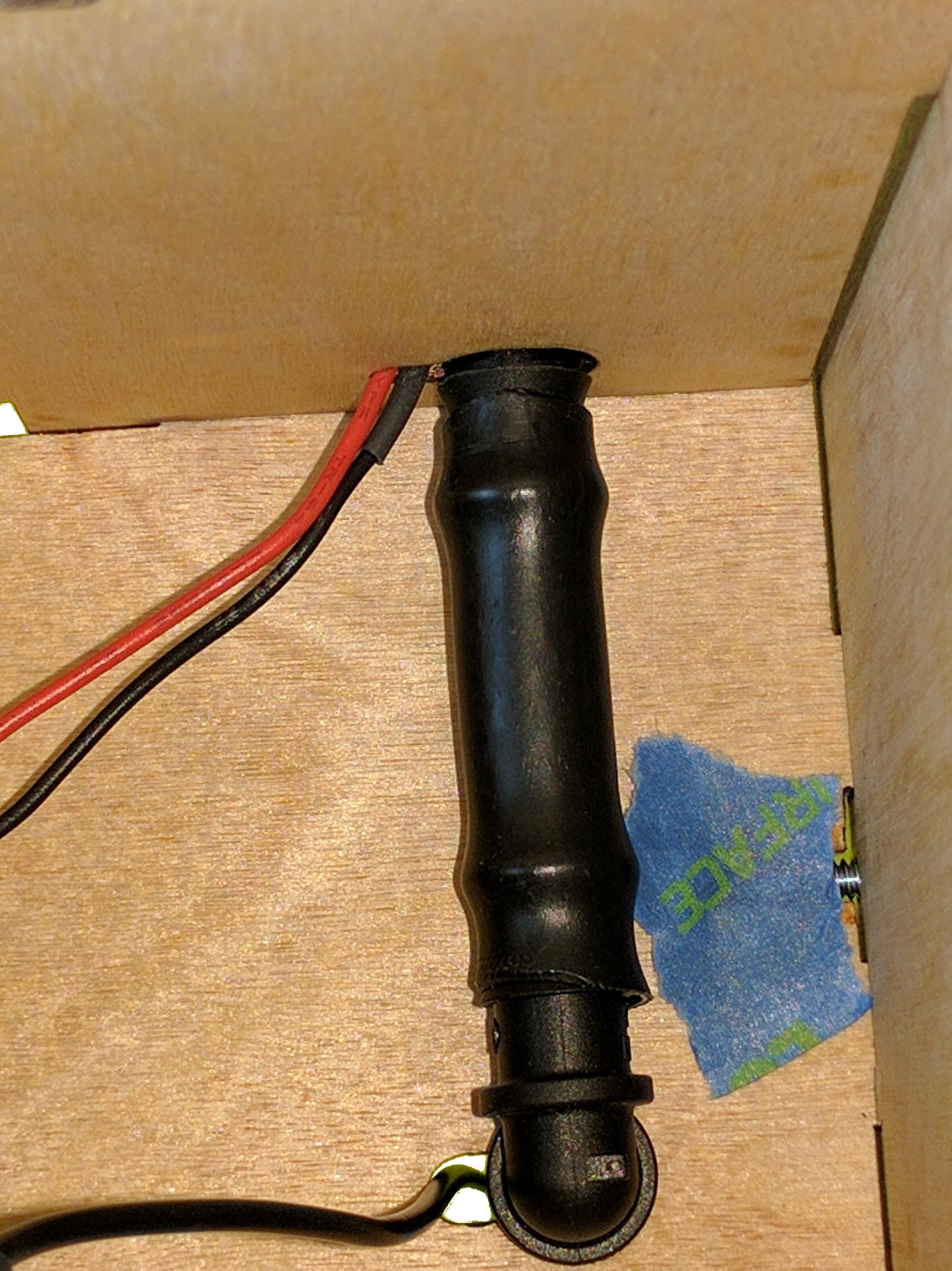
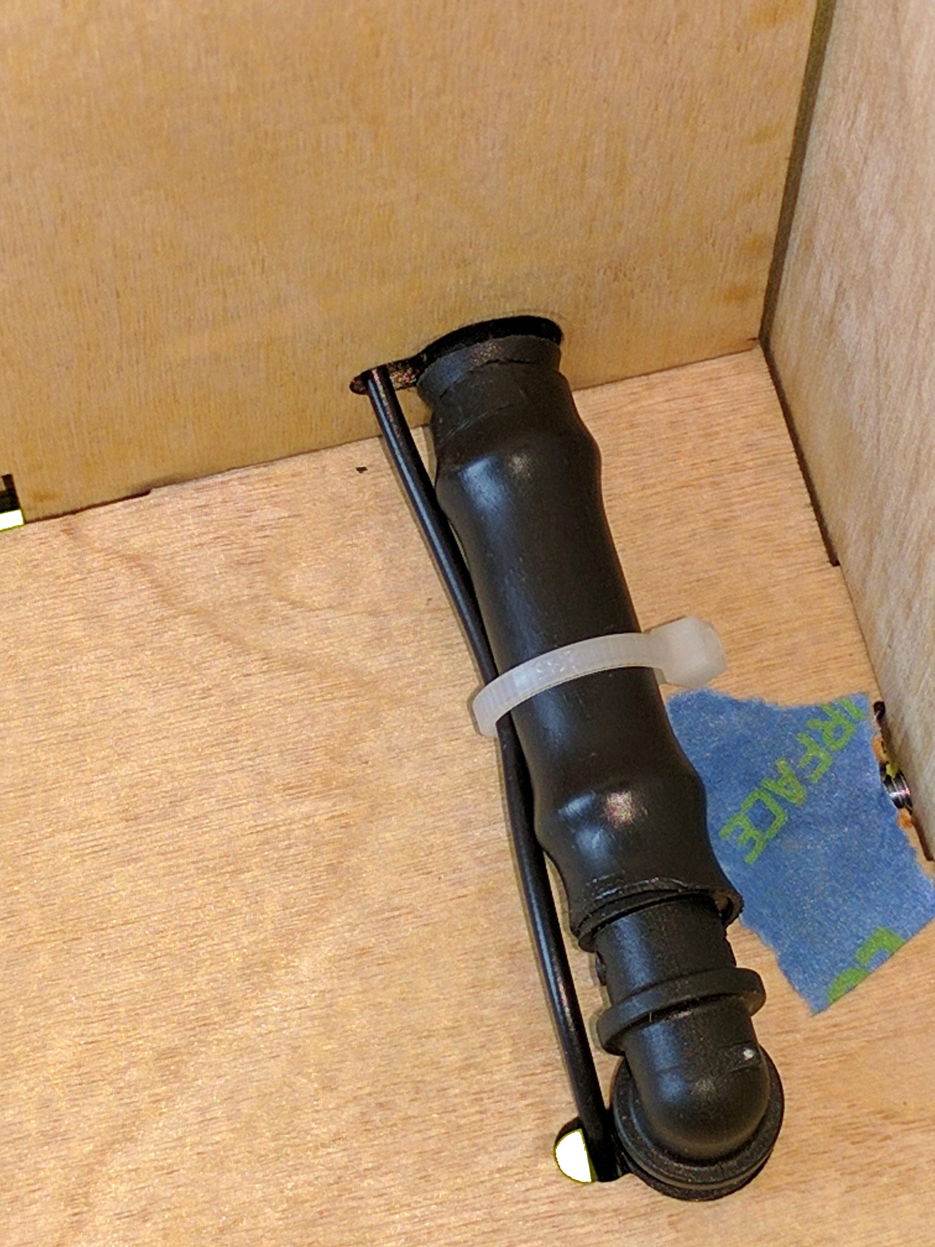
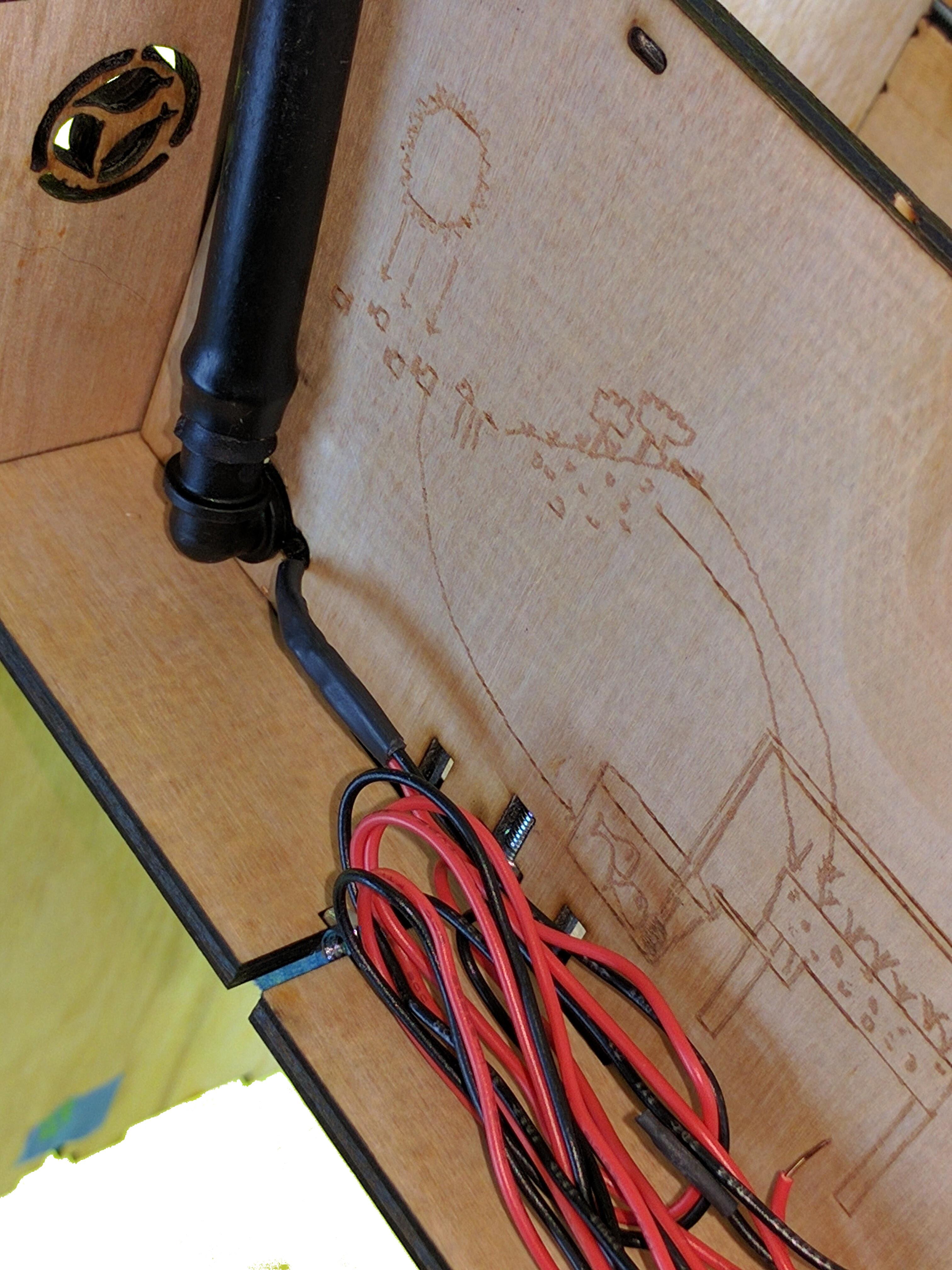

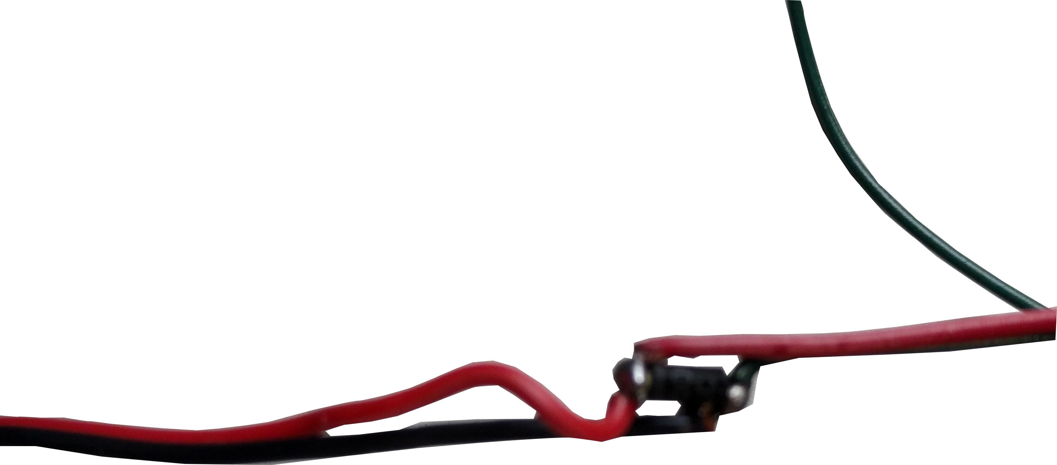
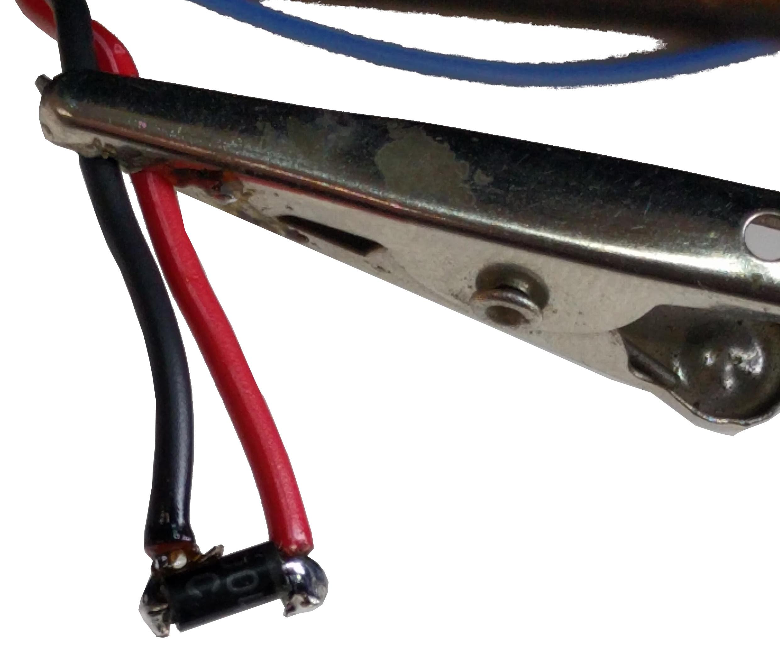
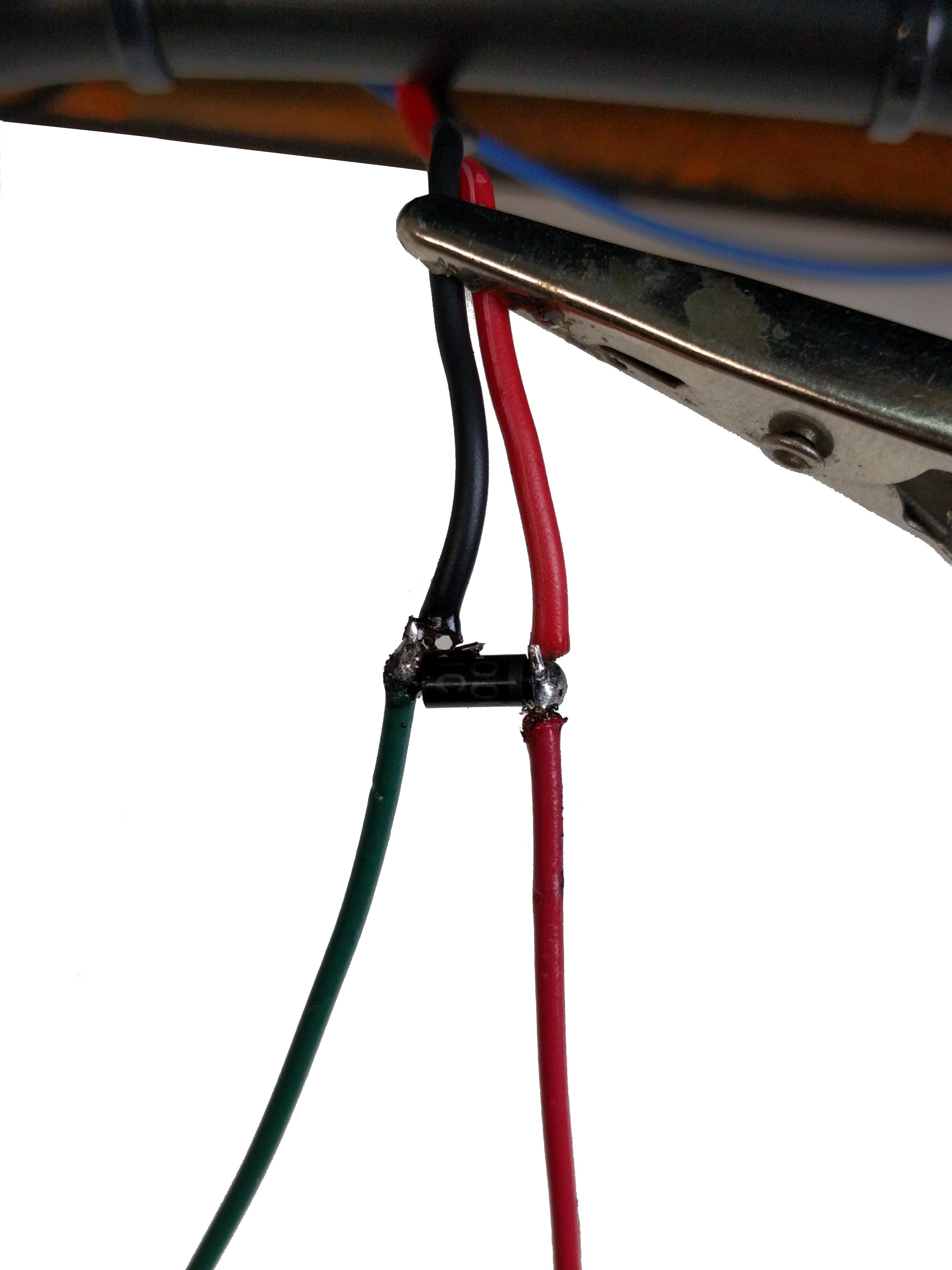
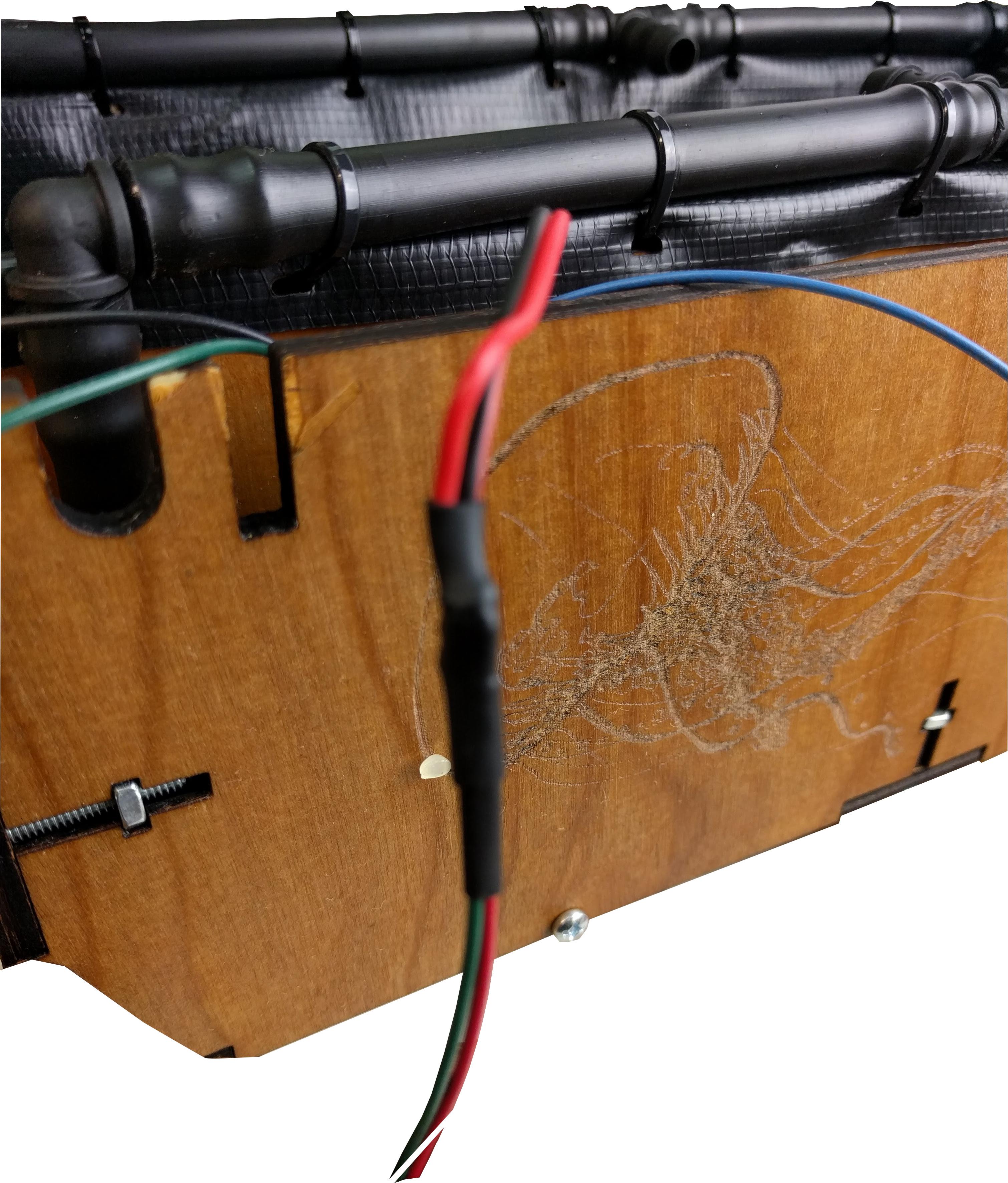
The pump sits inside the fish tank at the beginning of the irrigation tubing. I had to use a smaller tube to interface the two. The wiring will run underneath the liner(not shown here for clarity) and along with the irrigation tubing. Zip everything together for a clean finish. The pump being an electromagnetic device will require a flywheel diode to protect the electronics from back emf. This is also shown
Overflow Sensor

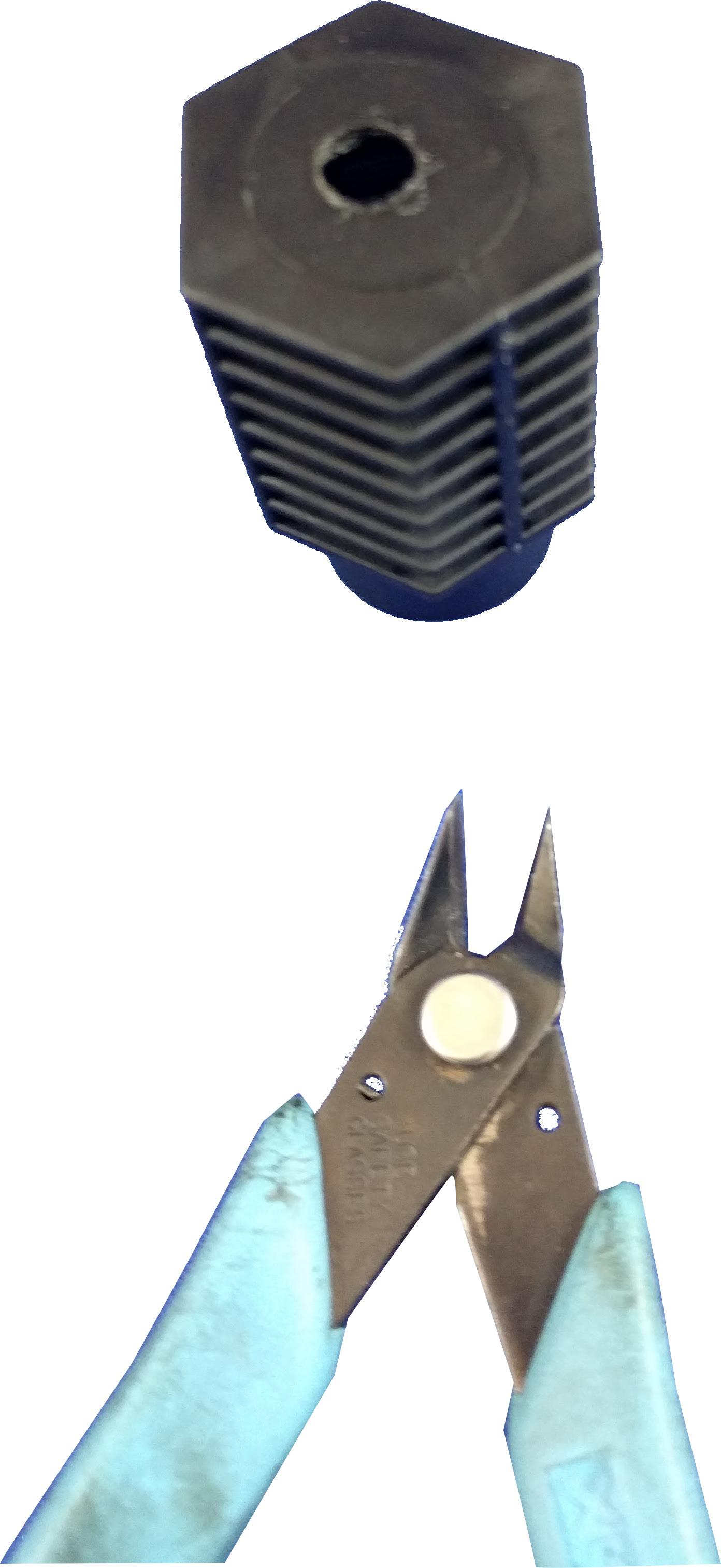
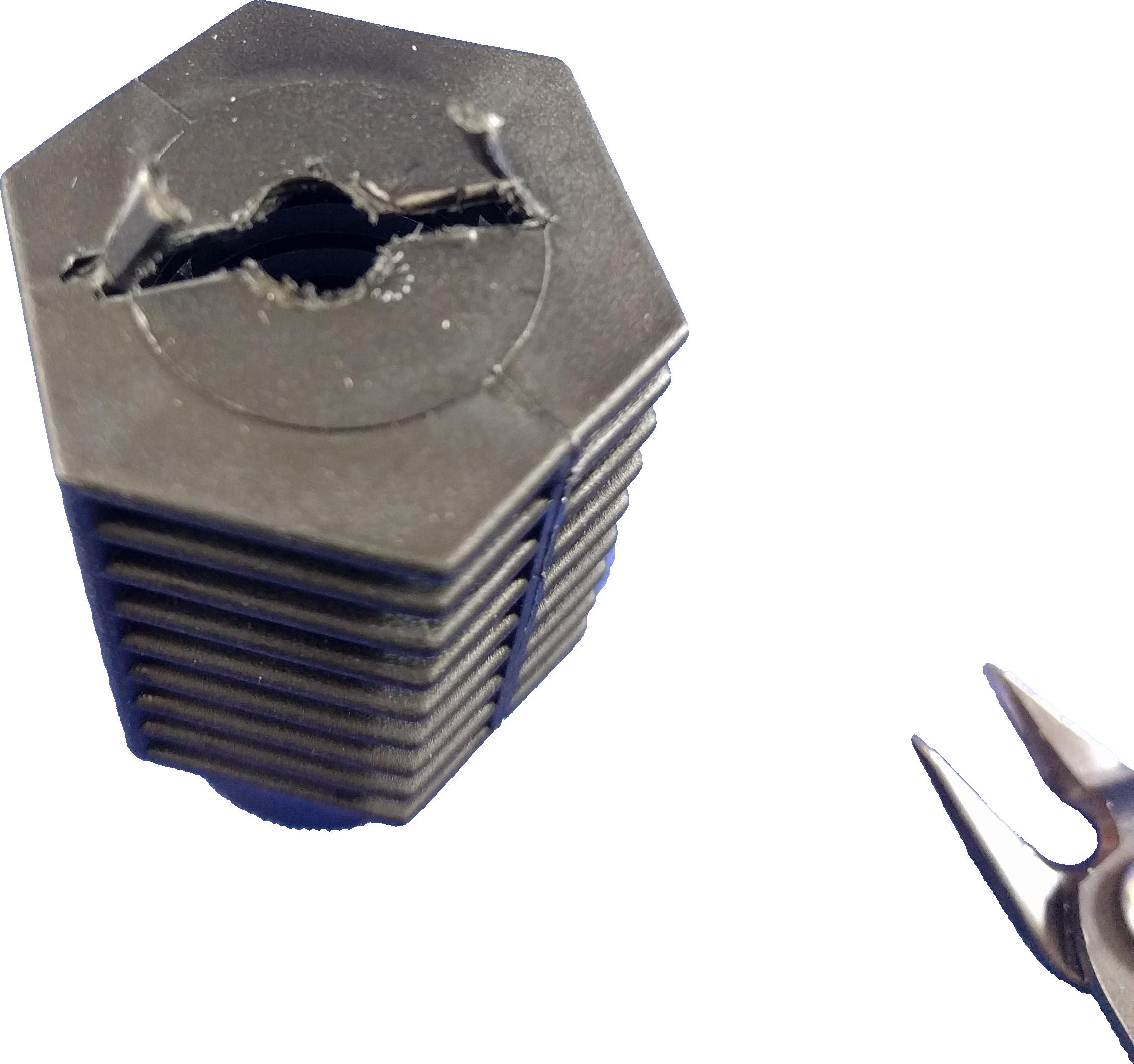
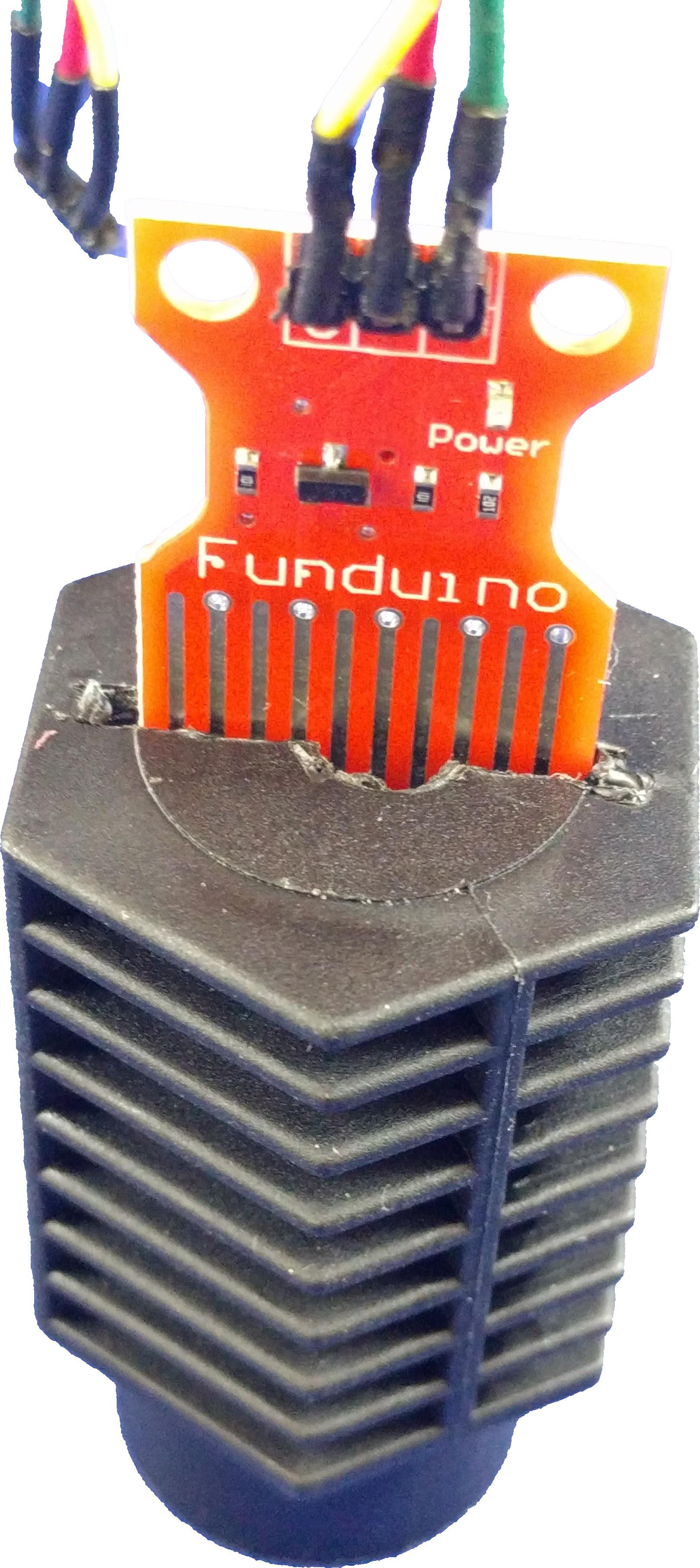
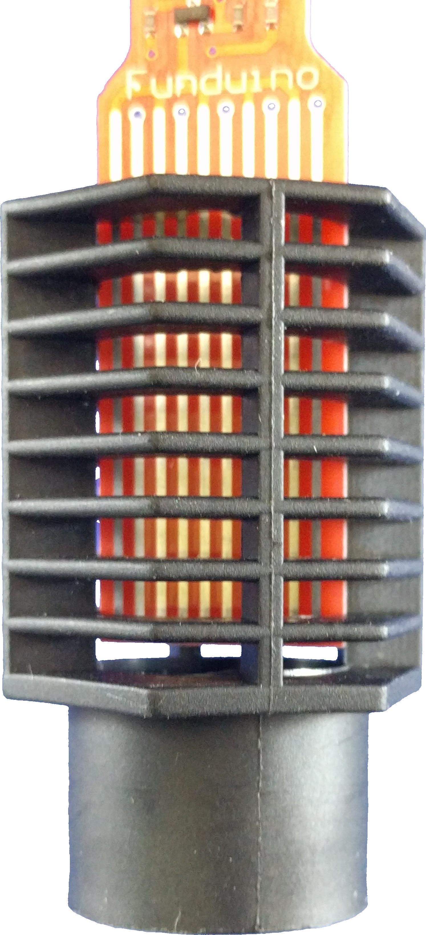
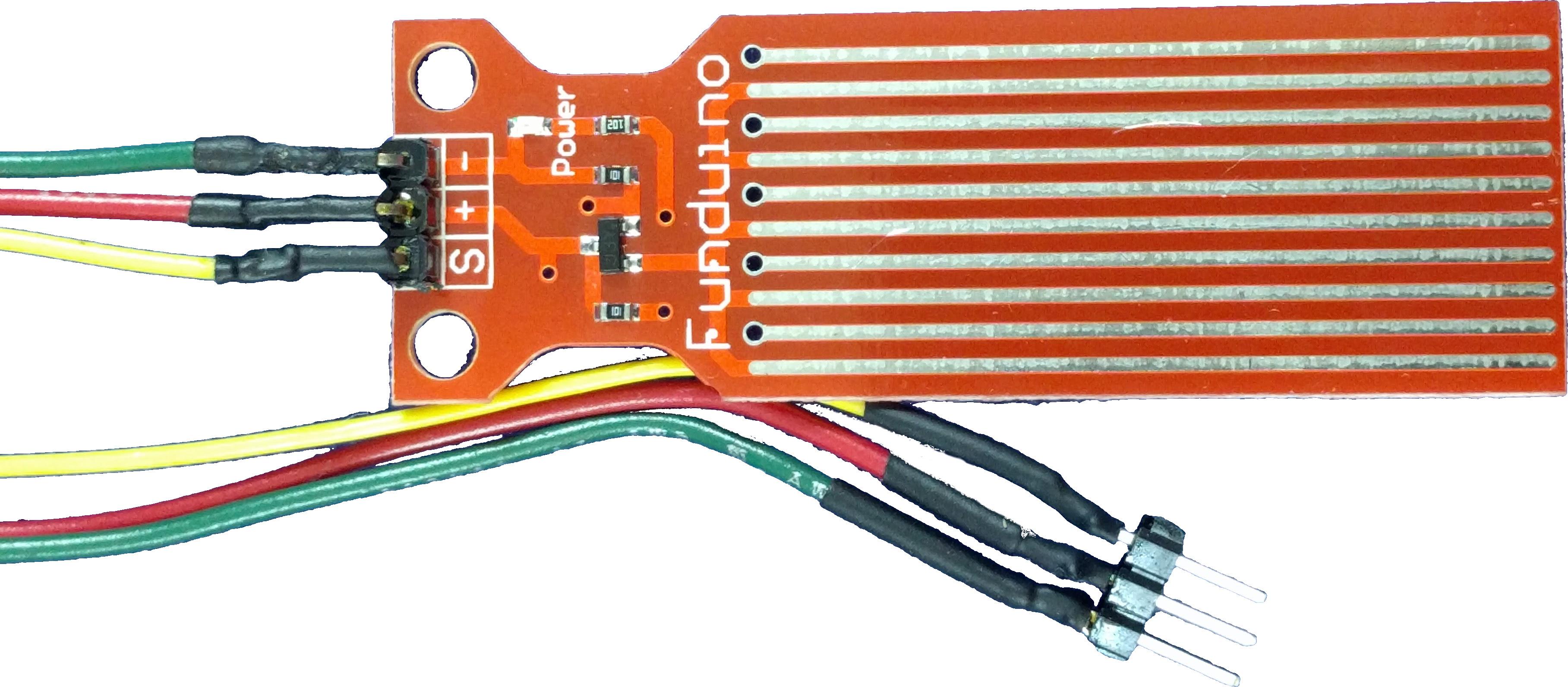
As the plants grow, so will the roots, which can lead to blockages causing water to overflow on the garden. To prevent water leakage when this happens, a feedback look is employed using a water leak sensor on the drainage stand pipe. The pump is slowed when an overflow is detected.
Adding the Drainage
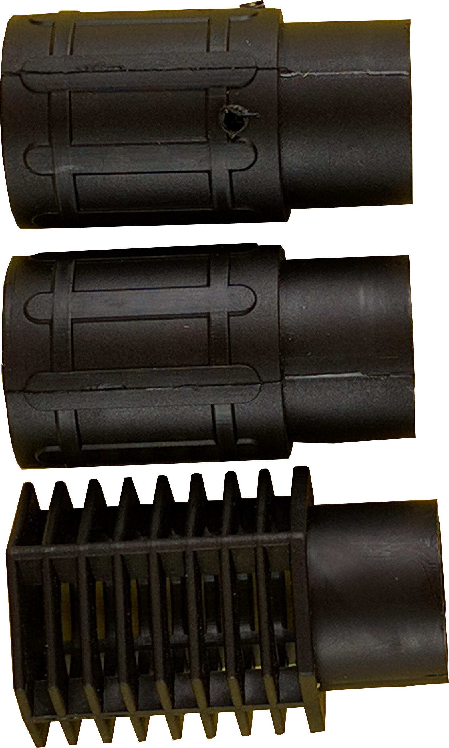
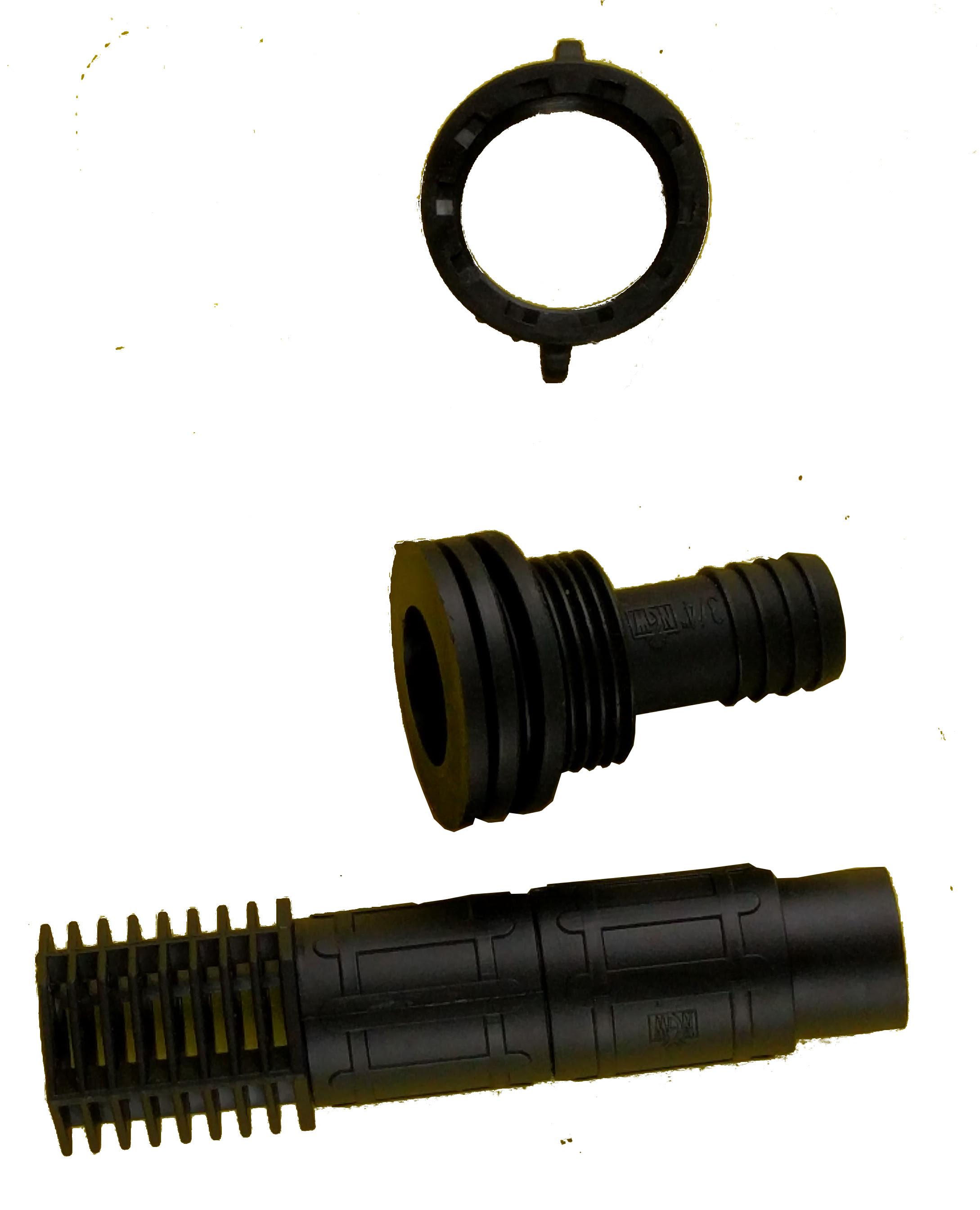
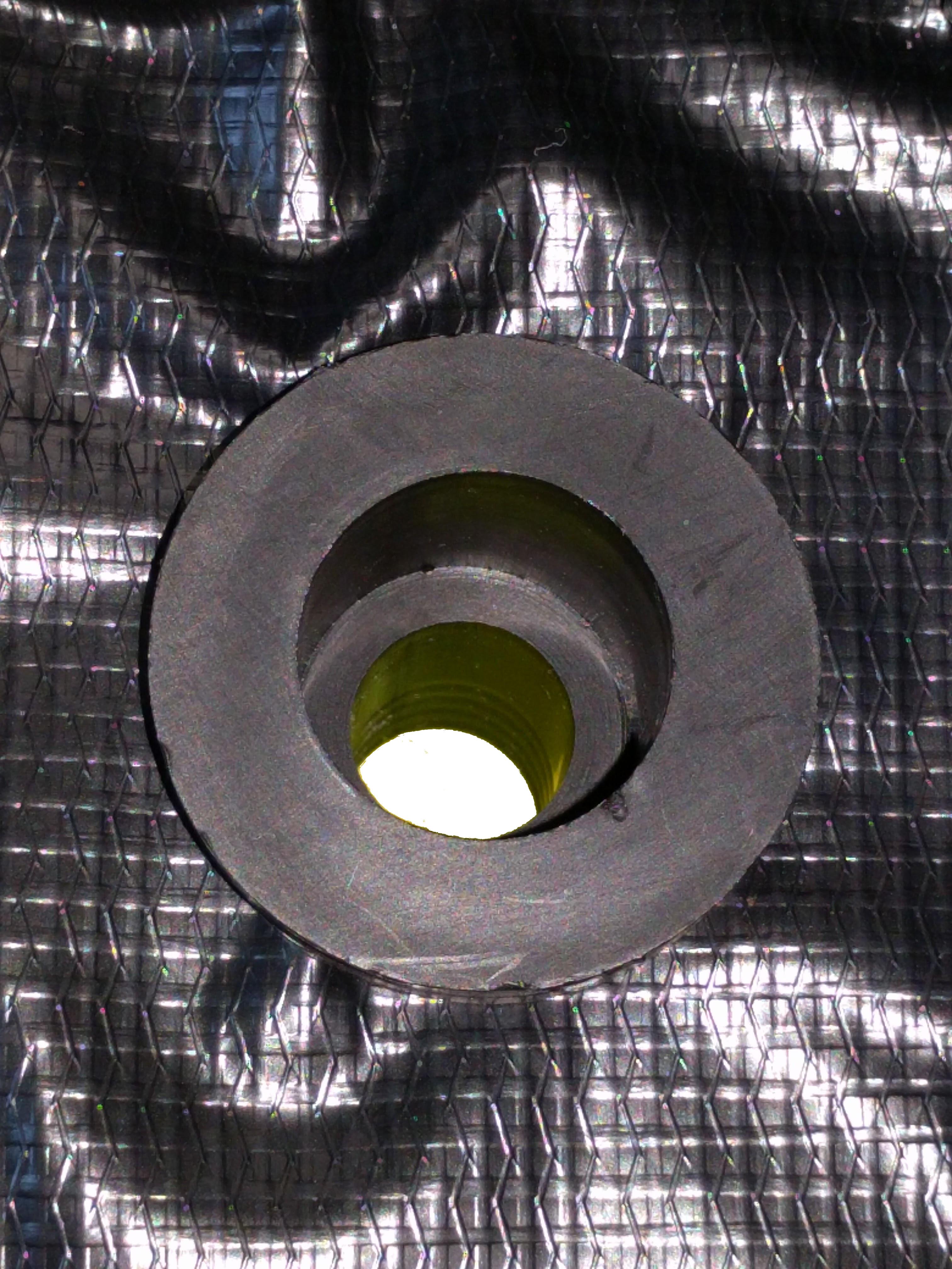
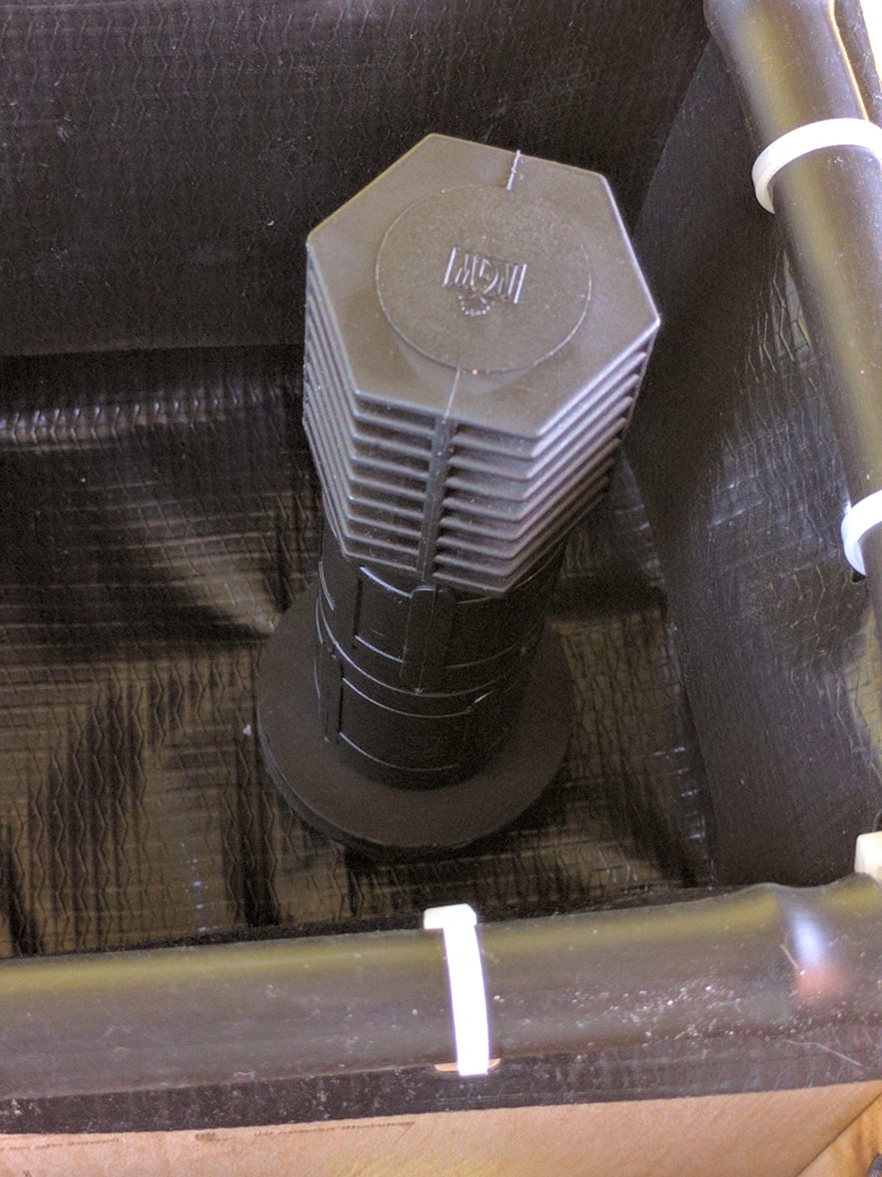
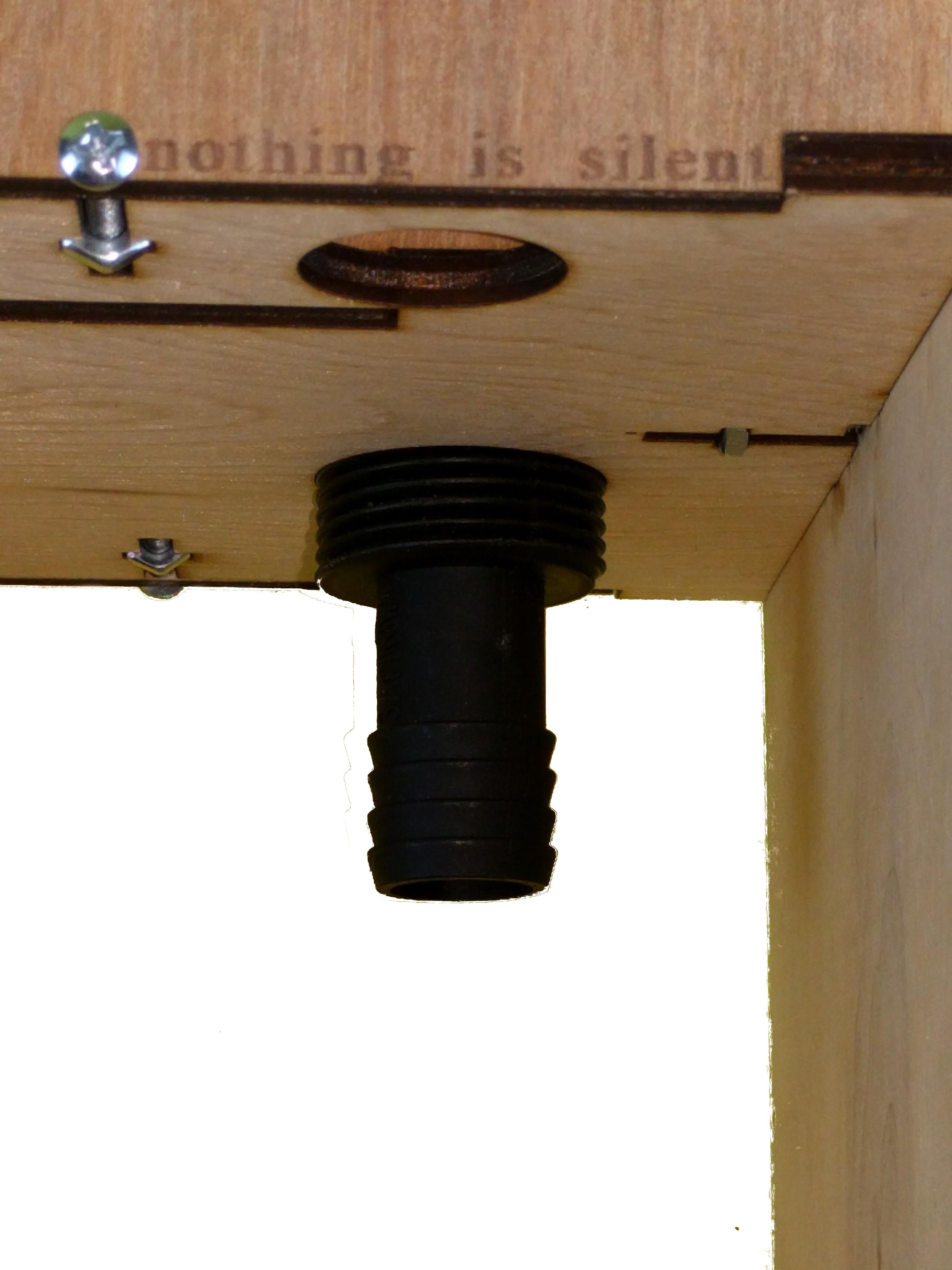
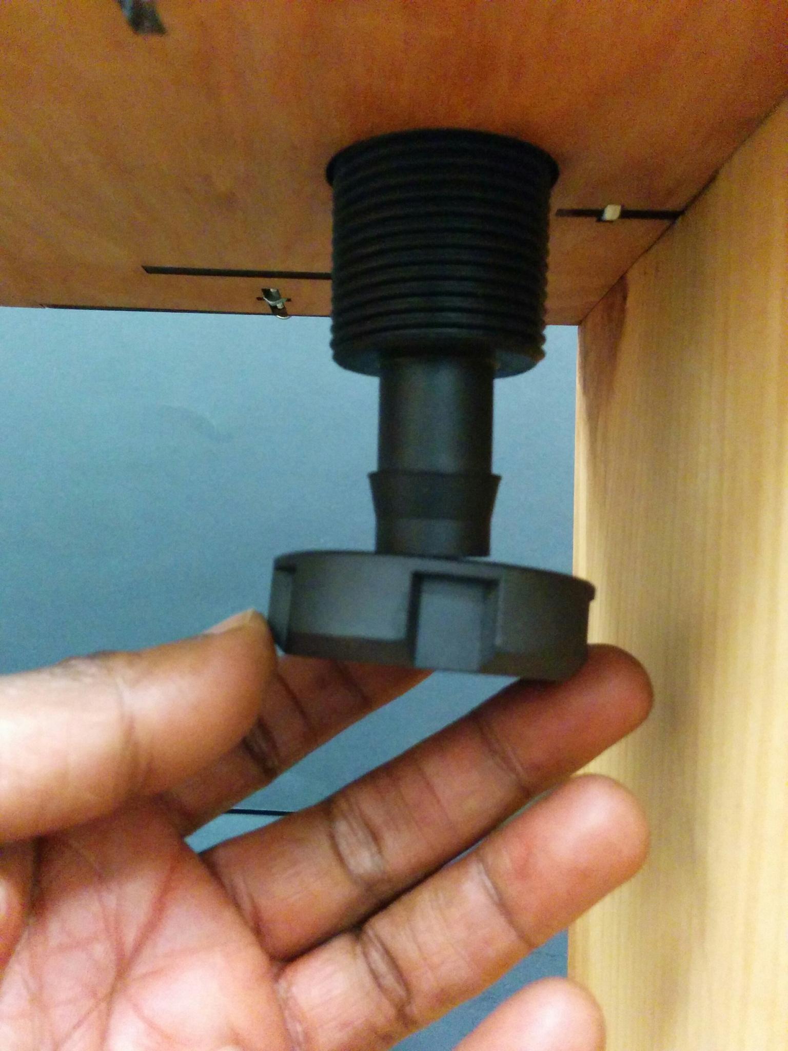
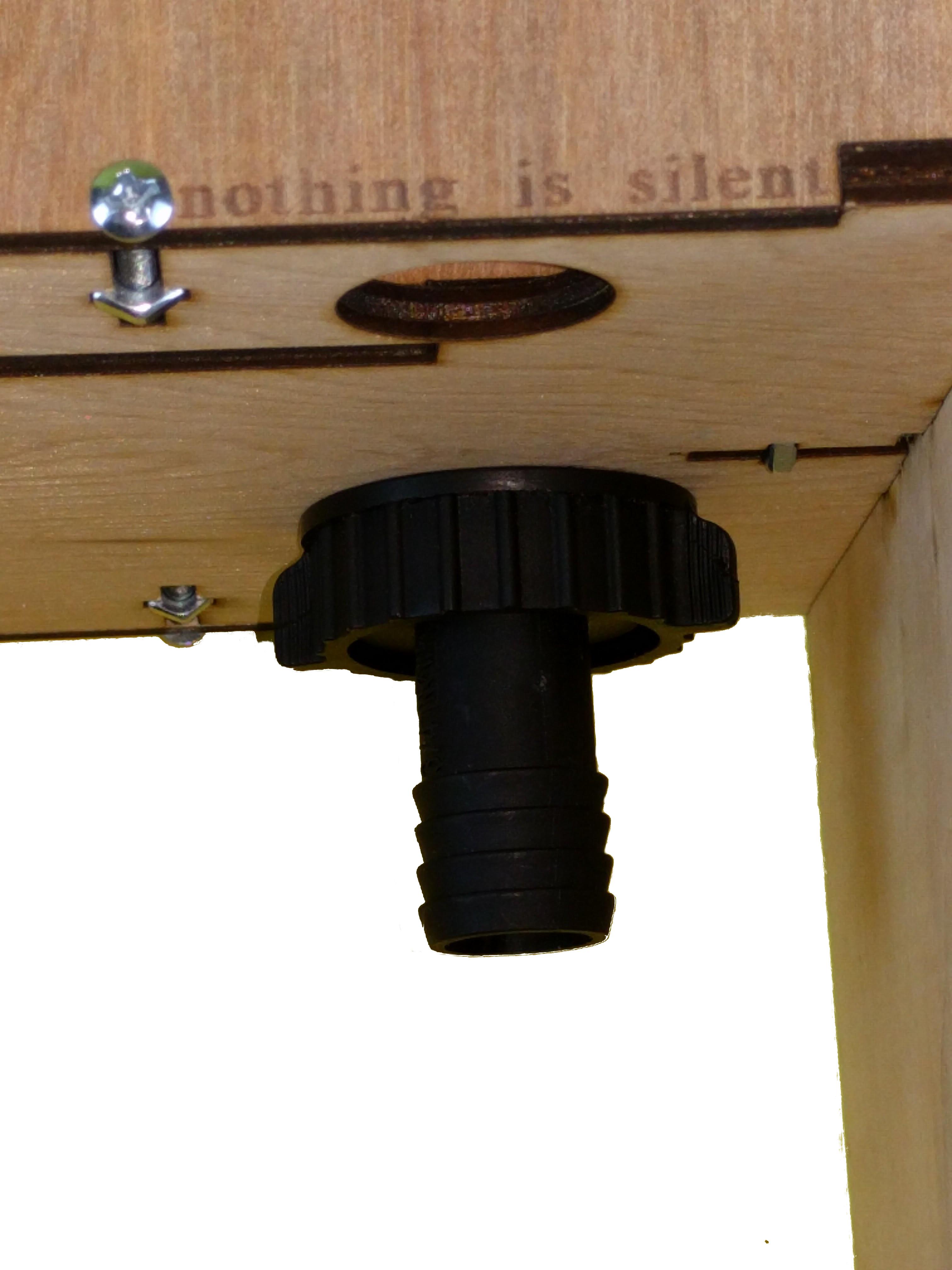
Finally, we put together the garden stand pipes using the bulk head kit shown.
A Visual Summary
All you need are fish, seeds, and a source of biological inoculation. The computer should do most of the heavy lifting for you in terms of running and visualizing the garden processes
In future Instructables, we will show how to cycle the system biologically as well show how to adapt the kit for teaching opportunities. That said, it's good for a plate of yummy organic sunflower sprouts every week.