How to Build a Quadcopter for FPV Step by Step
by JPearsonMac in Circuits > Remote Control
16118 Views, 119 Favorites, 0 Comments
How to Build a Quadcopter for FPV Step by Step
After seeing so many amazing FPV video's on youtube I really wanted to learn how to fly FPV and create some videos of my own. I looked over a lot of very helpful websites and was able to gather lots of good information to succesfully complete my first 250 quad build. This instructable is my effort to create sort of a one stop guide from a pile of parts to taking flight. I will cover the required parts, assembly (wiring soldering, ect...), flight controller programming, and offer a few practice suggestions. Thanks!
Create the XT60 Battery Lead
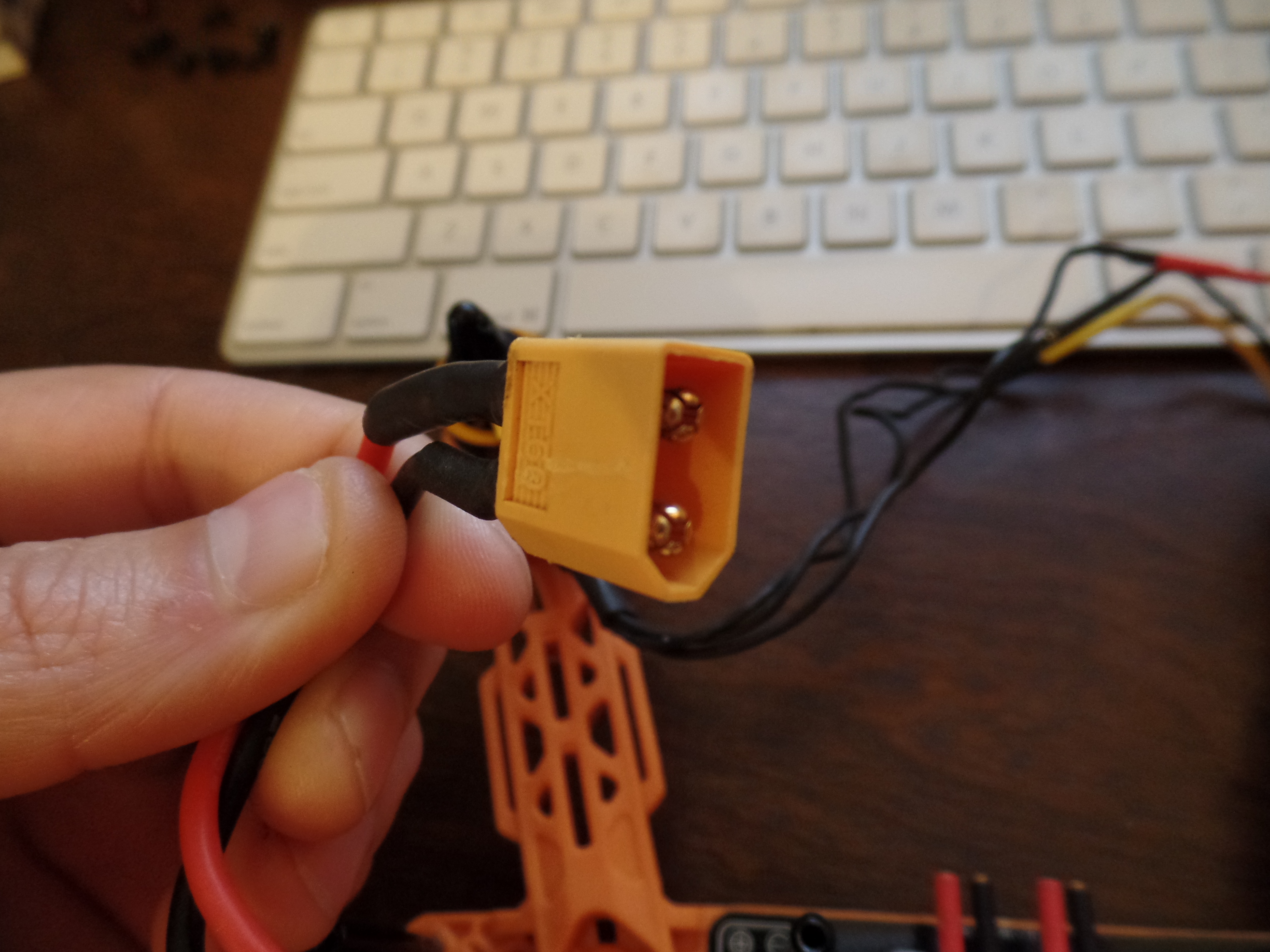
Using 7" of 16AWG wire, solder the red and black wires to the backside of the female XT60 connector. Add heat shrink over the metal connectors on the back side of the XT60 connector.
Solder XT60 Lead to the Power Distribution Board (PDB)
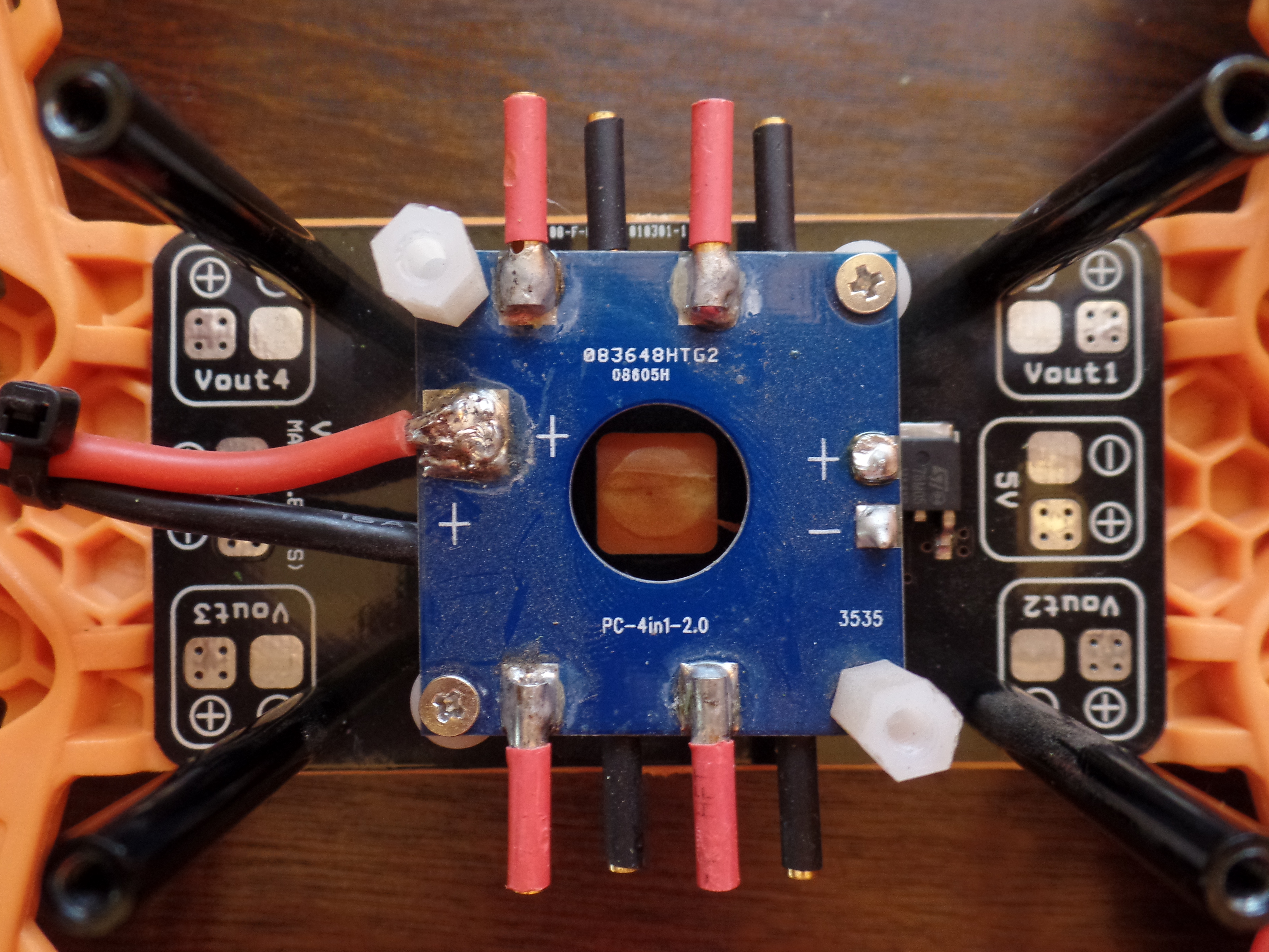
First, you'll notice I am not using the PDB that came with the frame. No good reason for this other than I already had purchased the PDB pictured and used it because the female bullet connectors came pre soldered. Before you solder the leads to the PDB don't forget to add the heat shrink to the wires.
Mount the Power Distribution Board (PDB) to the Quad Frame
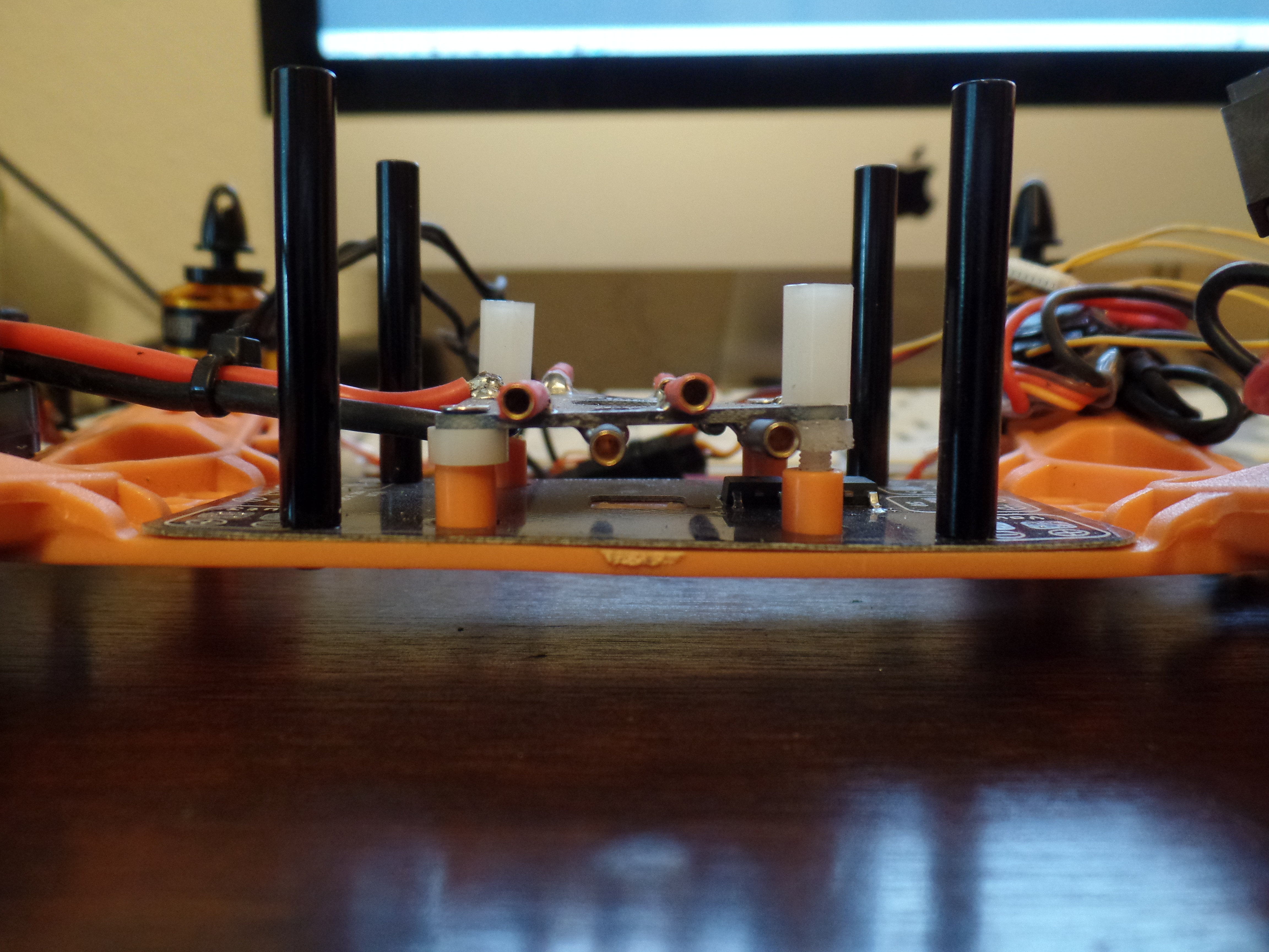
Use x2 plastics standoffs and attach to apposite sides of the PDB. The plastic standoff will be used to mount the flight controller to in a later step. Use x2 screws to attach the power distribution board to the frame.
Solder Male Bullet Tip to Motor Leads
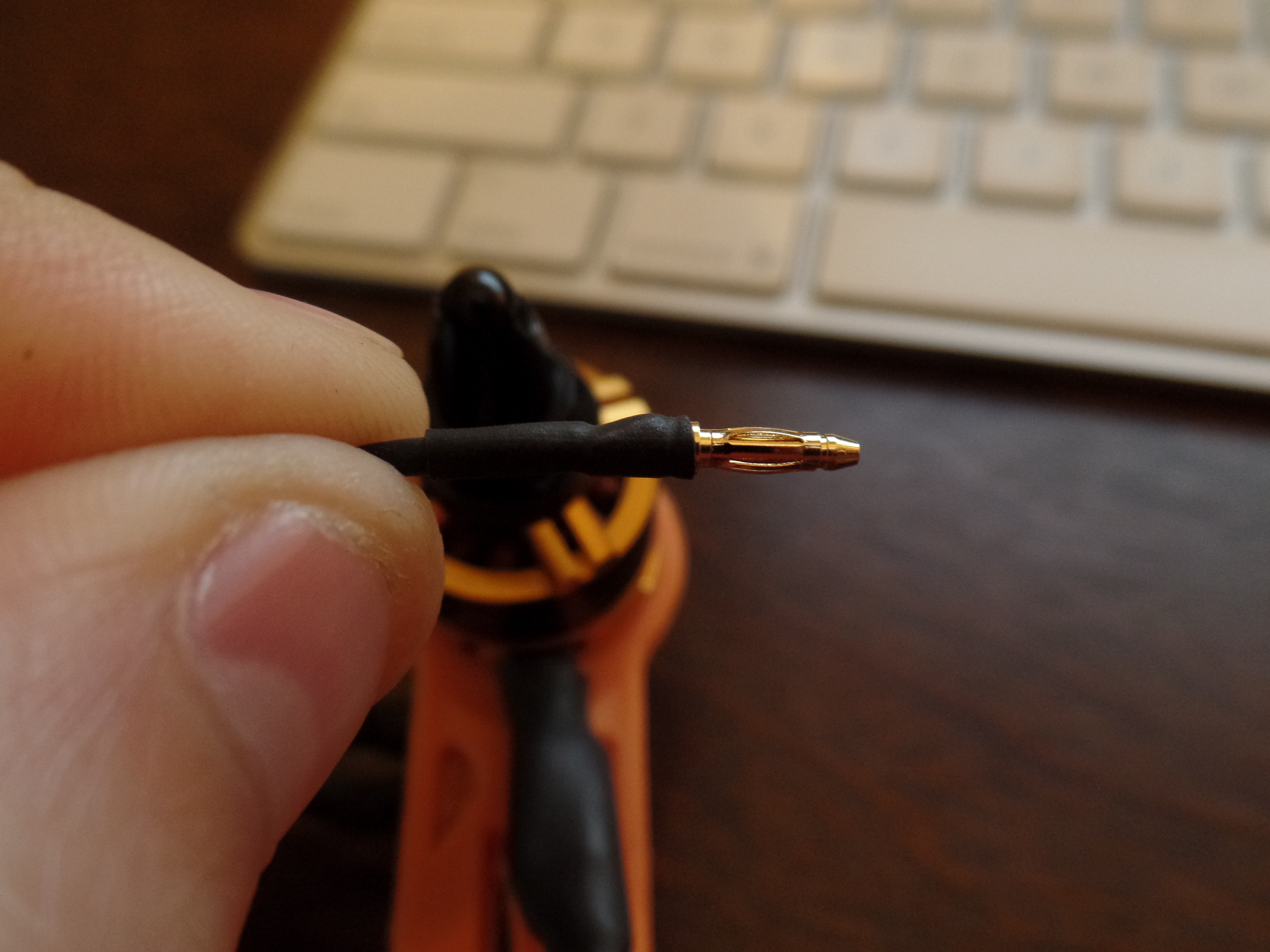
The motors I used came with the bullet connectors.
Mount Motor to Frame Arms
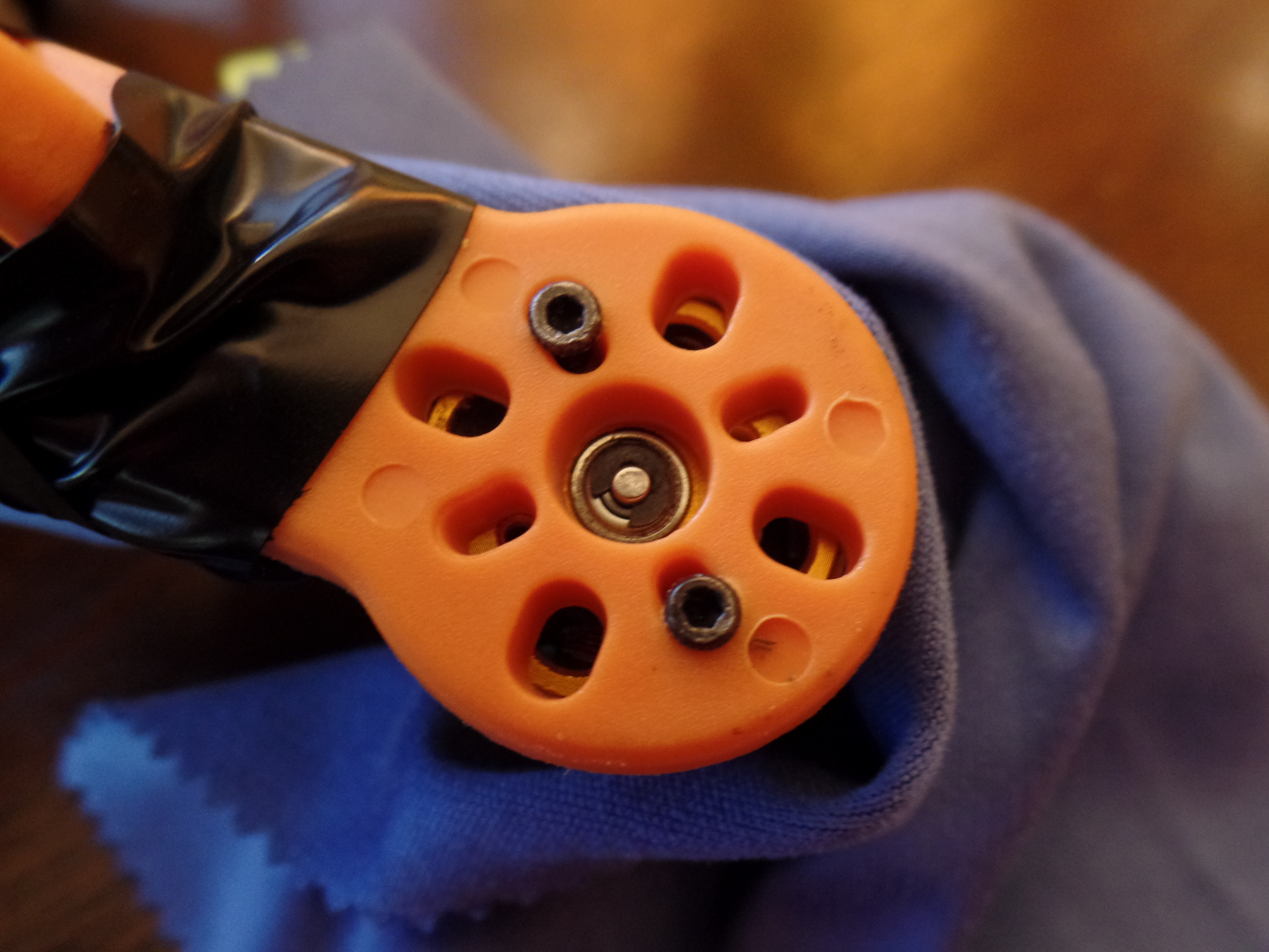
Use the screws supplied with the DYS motors.
Connect ESC to Motor Leads
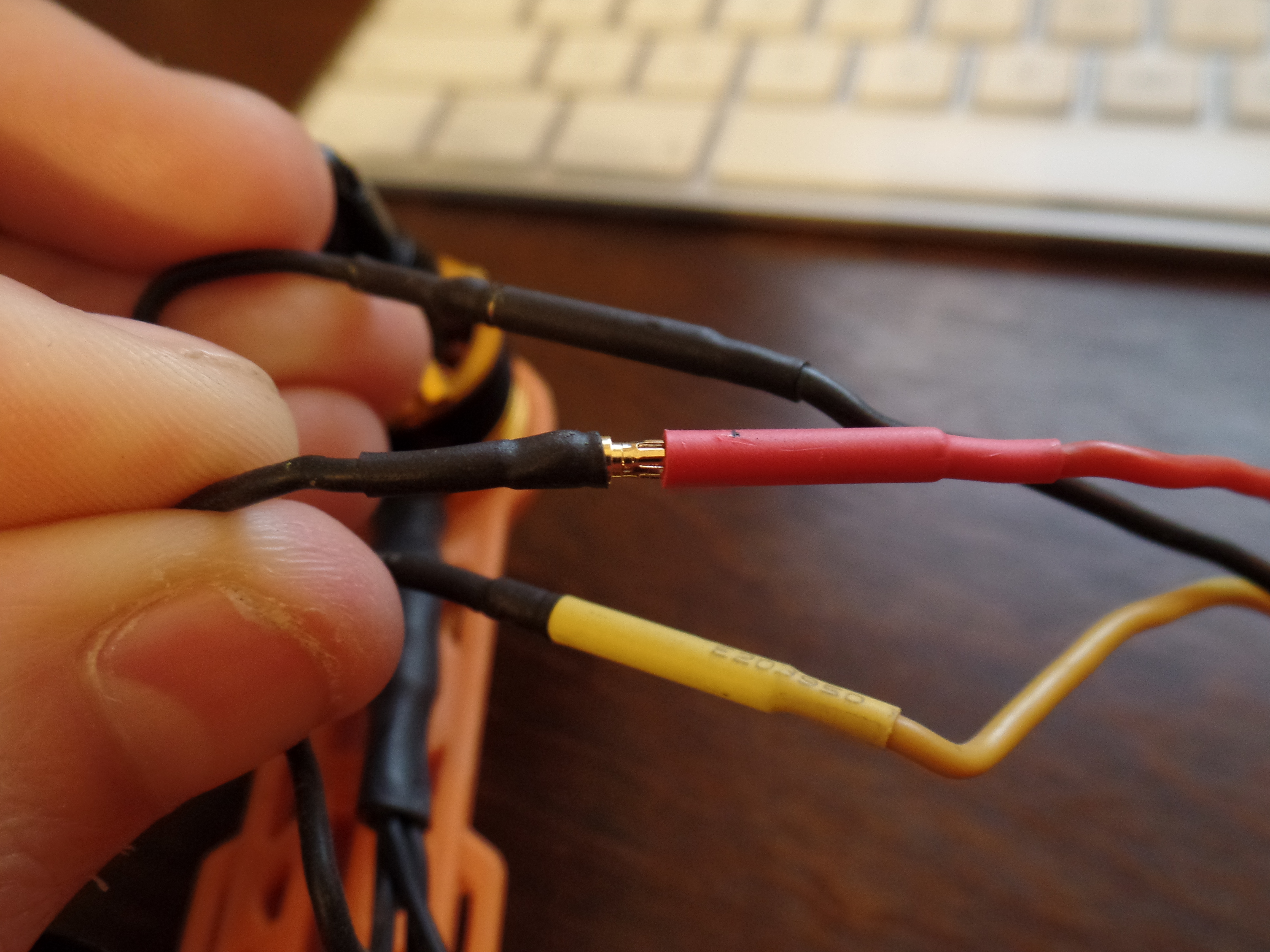
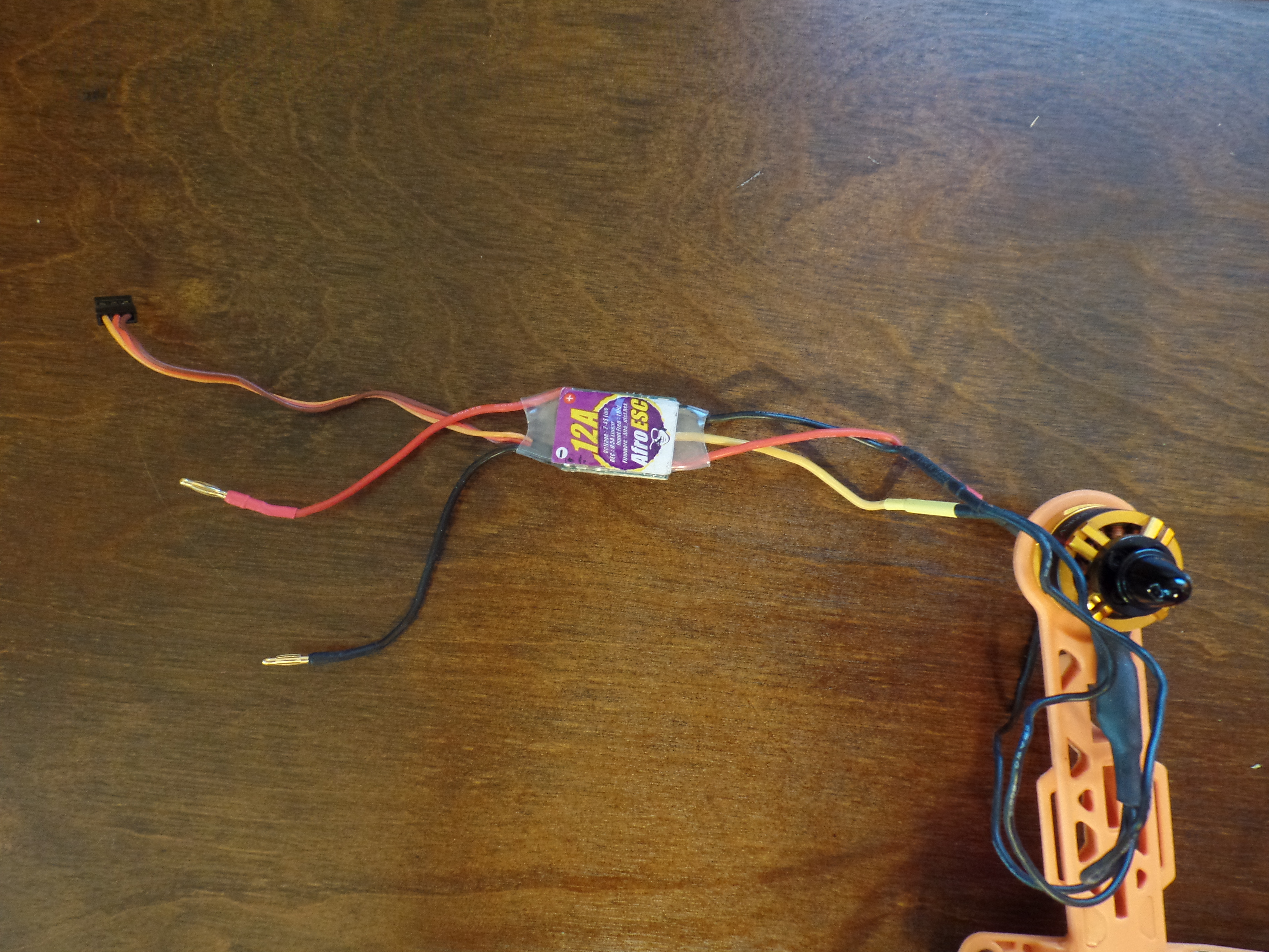
You will have 3 wires coming from the motor that will all be black. Connect the bullet connecters from the black motor leads in to the ESC female bullet connectors (the order doesn't matter at this point).
Connect ESC Power Leads to PDB
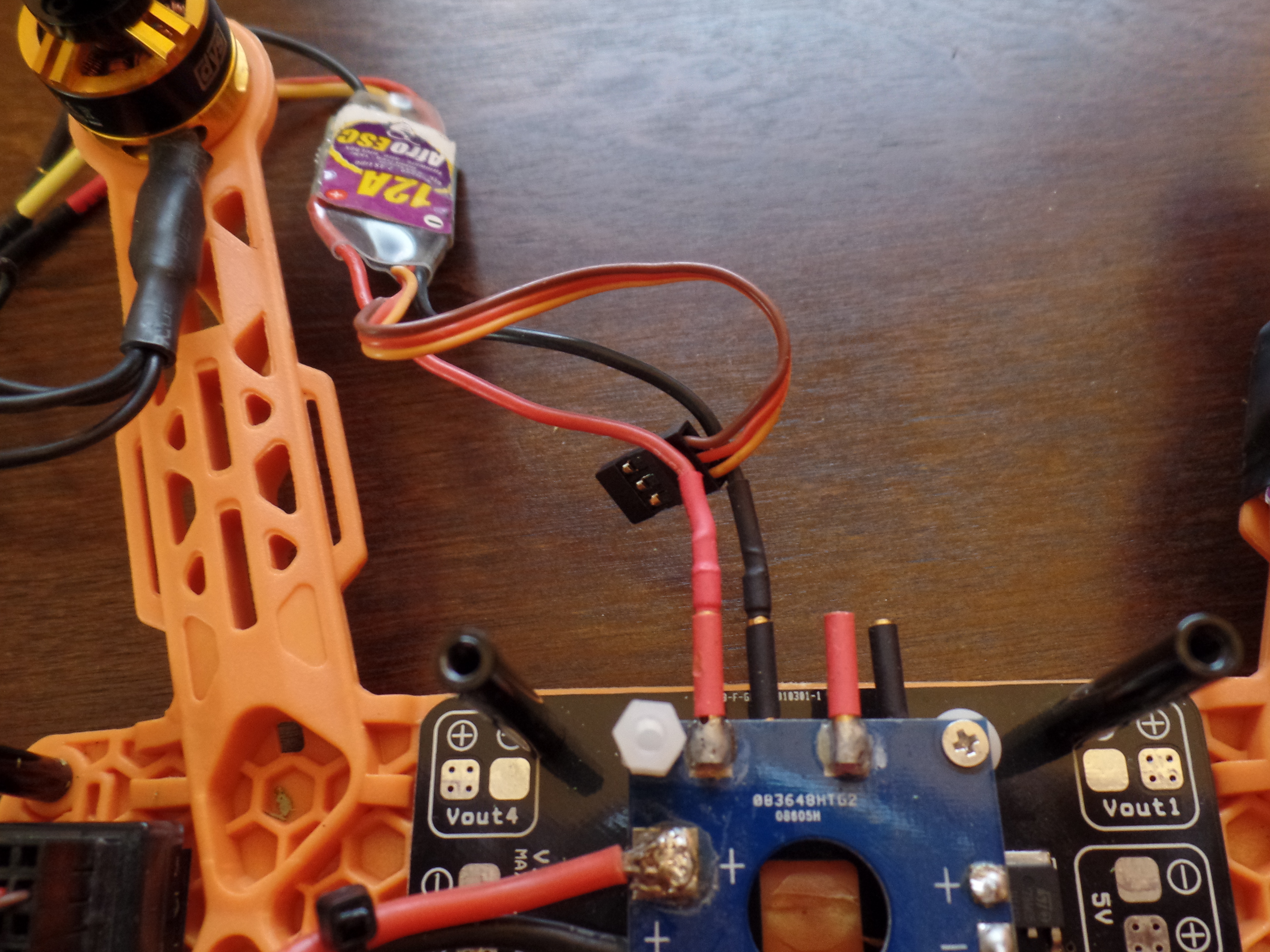
Plug the black and red male bullet connectors on the ESC in to the black and red female bullet connectors on the PDB.
Repeat Steps 4 Through 7 for the Remaining 3 Motors and ESC's
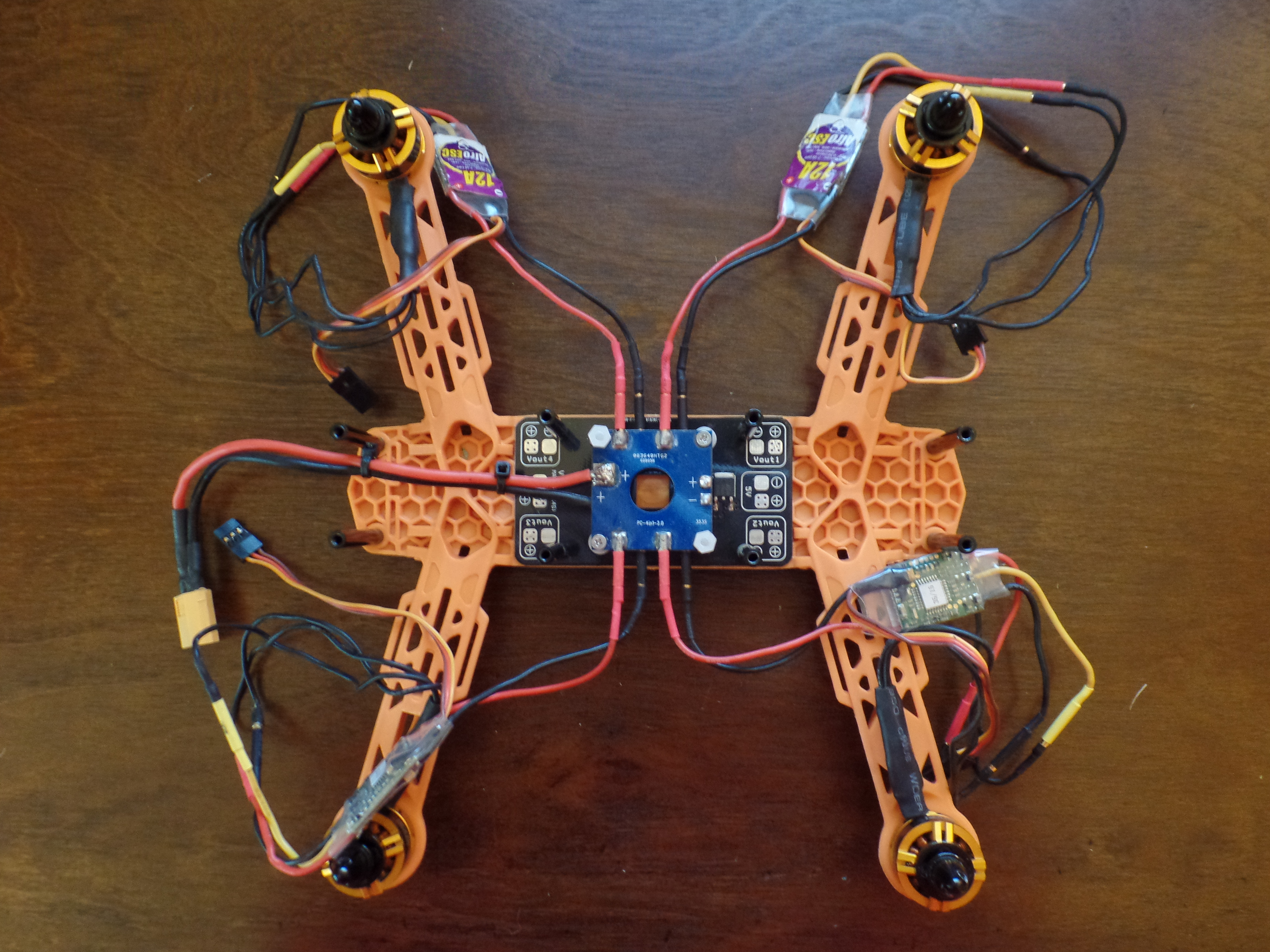
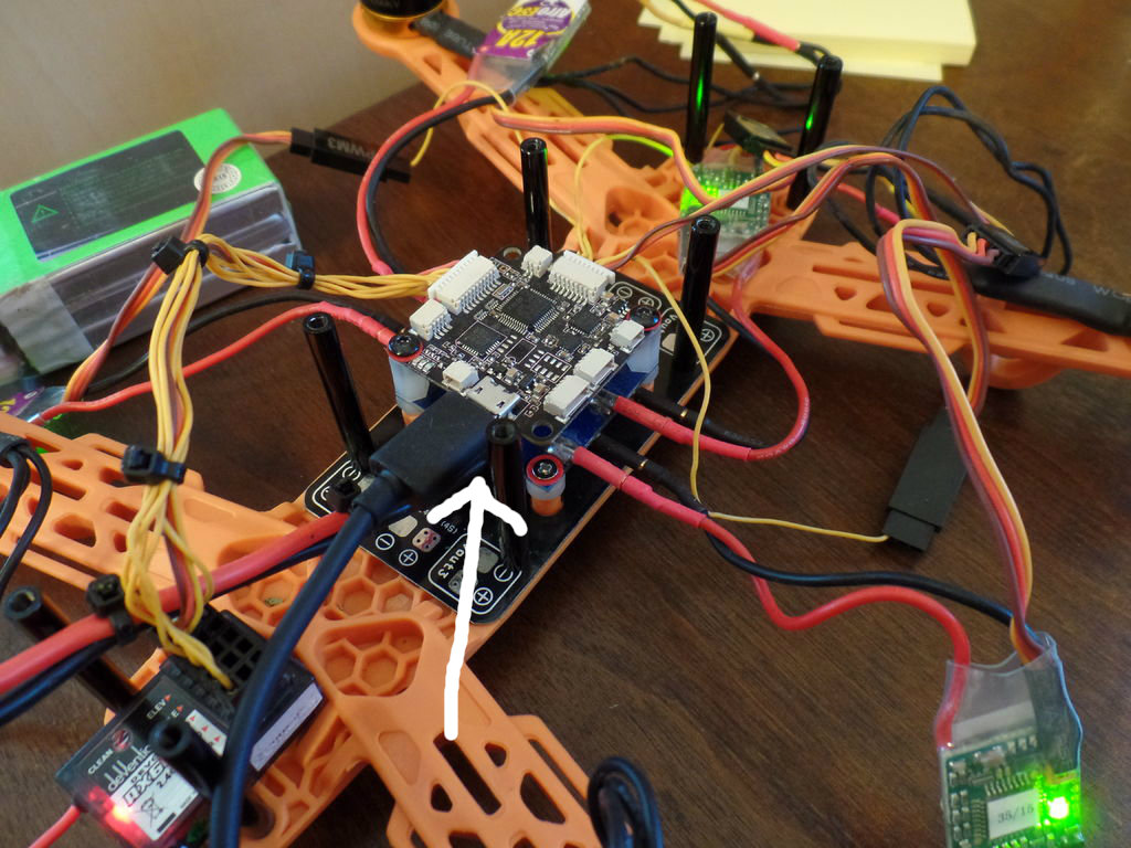
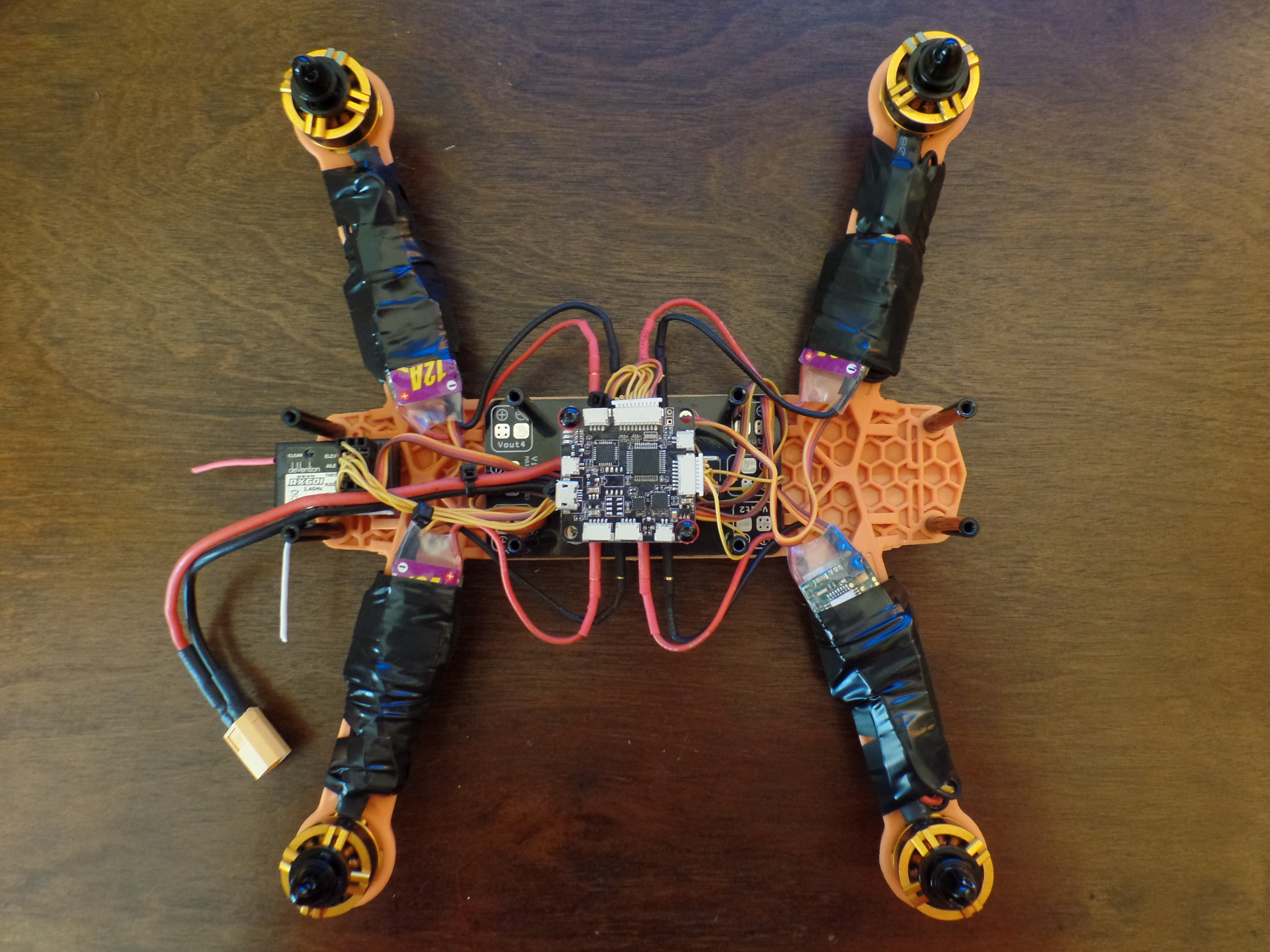
Mount Flight Controller
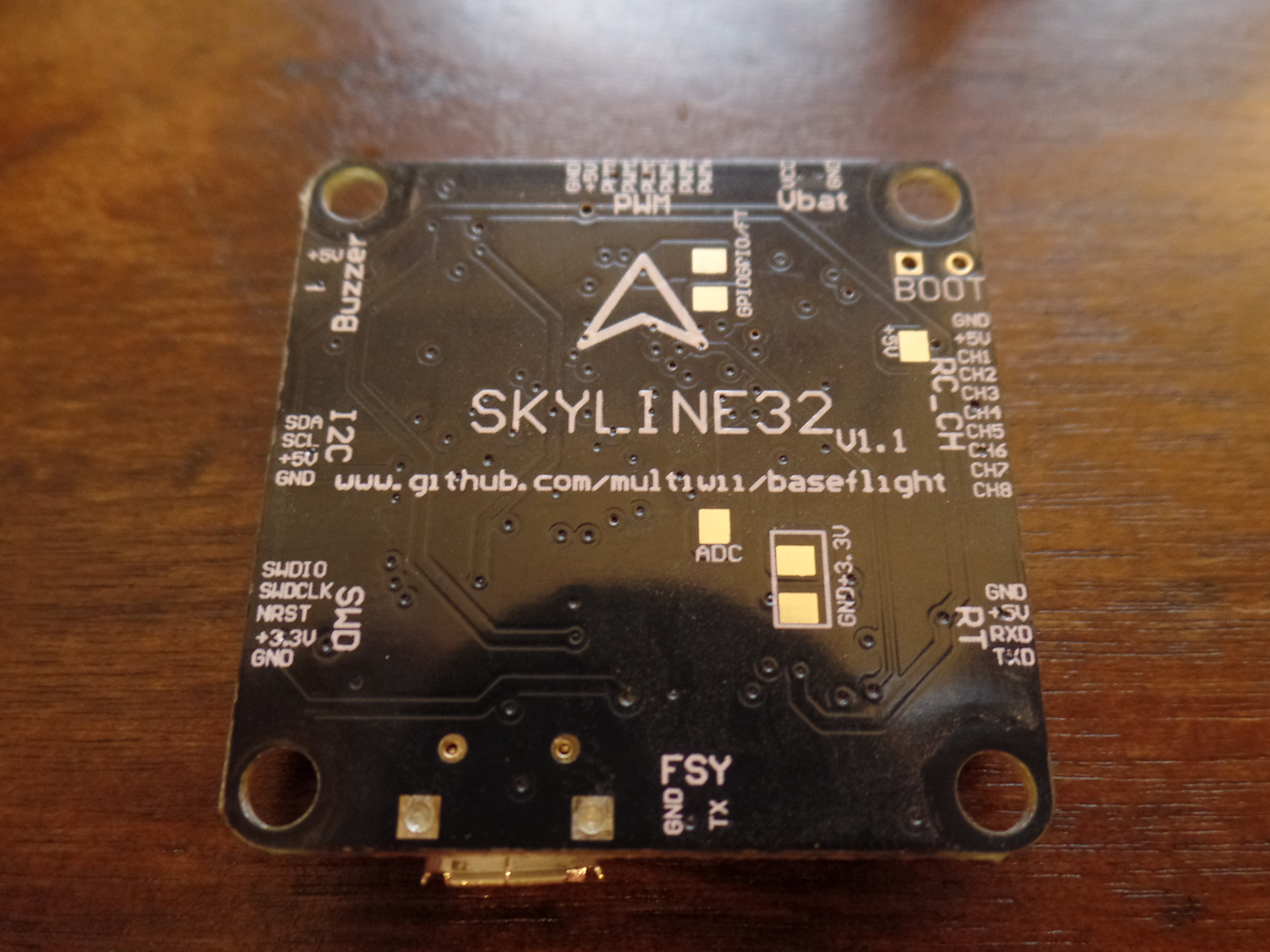
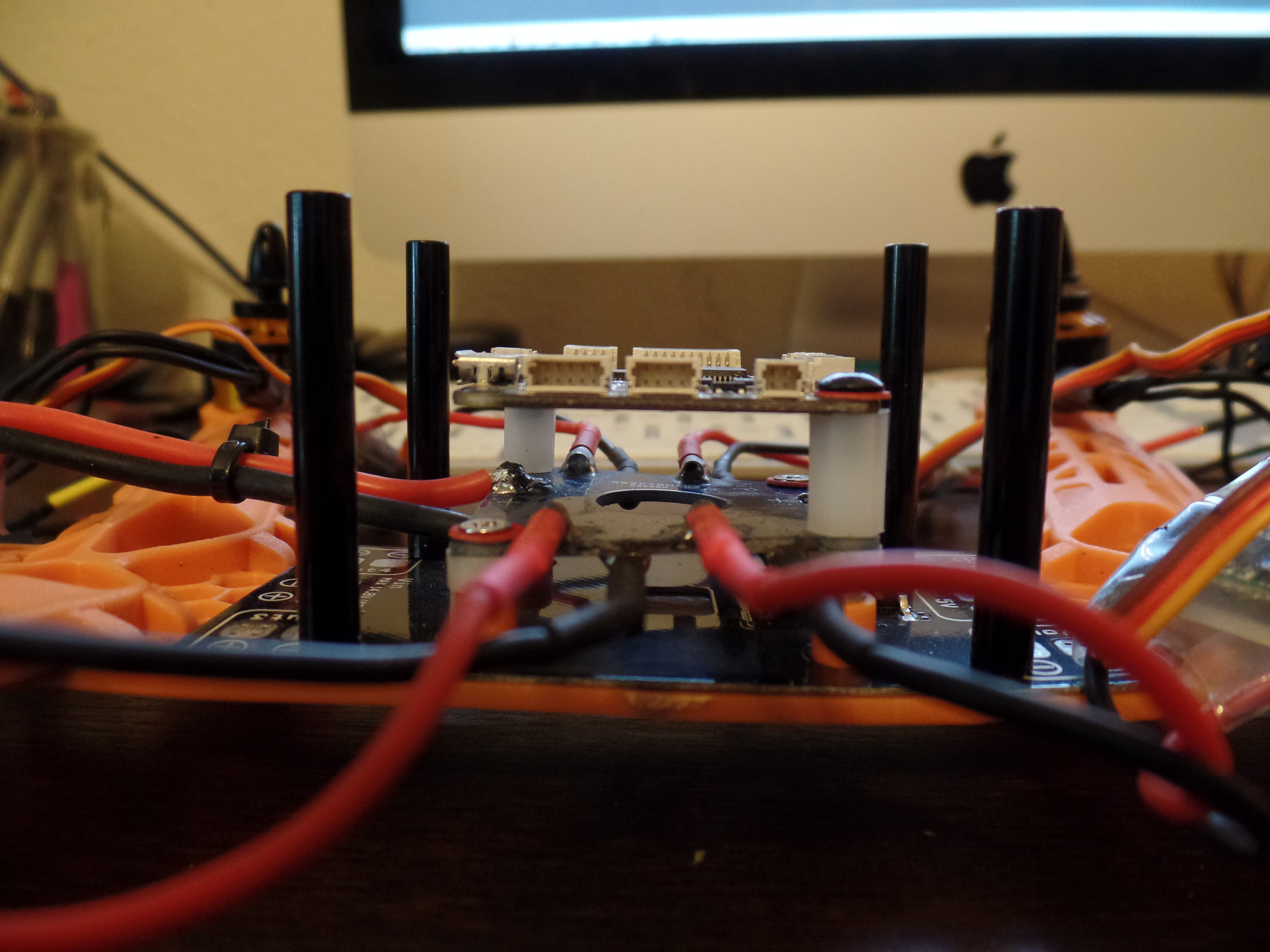
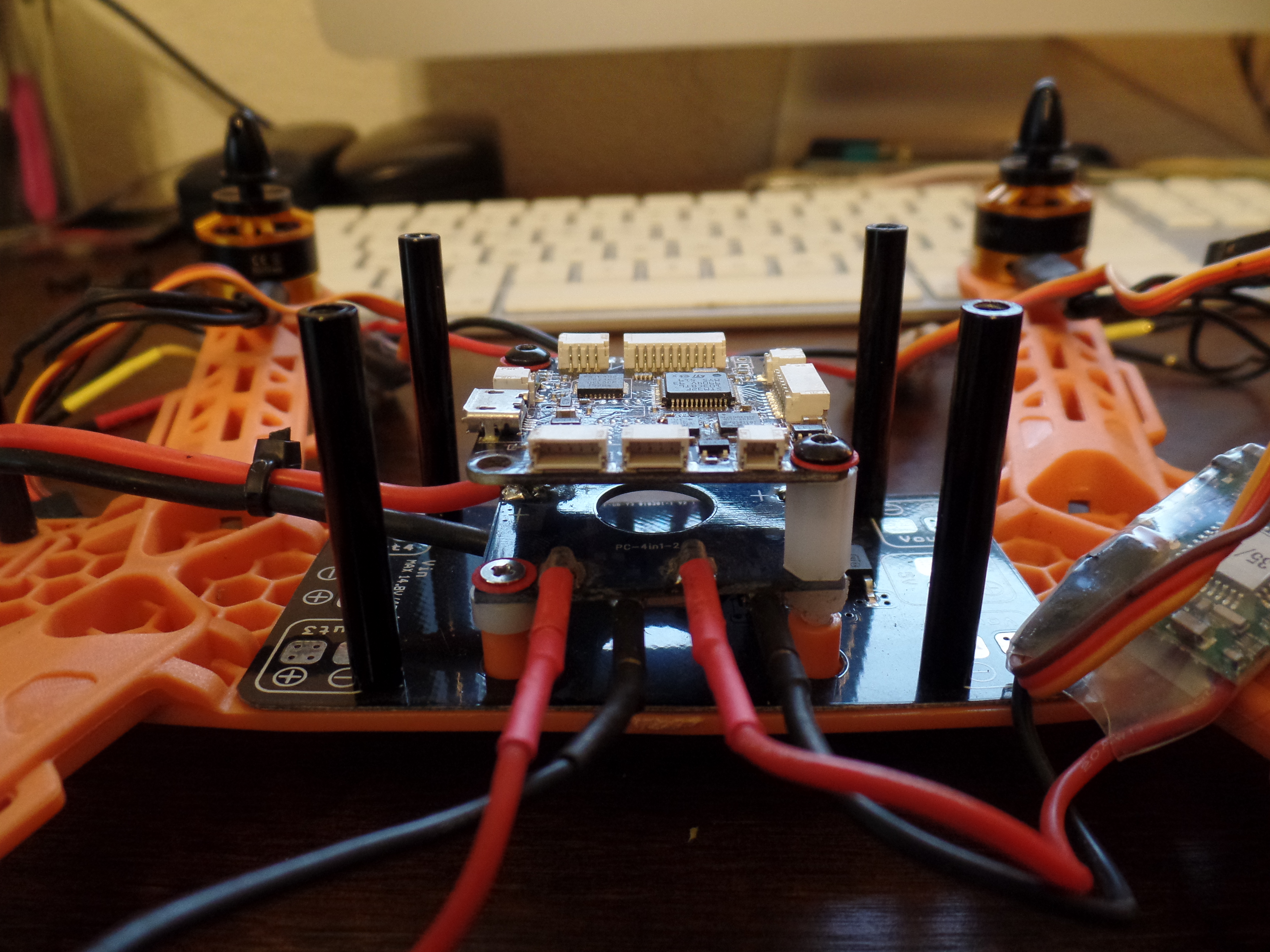
Take note of the arrow on the bottom of the flight controller. The arrow needs to point to the front of the quad. Place the flight controller on top of the plastic standouts and secure with screws.
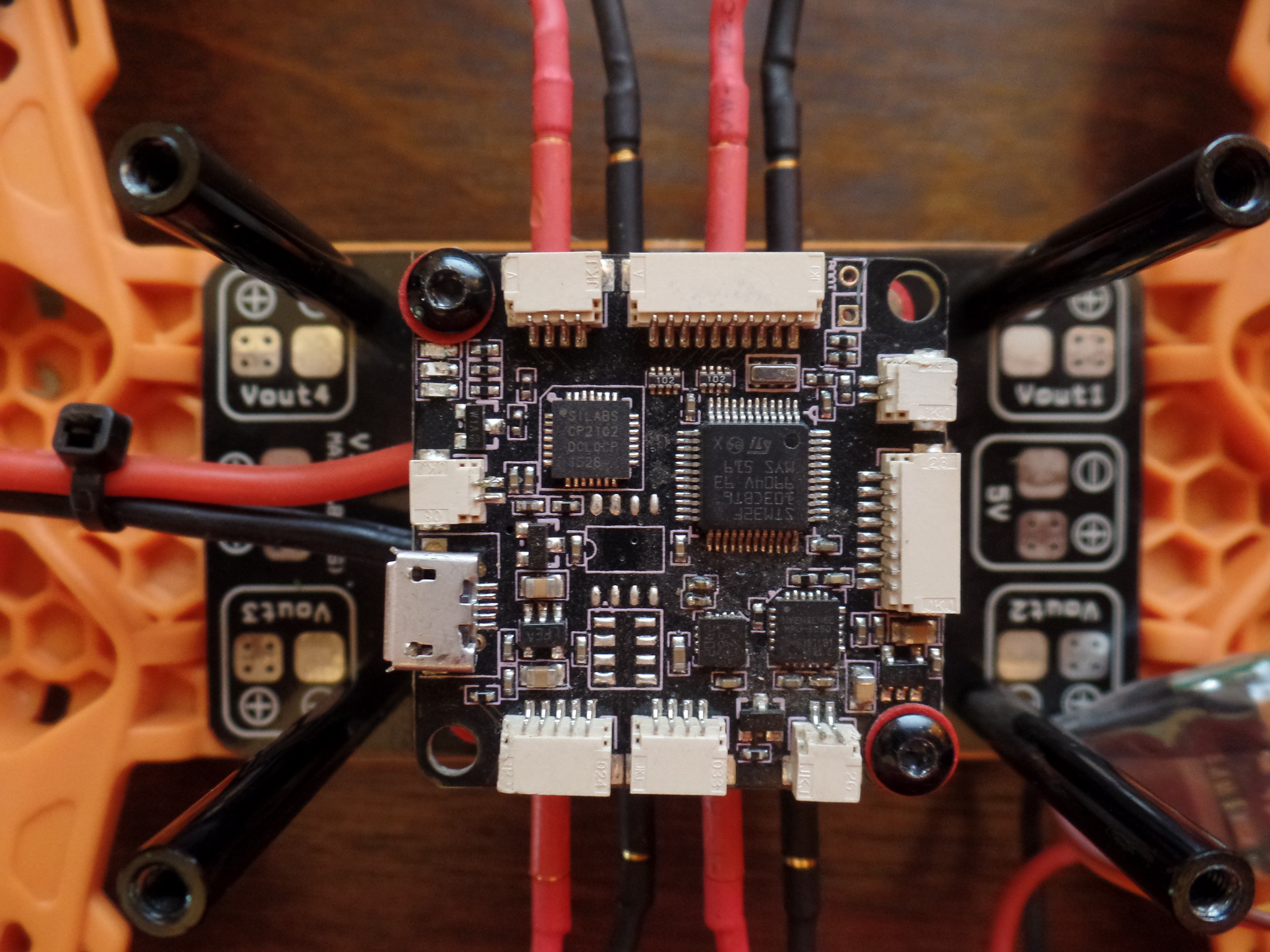
Plug PWM Wire Harness to Flight Controller and ESC's
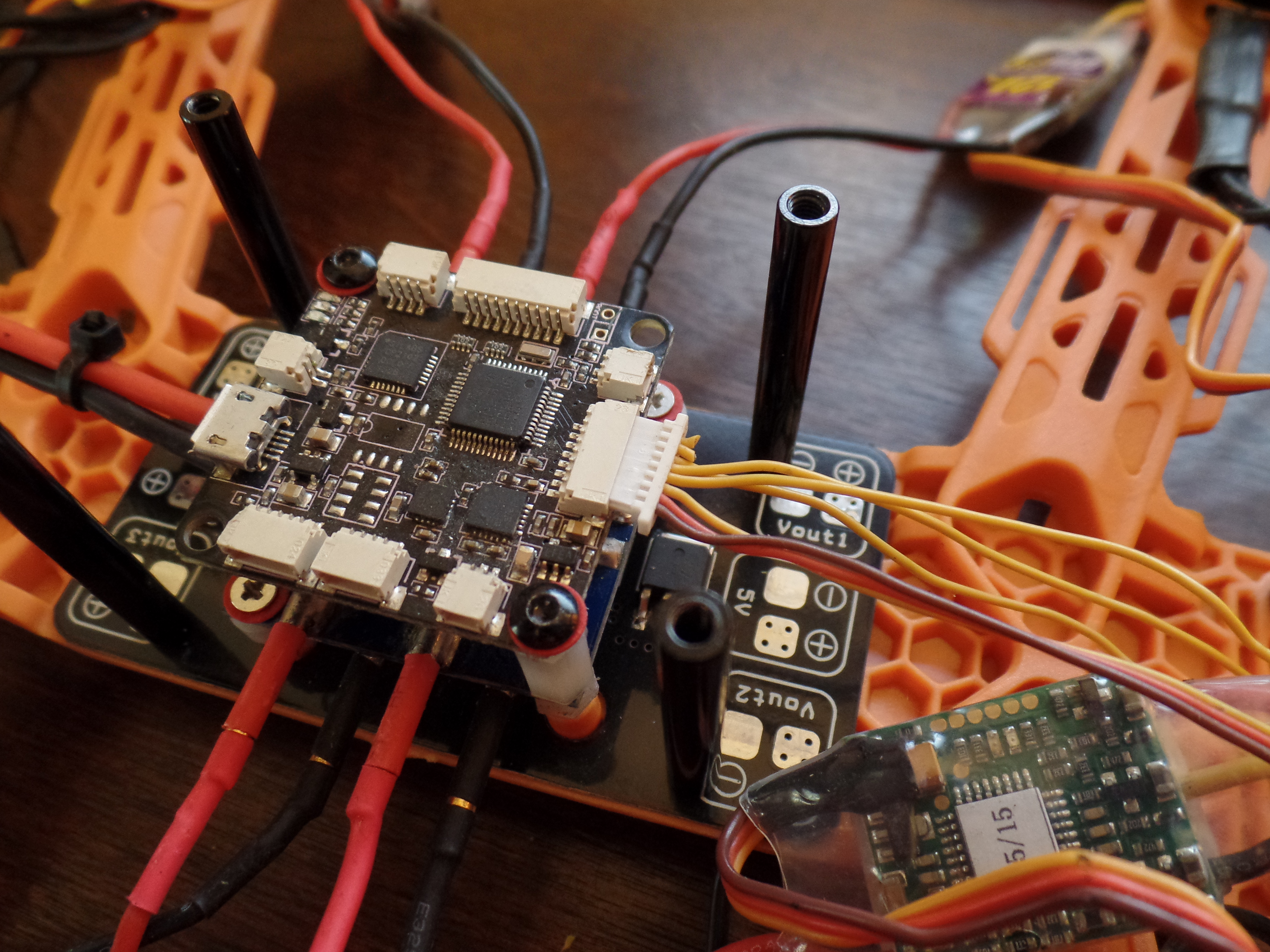
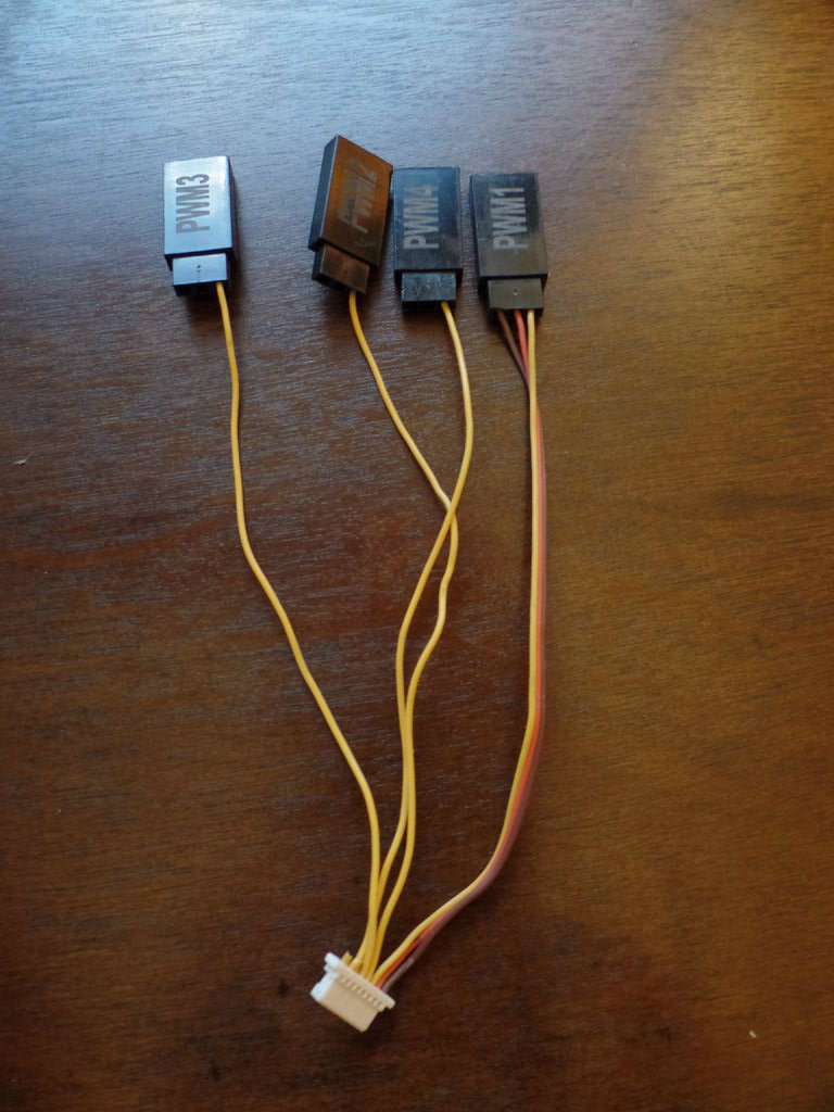
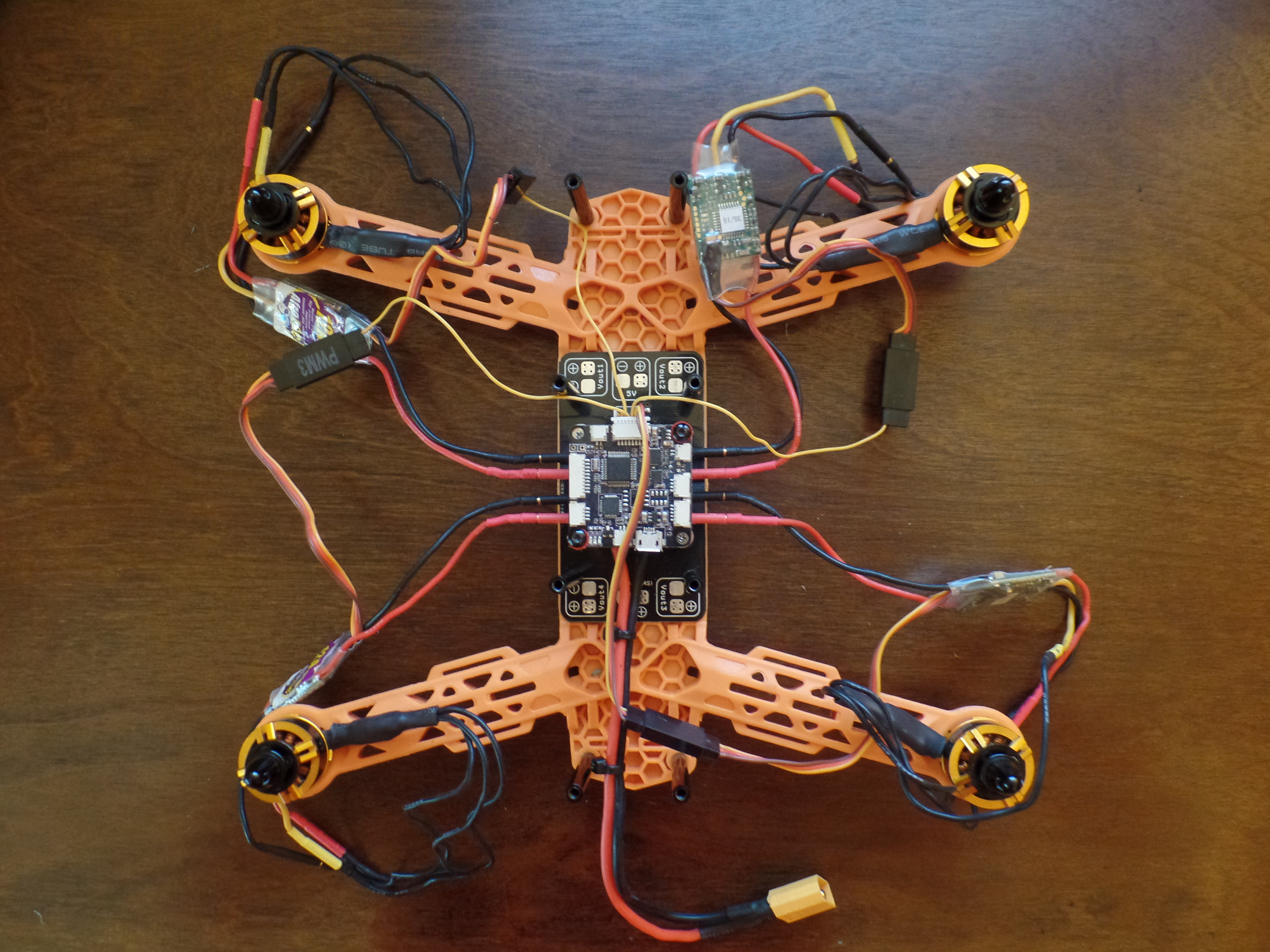
Plug the wire harness in to the flight controller and connect the ESC's to the wire harness in the following order:
- PWM 1 - Right Rear
- PWM 2 - Right Front
- PWM 3 - Left Rear
- PWM 4 - Left Front
Connect Battery to Make Sure There Is Power to the Flight Controller
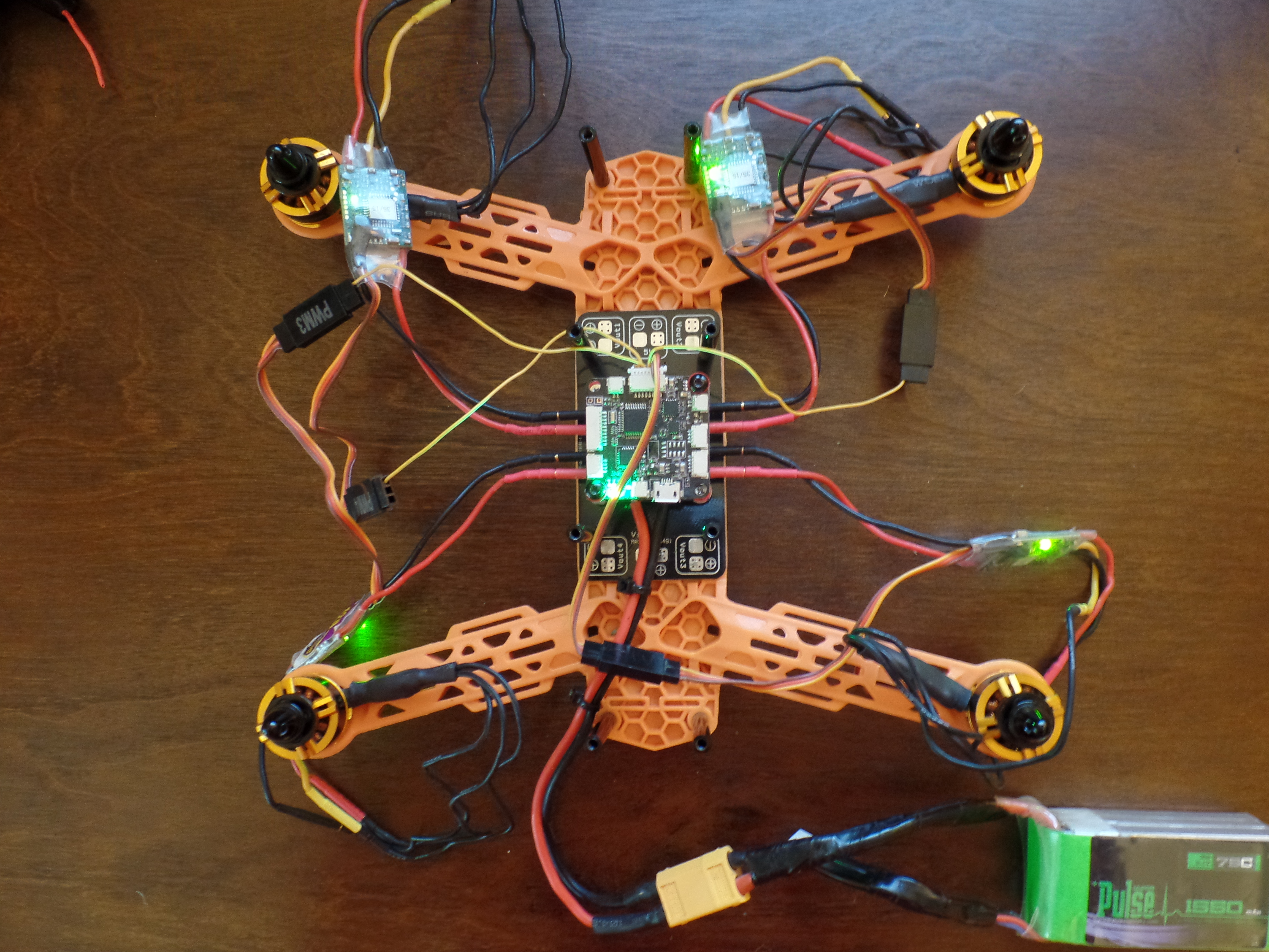
WARNING! Please remove all props from the motors!
We can now connect a 3s or 4s LiPO to see if all of our connections are working. The ESC's and flight controller should flash red and then stay solid green. You will also hear and audible tone come from the ESC's. The ESC's have 5v UBEC's built in so the voltage coming in from the battery will be stepped down to 5v.
Connect RC Wire Harness to Receiver
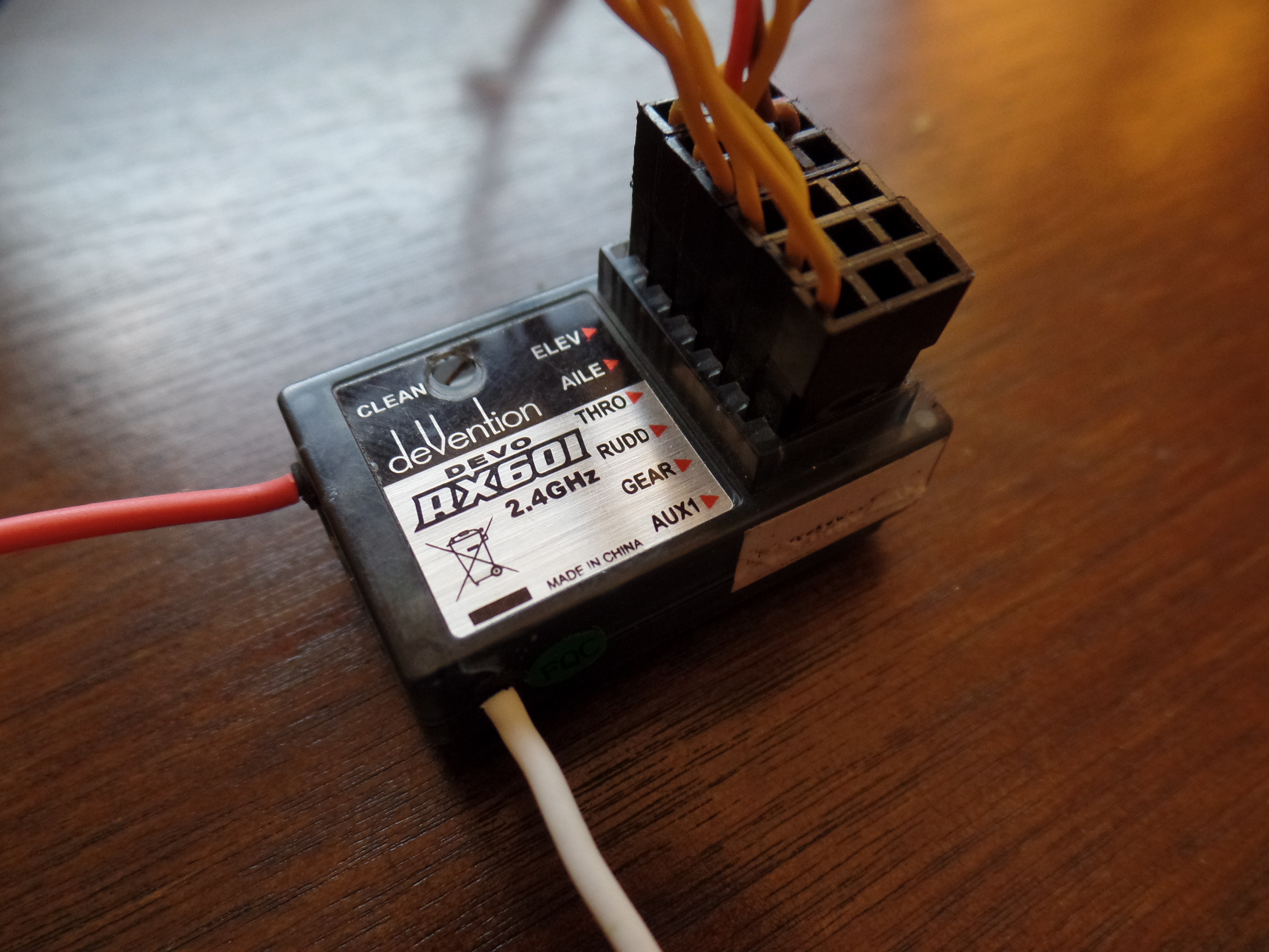
Connect the RC wire harness in to the receiver in the following order:
The values below on the left are listed on the reciever and the the channel numbers are marked on the wire harness connectors.
- ELEV - CH2
- AILE - CH1
- THRO - CH3
- RUDD - CH4
- GEAR - CH5
- AUX - CH6
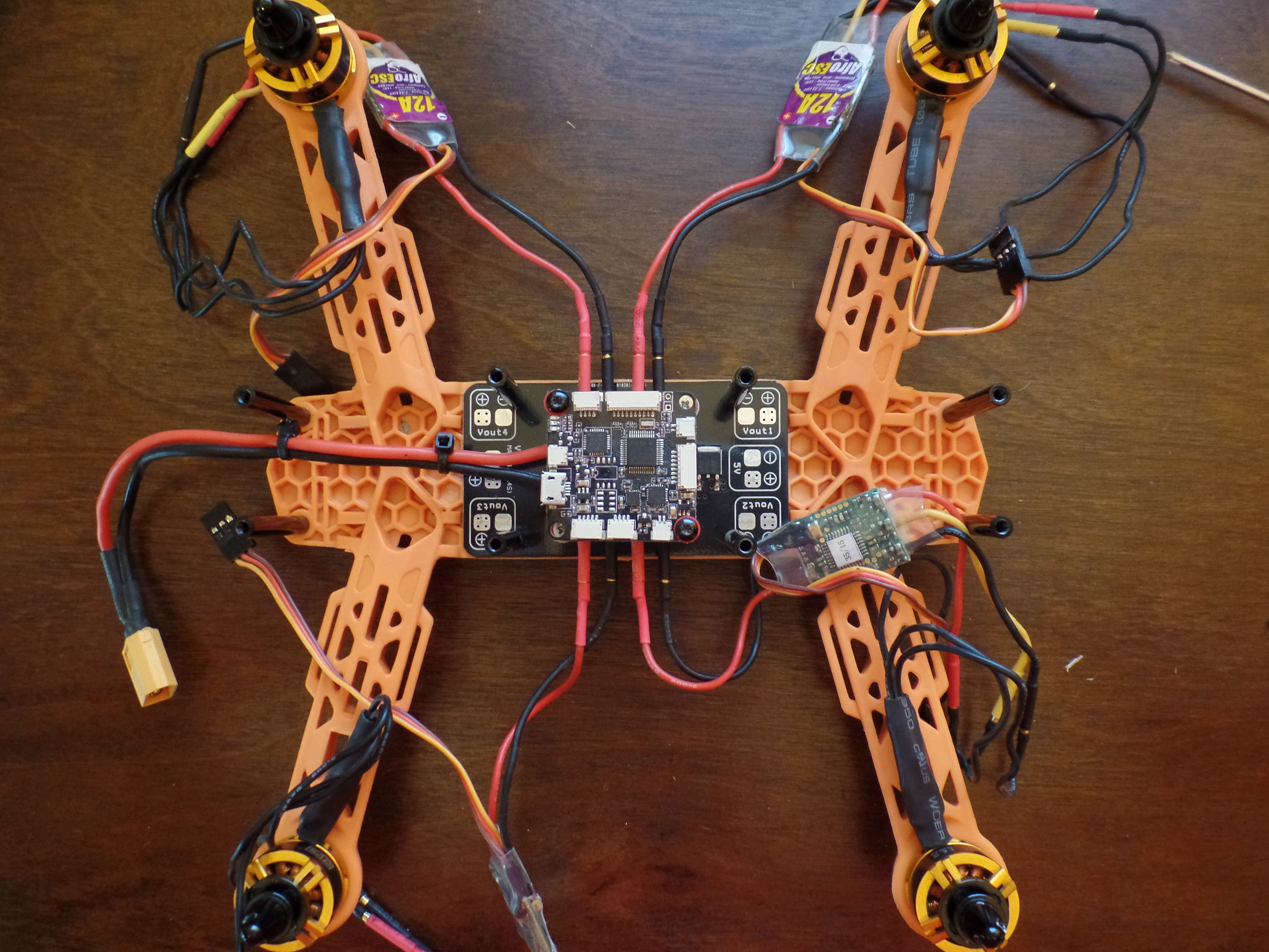
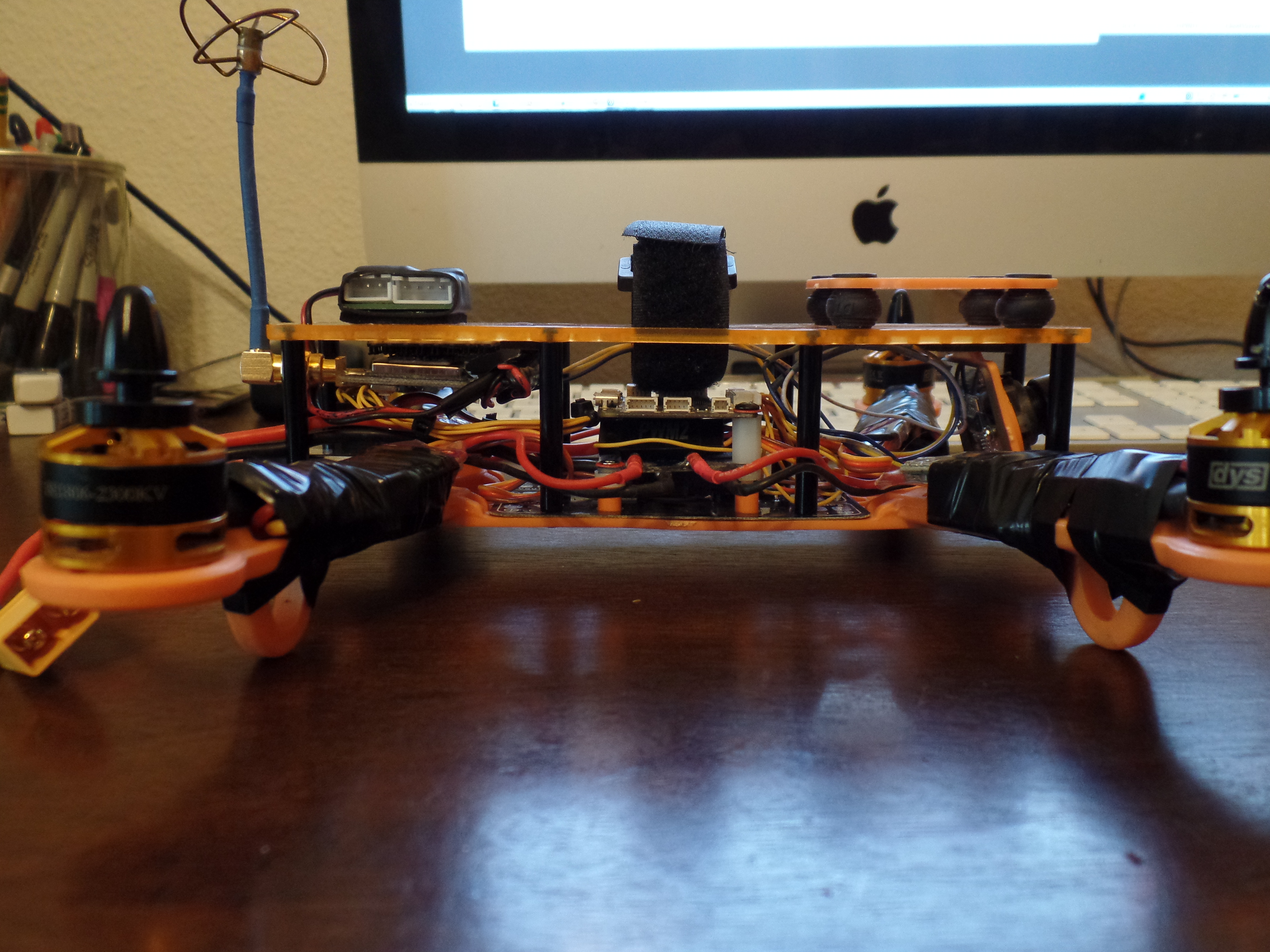
Mount Receiver to Quad Frame and Connect the Wire Harness to the Flight Controller
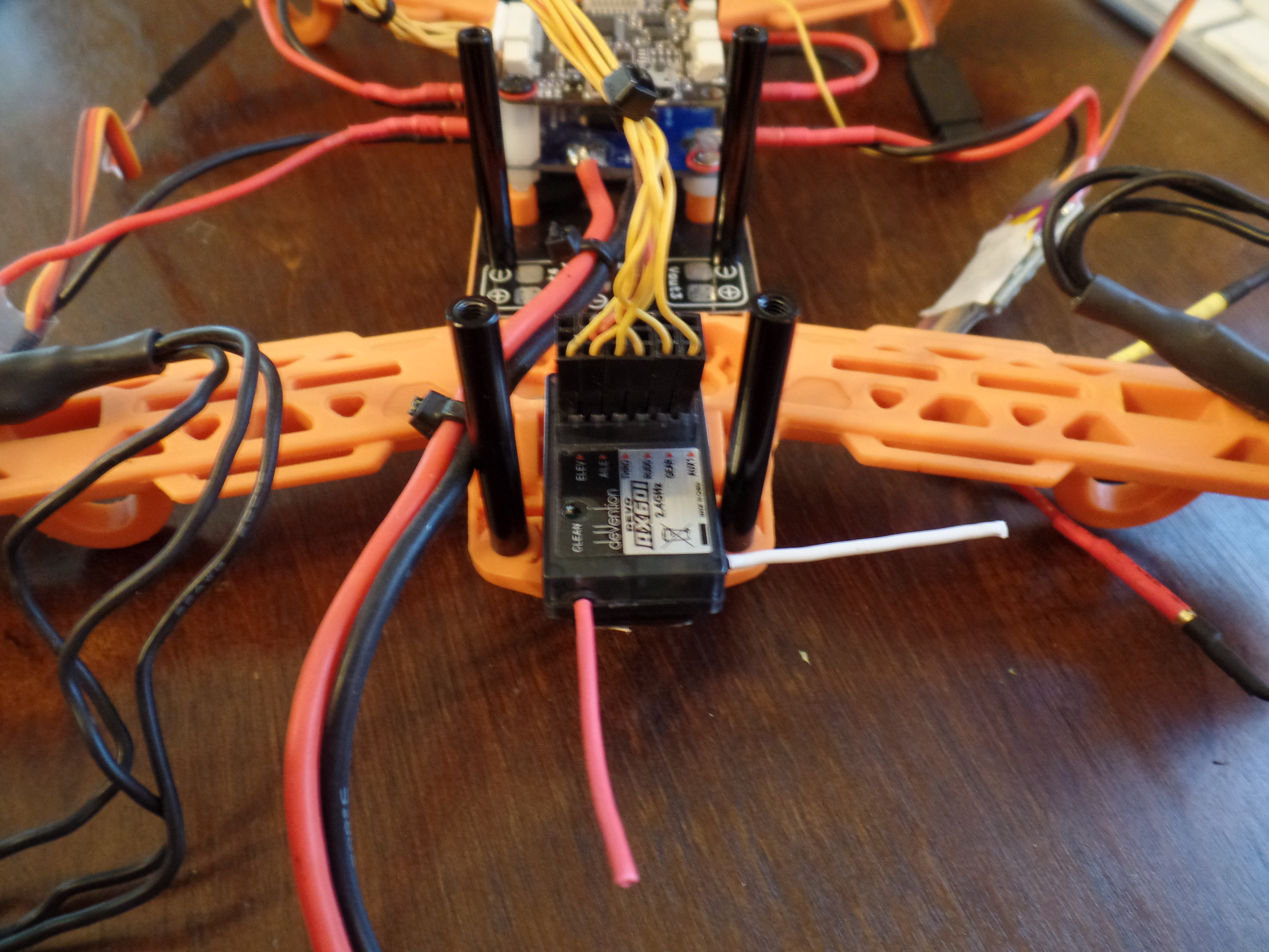
Find a good spot to mount the receiver. You want the receiver to survive in the event of a crash and there will be lots of crashing. I used 3M double sided foam tape to secure the receiver to the rear of the quad. The RC wire harness connect to the side of the flight controller. The plugs on the flight controller for the wire harness' are all different sized so there is no risk of plugging to the wrong port on the flight controller.
Bind the Transmitter and Receiver
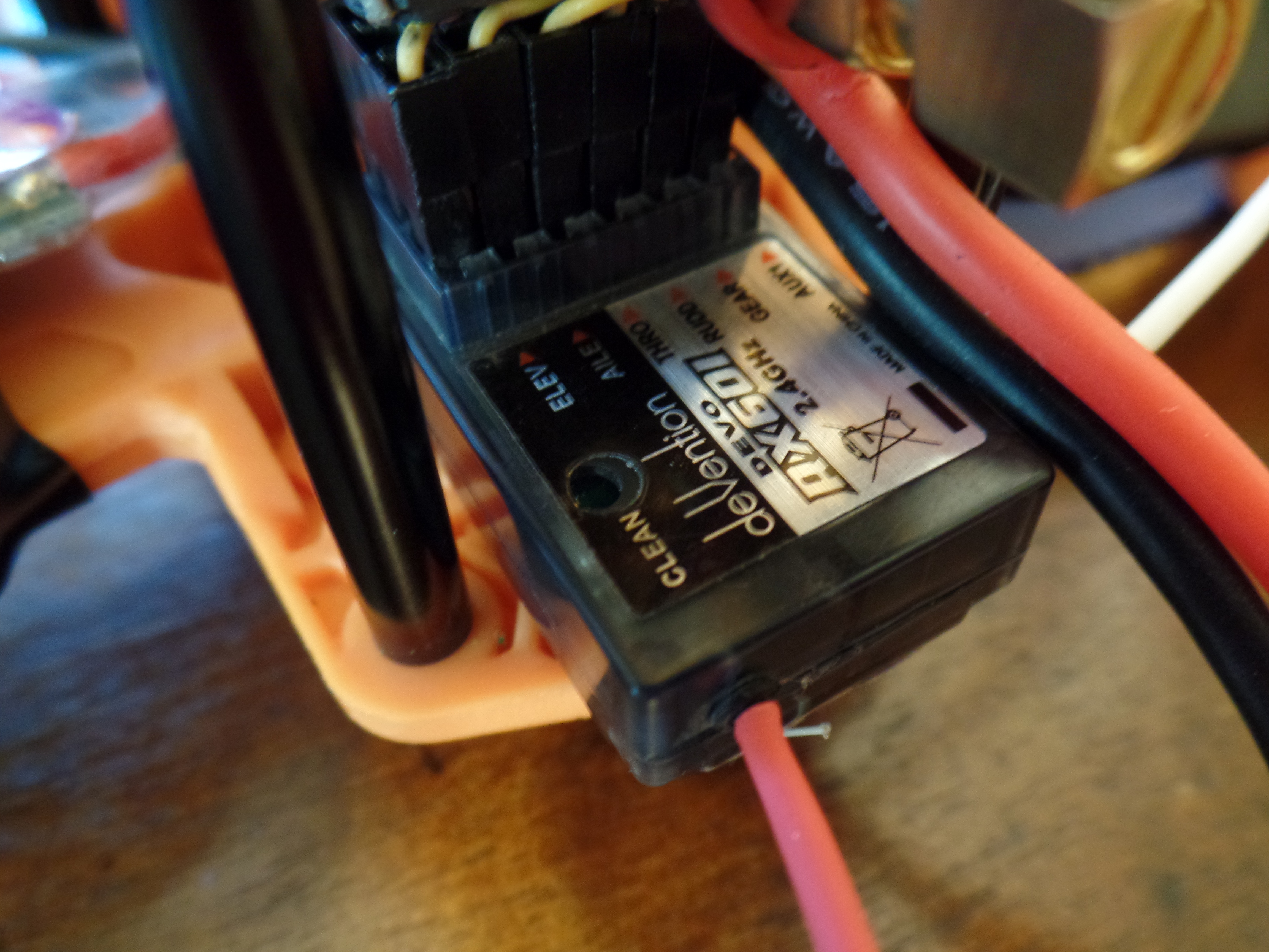
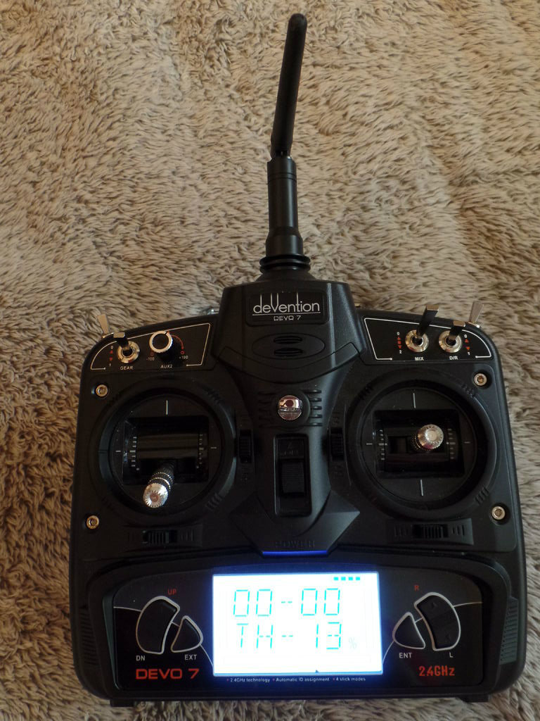
I was able to bind the transmitter and receiver by just power both on and moving the throttle up for a brief second and then back down to 0. Once binded the receiver will show a solid red light. I have attached the Devo 7 user manual in case you run in to any issues.
Downloads
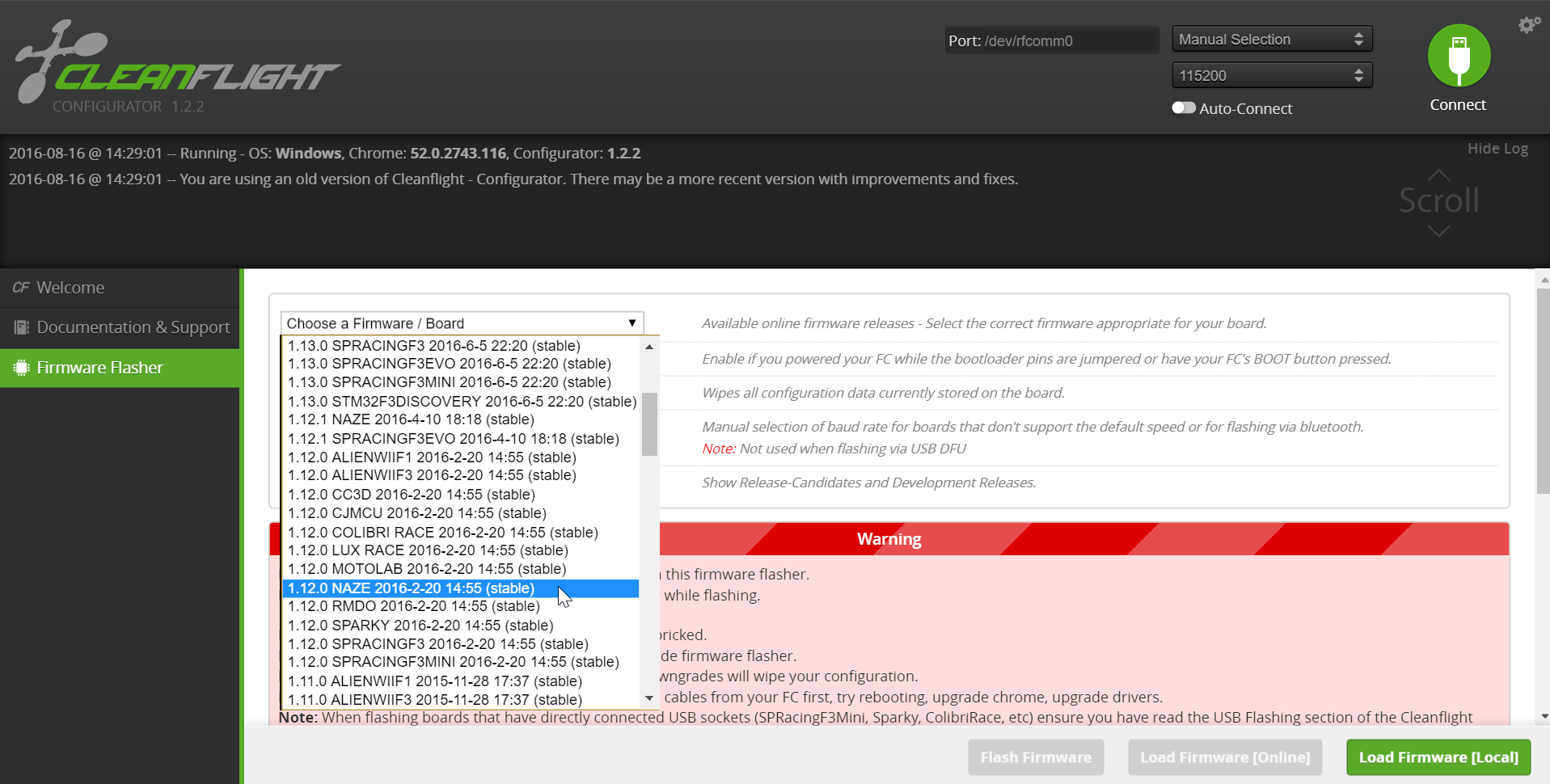
Flash Flight Controller With CleanFlight
Again, you will want to make sure your props are NOT attached!
Download CleanFlight for Google Chrome browser if you have not already.
- Attach battery
- Plug the USB cable in to your computer and then into the micro USB on the flight controller.
- Open CleanFlight and hit connect (you may need to select the correct comport).
Once connected, click the firmware flasher from the menu on the left. Select firmware version v1.12.0 Released 2016-02-20 from the drop down on follow the directions within CleanFlight to flash the flight controller.
CleanFlight Settings
Motor orientation
If one of the motors is not spinning in the desired direction simpy switch any two of the 3 leads from the ESC to the motor.
- Right Rear - CW
- Right Front - CCW
- Left Front - CW
- Left Rear - CCW
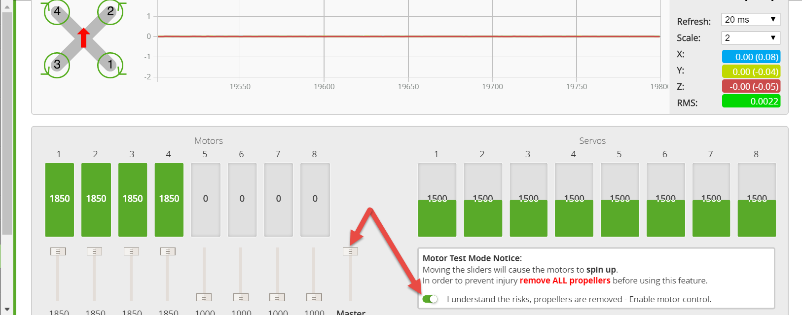
ESC calibration
- With the PROPS OFF!! and the LiPo Disconnected
- Go to the “motors” tab in CleanFlight, click the box at the bottom stating you understand the risk of moving props. Move the master slider all the way to the top, that will turn all motors to full throttle in CleanFlight. While the sliders are at full throttle you can now connect the battery, the motors will beep which means they have entered calibration mode. Now drag the master slider all the way down to the bottom to simulate a zero throttle signal, the motors will beep (musical tones) indicating calibration is completed successfully.
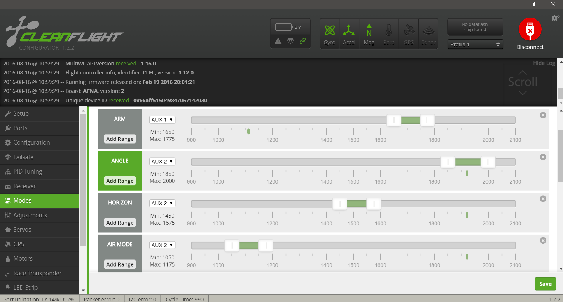
Flight Modes
The flight modes we will use are:
- Angle - Legacy Auto Level Flight Mode.
- Horizon - Auto Level Flight Mode.
- Air Mode - Alternative mixer and additional PID logic for more stable copter.
Please click here for detailed info on each flight mode.
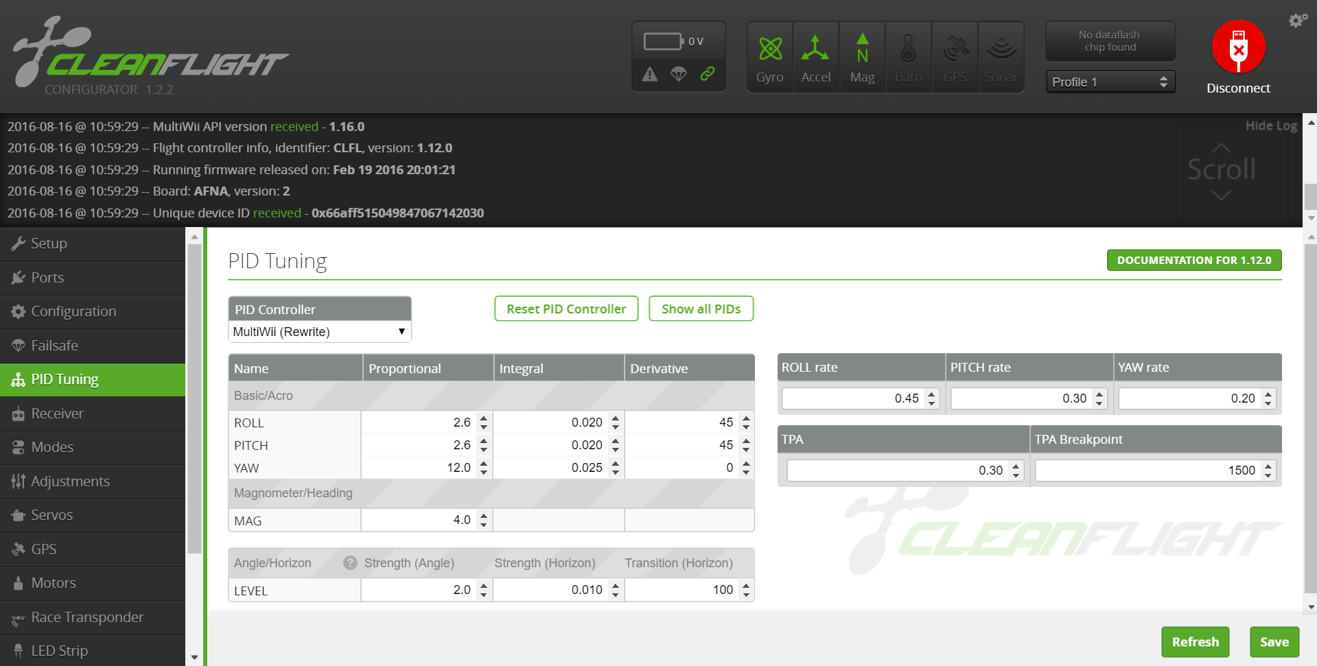
PID's
PID's are there own topic all together. I suggest starting with the default PID's in clean flight and making small adjustments from there. Click the link below to read more about PID's
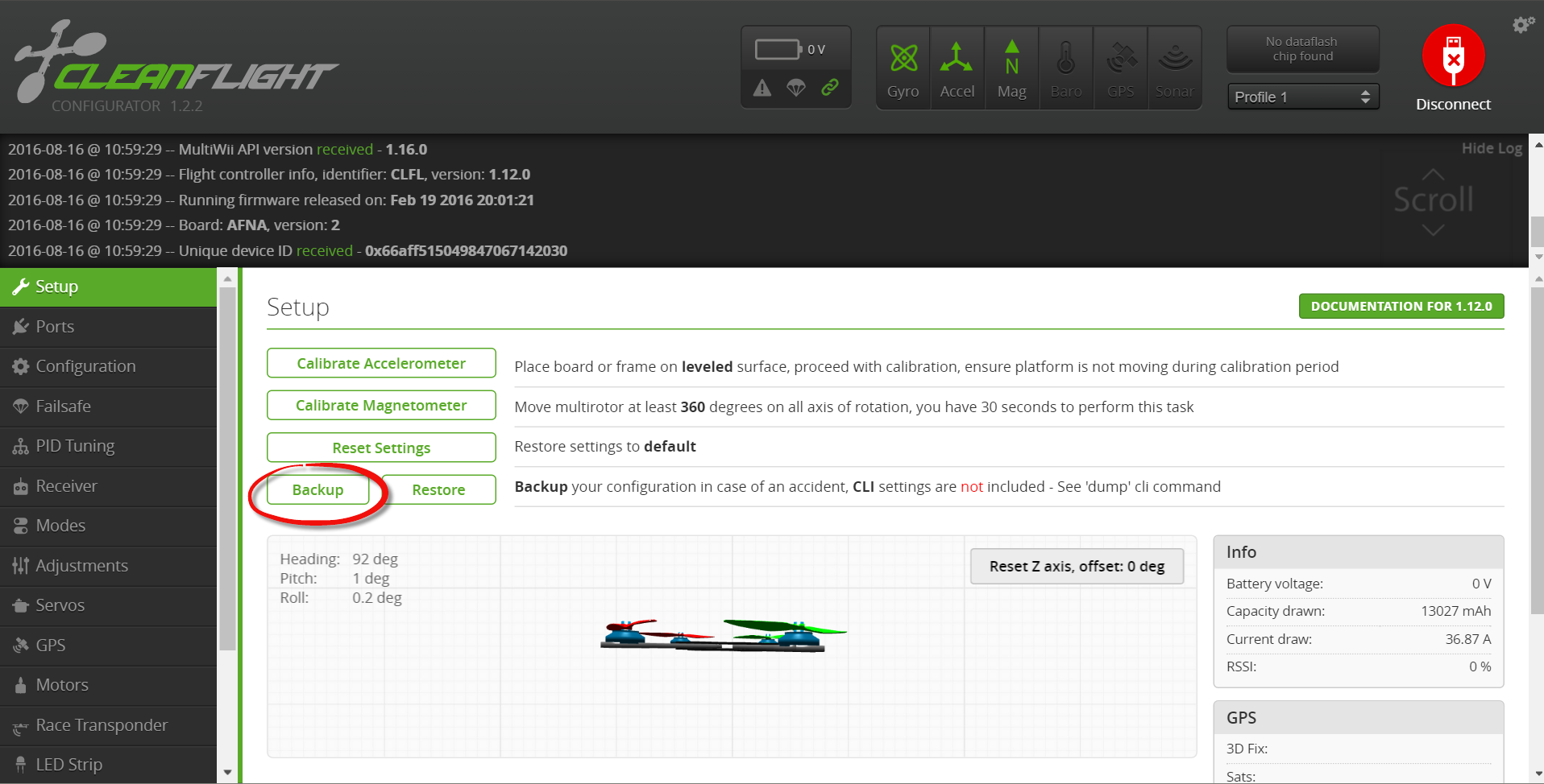
Backup your configuration
Finally back up your configuration from within CleanFlight
Downloads
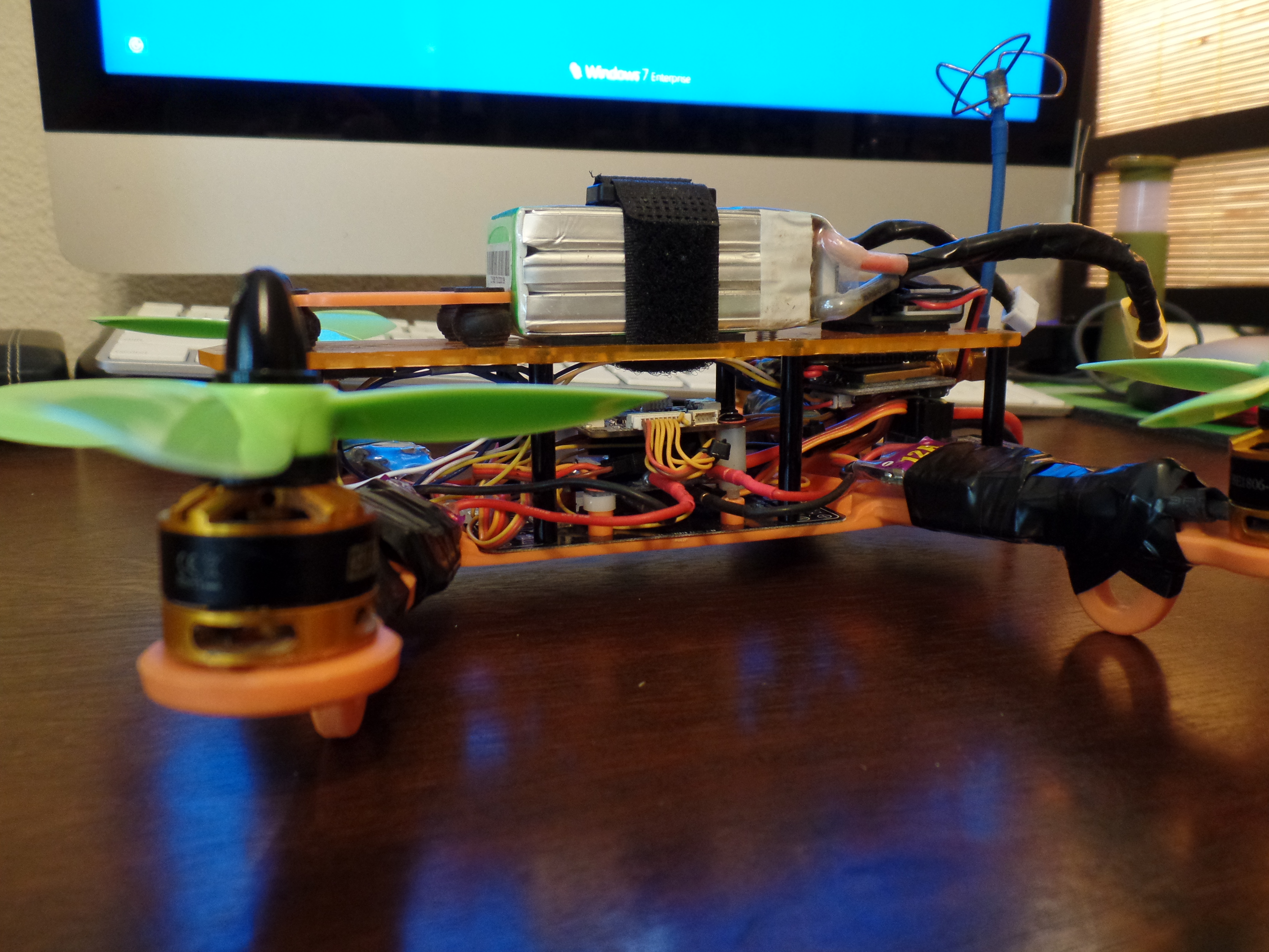
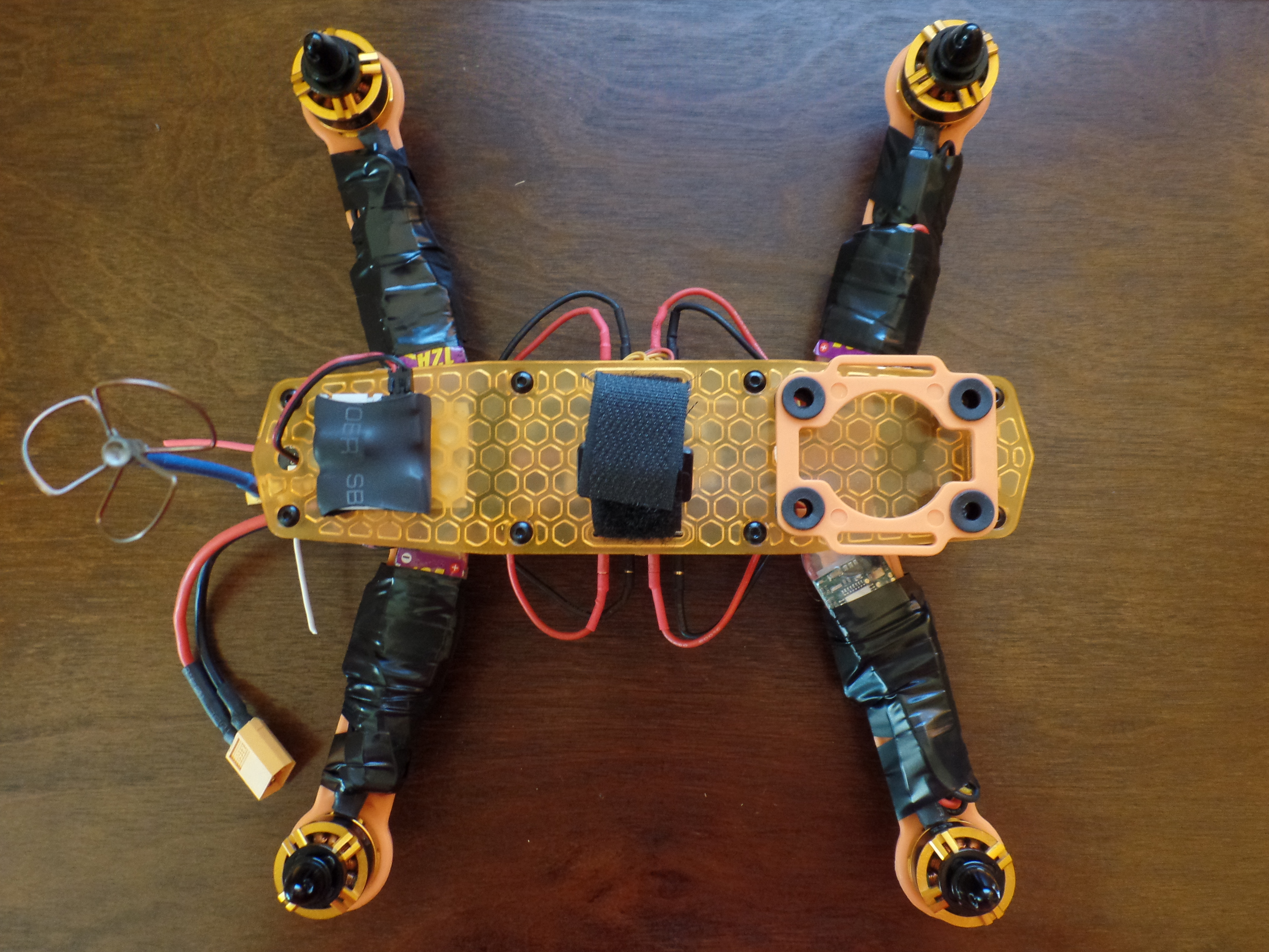
Fasten ESC's to the Quad Frame Arms
This is a good step to take your time on and do a little wire management. Your not dealing with a lot of space so you'll have to get creative with tucking wires in where you can. I used electrical tape to secure the ESC's to the quad arms and tucked the wires in with the ESC.
FPV Camera and Transmitter
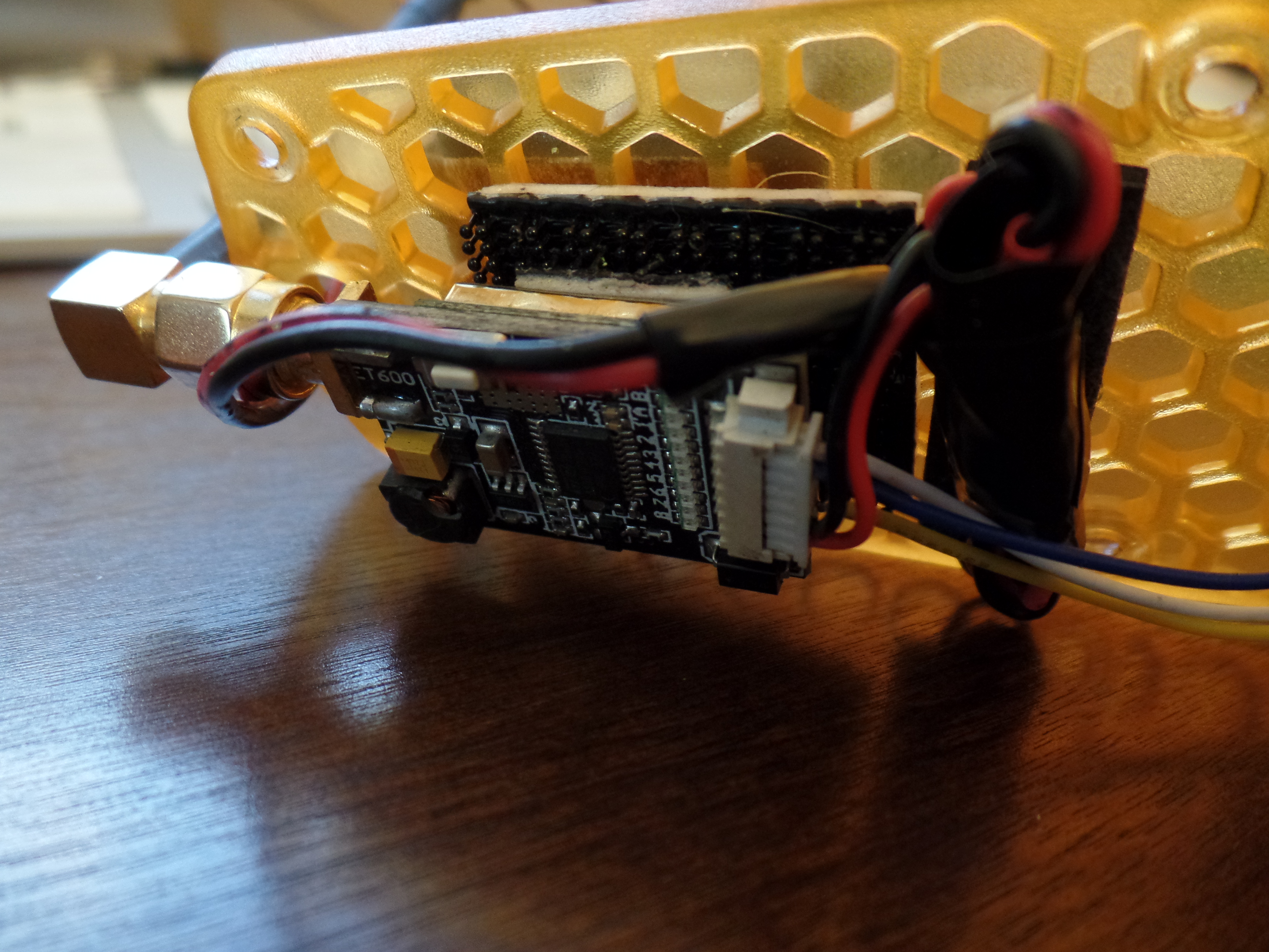
WARNING! Do not power on the transmitter without an antenna attached or you risk burning out the transmitter!
Since the radio signal between the transmitter and receiver for the flight controls operates at 2.4GHz I recommend going with an FPV setup in the 5.8GHz range to reduce the chances of interference between the two.
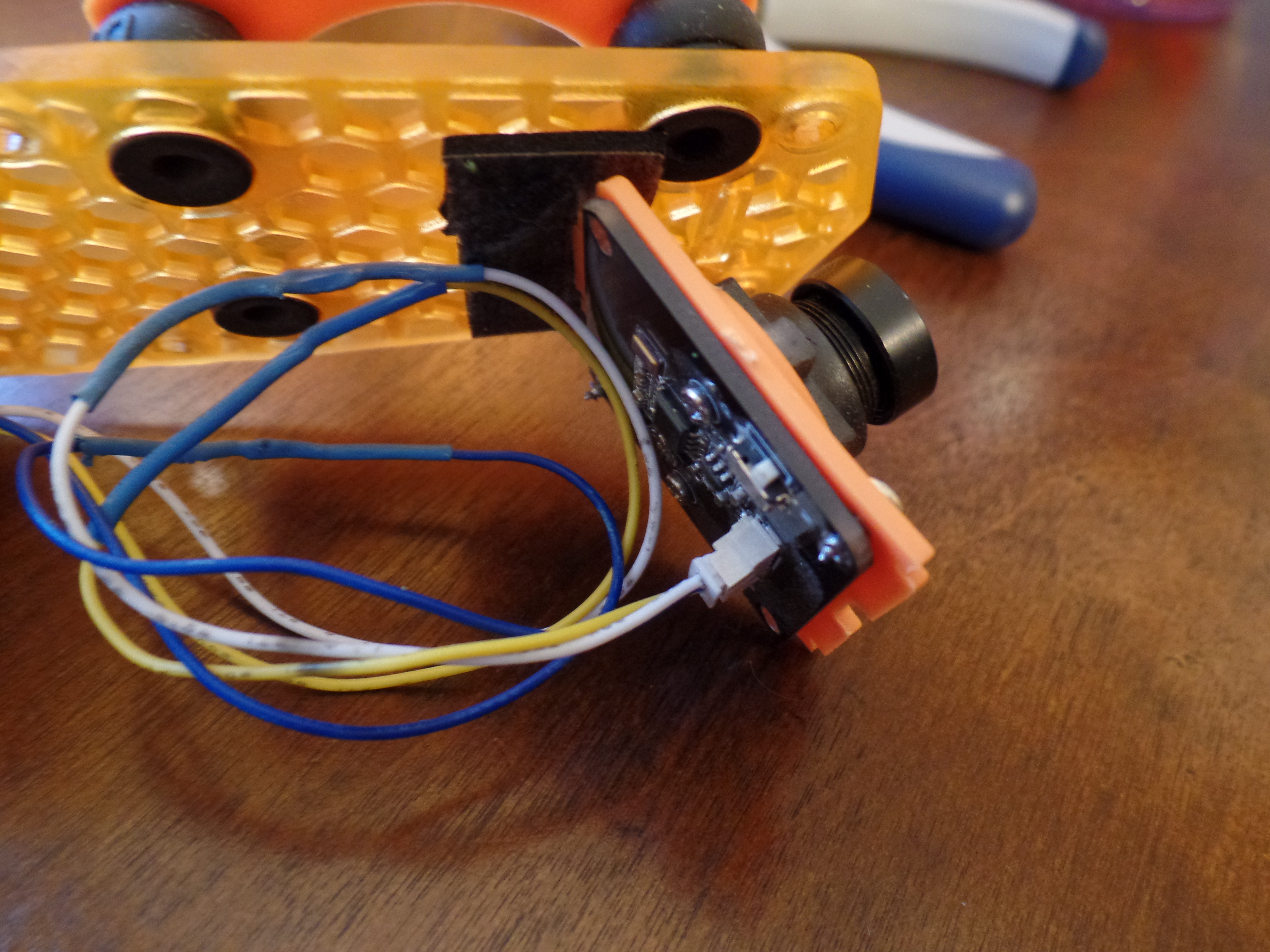
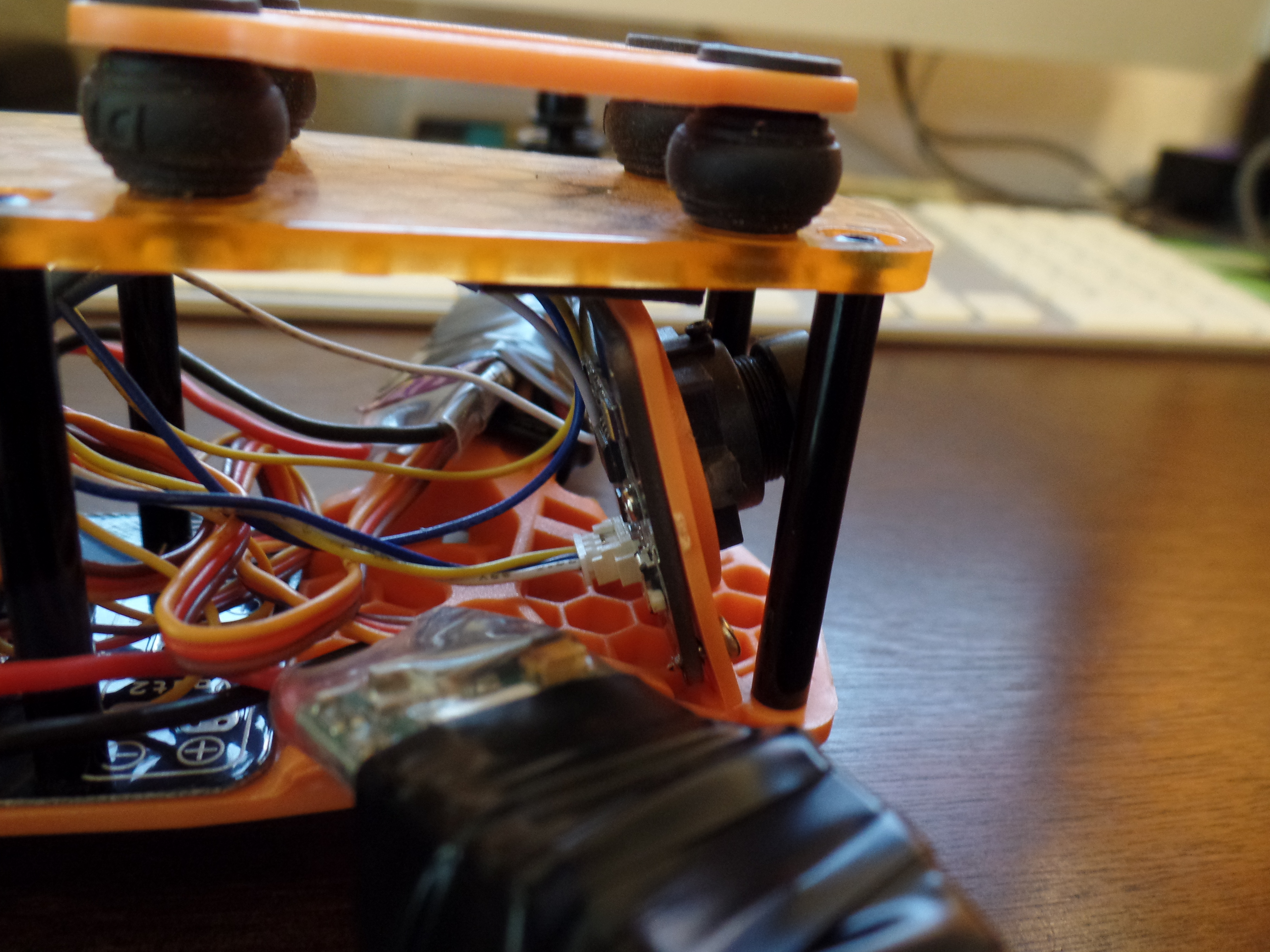
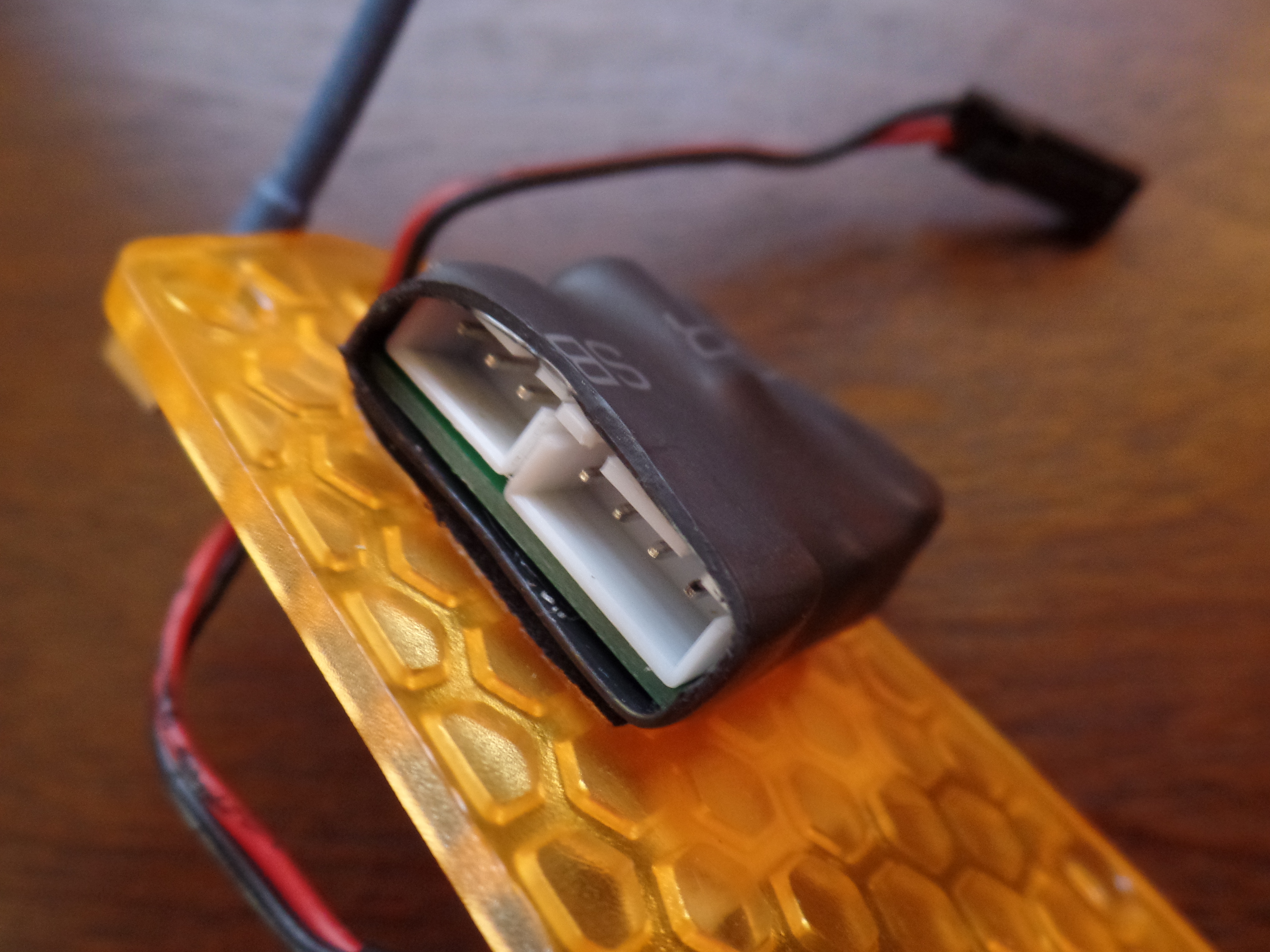
Attach the camera to the camera mount that comes with the frame kit. The camera mount installs at flat angle so this will present a problem when flying fast in a forward direction. I modified the angle of the camera by using 3M double sided tape as pictured.
The camera will plug in to the transmitter for power and video signal. To get power to the transmitter I am using a fatshark 5v UBEC that allows me to draw power through the balance lead on the LiPO.
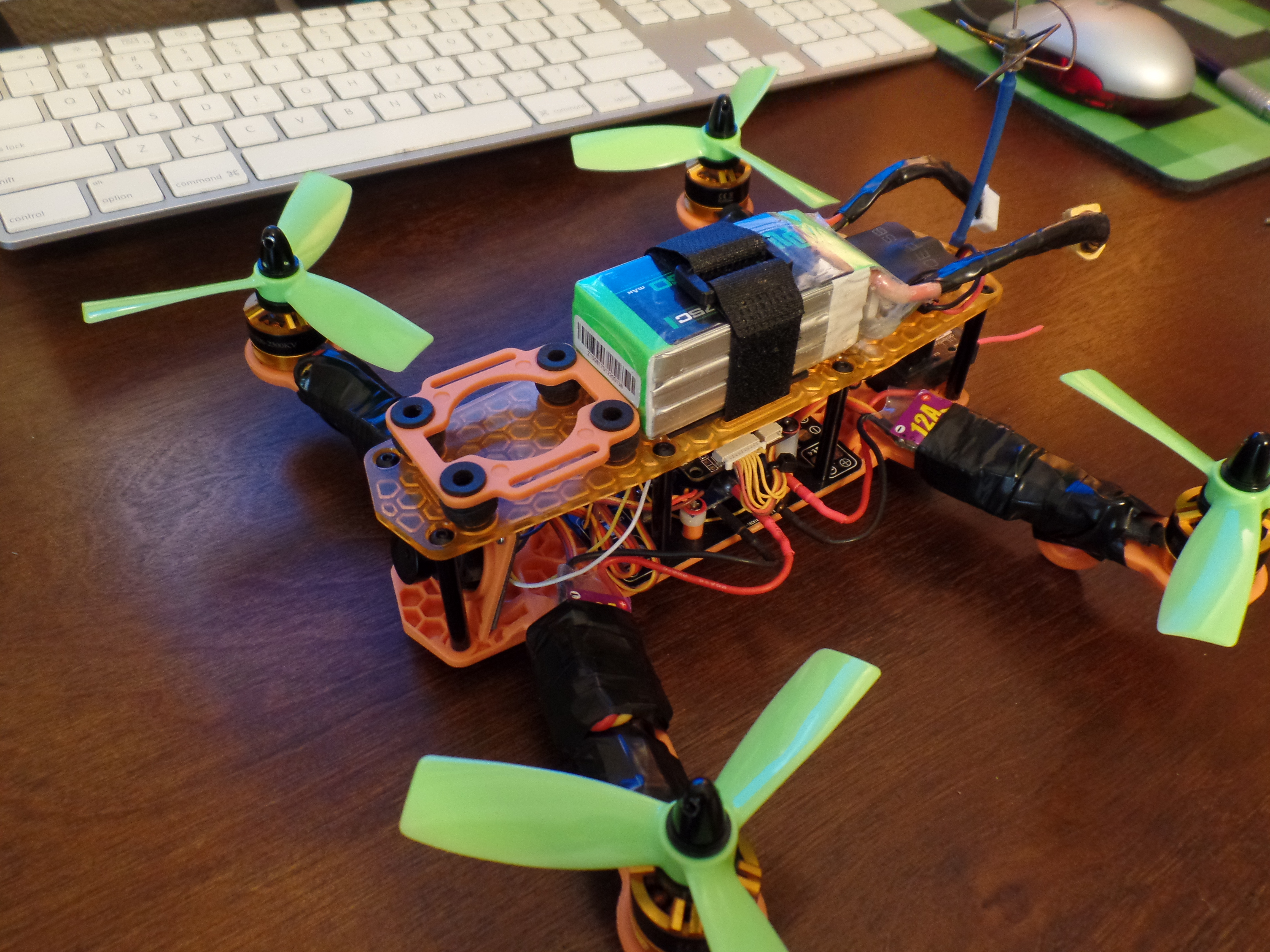
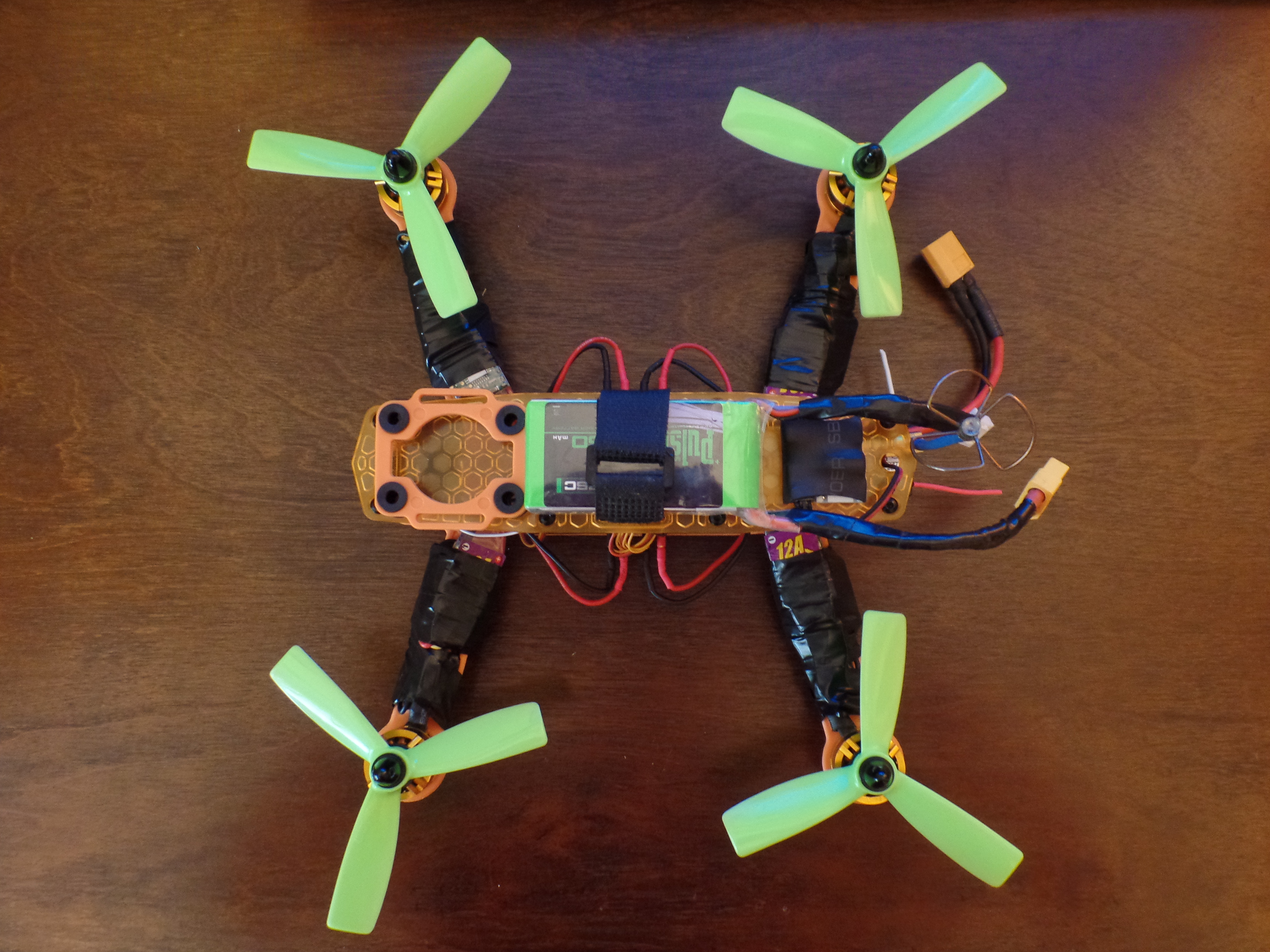
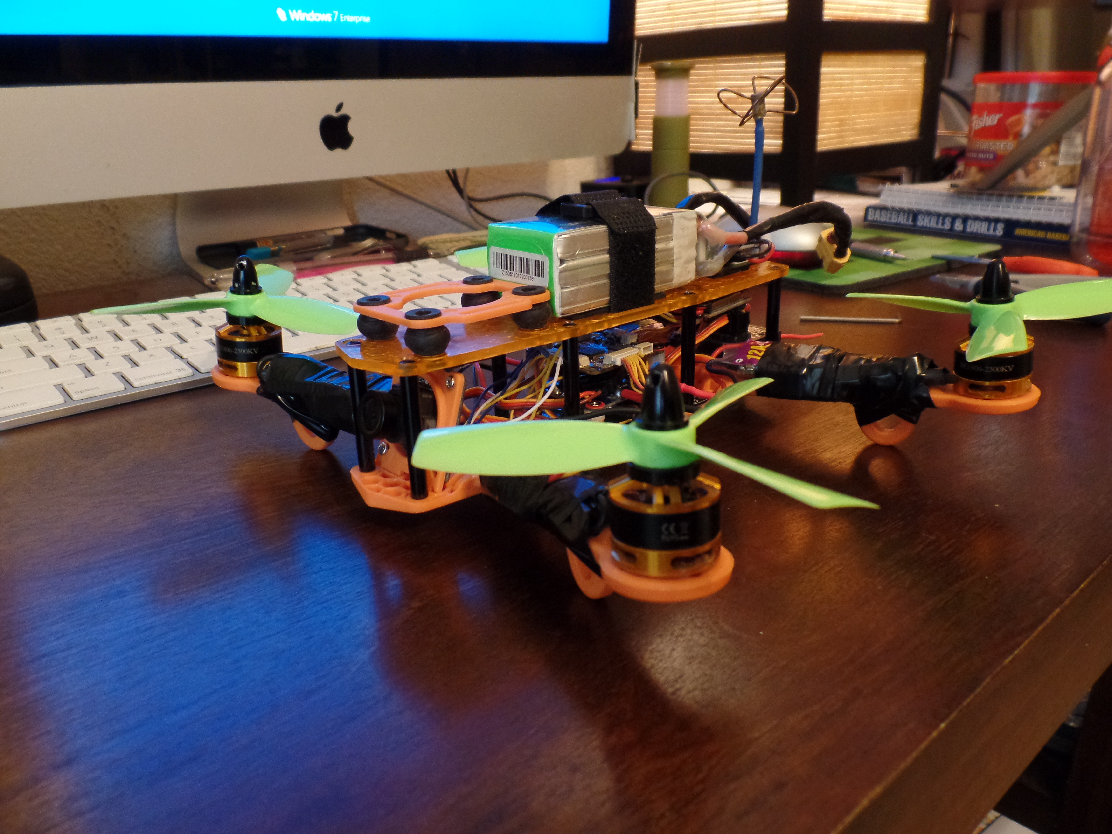
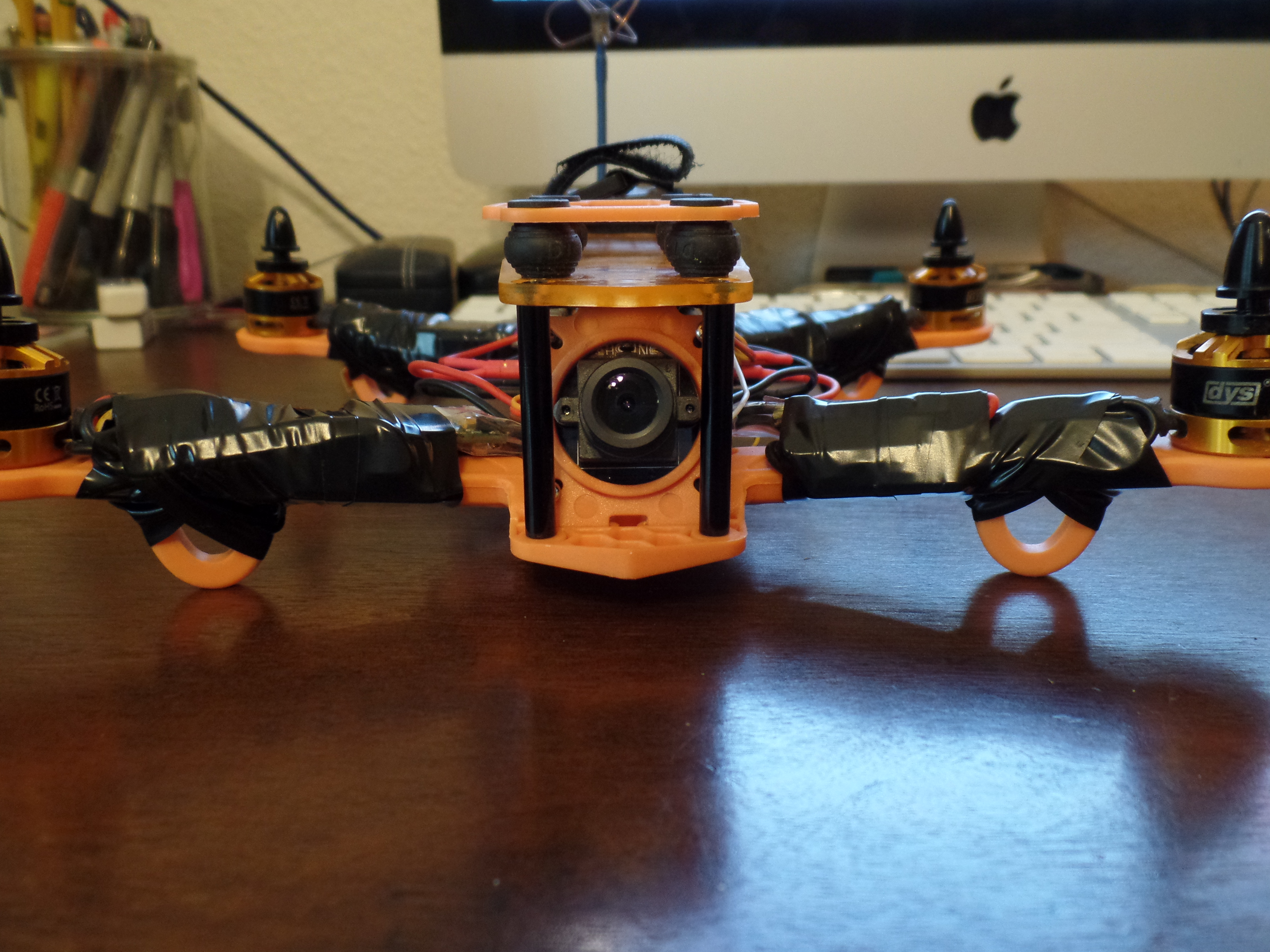
Mount the Top Plate of the Quad Frame and Attach the LiPo Battery

Materials and Tools
Materials
- Transmitter - Walkera DEVO 7 2.4GHz 7-channel Devention Transmitter - $49.99
- Receiver - Walkera 6CH 2.4Ghz RX601 Receiver - $15.99
- 250mm sized quad frame - $21.99
- Power Distribution Board (PDB) Usually included with the quad frame.
- Electronic Speed Controllers (ESC's) - $17.99 ea.
- EMAX Skyline32 Naze32 Acro Flight Controller with Compass Support Cleanflight Baseflight - $19.99
- DYS BE1806 1806 2300KV Brushless Motor 2-3S for Mini Multicopters - $9.99 ea.
- 10 Pairs Kingkong 4*4.5*3 4045 4 Inch 3-Blade Propellers CW CCW for FPV Racer - $6.86 per 10 pair.
- FPV Camera - Eachine 700TVL 600mw 1/3 CMOS FPV 148 Degree Camera w/32CH 5.8G 600mW FPV Transmission - $49.98
- 600mw video transmitter 5v UBEC for FPV transmitter power Clover Antennas - Anbee® FPV 5.8Ghz Circular Polarized Clover Leaf Antenna High Gain Aerial Set w/RP-SMA Plug - $10.98
- 3s/4s 1300mAh LiPO - 29.95 ea.
- Velcro battery strap - $6.99 5 pack
- XT60 connector - $2.88 M/F pair
- FPV Goggles - Fatshark Prededtor v2 $329 - There are much better goggles out now so shop around.
- DVR - Andoer RC732-DVR LCD FPV Monitor Built-in Battery and 32CH 5.8G Wireless Diversity Receiver - $116.70
Tools
- Soldering Iron
- Solder
- Electrical Tape
- Heat Shrink
- Alan Keys
- Wire Cutters
Consumables
- 3M double sided tape
- 3M dual Lock
- Electrical Tape
Pre-flight Practice


I reccomend starting off the 3s LiPo and practicing on a flight simulator like FPVFreerider which is a super cheap way to practice flying at only $4.99. You can start off in Horizon mode for self leveling and switch to acro mode when you are feeling more confident. There is a pretty good sticky on connecting your controller as well. There are several different flight environments to choose from like a parking garage, playground, open field, desert, and even an island. Once you have built up your skills try throwing in a 4s LiPo for a a whole new flight experience.