How to Build a Physical JK Flip Flop (Master Slave Configuration) and T Flip Flop
by square1a in Circuits > Electronics
2053 Views, 0 Favorites, 0 Comments
How to Build a Physical JK Flip Flop (Master Slave Configuration) and T Flip Flop

Table of Content
Explanations and theory (which include circuit diagrams. If you are experienced, all you need is the diagram to build the circuit)
Step 1: T flip flop
Step 2: basic JK flip flop
Step 3: JK Flip Flop (Master Slave Configuration)
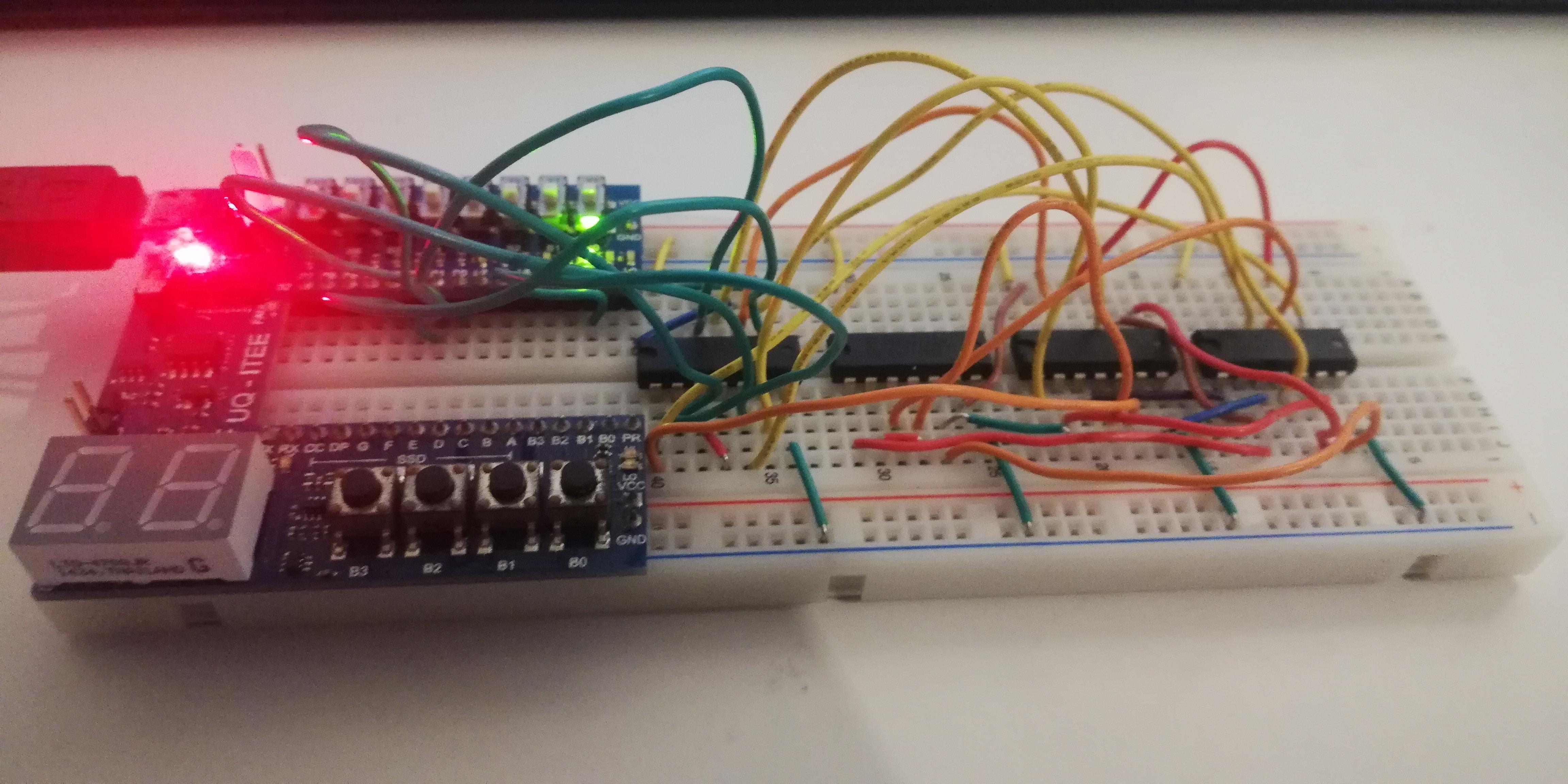
How I build it
Step 4: design circuit schematics
Step 5: insert components
Step 6: add wiring
Step 7: test the circuit
Supplies
General case:
- 6 AND logic gates
- 4 NOR gates
- 1 NOT gate
- plenty of jumper wires
- 3 switches for inputs
- 2 LED to represent outputs
- some batteries
- a breadboard
What I used:
- 6 AND logic gates (on 2 74HCT08 IC chips)
- 4 OR gates (on 1 74HCT32)
- 5 NOT gate (on 1 74HCT04)
- plenty of jumper wires
- An IO board that contains switches, LED's and power supply
- USB cable for the IO board
- a breadboard
T Flip Flop

image sourced from: https://www.electronics-tutorials.ws/sequential/conversion-of-flip-flops.html
The T stands for toggle. If the existing output is 0, the T flip flop turns it to a 1. If the existing output is 1, T flip flop turns to a 0.
You can use a JK flip flop as a T flip flop, by setting both J and K inputs as 1 (as shown in the diagram above). To learn about JK flip flop, go to Step 2 below.
You can also use a D flip flop as a T flip flop by feeding not Q output into D input (as shown in the diagram above). To learn about this, go to https://www.electronics-tutorials.ws/sequential/conversion-of-flip-flops.html.
Basic JK Flip Flop

image sourced from: https://www.electronics-tutorials.ws/sequential/conversion-of-flip-flops.html
The circuit schematics of a basic JK flip flop is above. It consists of a SR flip flop inside it. It has four modes: Set, Reset, Remember and Toggle.
Set: changes the output (Q) to 1
Reset: changes the output (Q) to 0
Remember: output is unchanged, and thus stored
Toggle: changes output from 1 to 0, or 0 to 1.
The output is updated at the moment when clock (CLK) changes from 0 to 1; since when clock = 0, the AND gates are locked at 0.
In the diagram above, Q and Not Q (Ǭ) outputs are connected to the inputs. This connection is only used for the toggle mode. Thus, the inputs of the toggle mode depends on existing output; and like any logic circuit, the output depends on the inputs. You have a feedback loop between inputs and outputs, creating an oscillation. This oscillation is very fast and thus difficult to observe, since the period of this oscillation is a long as the delays in logic gates (which are very very short).
There are two ways to prevent this feedback loop:
- have a clock ON pulse that is shorter than the period of the oscillation
- use the Master Slave configuration, which is discussed in the next step below
JK Flip Flop (master Slave Configuration)

The diagram above shows one SR flip flop (Master) feeding its outputs into the input of another SR (Slave). Being a JK flip flop, the outputs Q and Not Q (Ǭ) of slave are connected into the inputs J and K of master.
Both SR's are connected to the clock. The NOT gate between them means that at any time, on SR is in Toggle mode and other in Remember mode. Having one in Remember mode breaks the feedback loop problem discussed in the previous step above. Since the clock pulse oscillates, the two SR's constantly switch modes, allowing information to pass from master to slave.
The outputs of slave SR is updated at the moment when clock goes from 1 to 0.
Design the Circuit Schematic

You can draw the schematic by hand on paper.
Or you can use a free circuit simulator, like Logisim. Logisim tutorial for designing a JK flip flop is on the YouTube: https://youtu.be/oD6cXldjXiI. If you are new to Logisim, check out the description of the YouTube video for tips.
Insert Components and Power Connections

Component are inserted onto the breadboard as shown above.
Don't forget to connect the logic gate chips to VCC and ground.
Add Wirings

Wire up the circuit according to the schematics.
Test the Circuit
)
The circuit worked as I expect in all four states: Set, Memory, Reset and Toggle