How To: Create an Intensity Lamp Using an Arduino
by MrShahmeerKhan in Circuits > Arduino
587 Views, 5 Favorites, 0 Comments
How To: Create an Intensity Lamp Using an Arduino
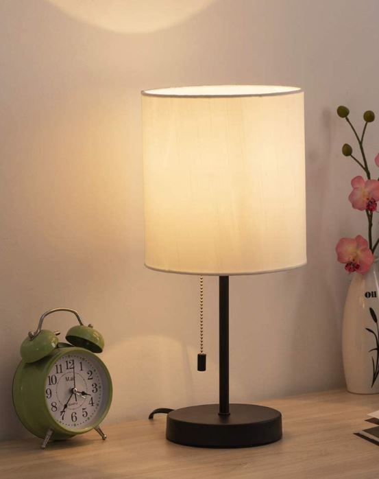
Wouldn't it be cool if you had a lamp that can adjust its brightness depending on if the room is dark? Maybe you're reading a good book and you notice it is getting dark and you're too lazy to walk across your room to turn the lamp on.
Well, this project will show you how to create a lamp that will change in brightness depending on the amount of light in a room. This project is not too difficult to make; as it only requires a few materials and a general knowledge of electrical engineering.
Well let's get to it!
Supplies
- Solderless Bread Board
- 40W LED Light Bulb (If you don't have one lying around)
- Lamp holder with exposed positive/negative terminals (Make sure it can work with your light bulb check manufacturing websites for more details)
- GL5516 LDR Photo Resistors
- Arduino Uno REV3 (You can buy kits that will have most of this stuff from Amazon)
- 1x 1k Ohms Resistor
- Power Supply (PSU) (We will use 9v battery as a demonstration, you might need something stronger)
- 9v connector (optional only if using a 9v)
- 6 Pin relay module
- Assortment of solid jumper wires (different colours are optional)
Understanding What a Relay Is
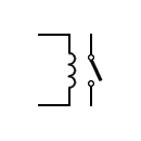
A relay is a small component that consists of a magnetic coil that has its own magnetic field when current is passing through it. When a relay is activated, it can attract a switch on a completely different circuit, which creates a complete path and allows the electrons to flow smoothly. A relay is useful in this project because since the Arduino is a low powered component and can only provide 5 volts, we need a way for the power supply (PSU) to receive a signal from the Arduino without it destroying the micro controller itself. This video is an excellent example of how a relay works.
How Does a Breadboard Work?
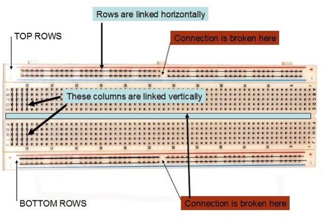
Since the breadboard is going to be the foundation of our entire circuit, it is a good idea that we understand how it works. A bread board consists of a bunch of holes, where many of them are connected. We can place electronic components into these holes and create circuits. See the diagram above for an example. Often times, the side railings that are connected horizontally will be used as ground and power in order to keep things organized. We will do the same for this project.
Making the Circuit (Power and Ground)
Okay let's get building, shall we?
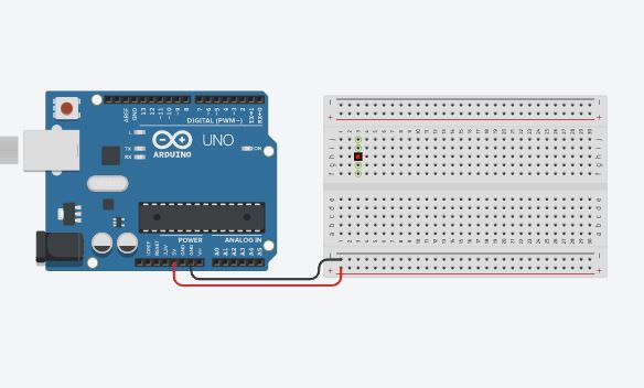
I have attached a bunch of pictures of the circuit diagram and schematic to help you while you build.
What we want to do first is make sure our Arduino is connected to a power supply so it can turn on. Once that is done, we can start setting up our breadboard. First attach a wire between the GND pin on the Arduino and place it into the horizontal railing on the side. This will be our ground line. Then, attach the 5V pin on the Arduino and place that adjacent to the ground railing. This will be our power line.
Making the Circuit (placing Components)
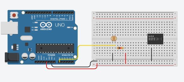
Now let's place the photoresistor, the 1k Ohm resistor, and the relay onto our circuit. Place the photoresistor anywhere on your breadboard, but make sure its two legs are on two separate vertical rails. Then attach a wire from the left leg into the ground railing. Then attach another wire on the right leg, going into the A0 (or analog 0) pin on the Arduino.
On that same railing, attach the 1k Ohm and place the other leg of the resistor anywhere on the breadboard (preferably close by). The leg of the resistor that is not connected to anything, attach it to a power railing by using a wire.
Finally, place the relay between the gap on the breadboard. Make sure pin NO and the coil pin are on the left side and the common pin is on the right side.
Making the Circuit (attaching the Lightbulb)
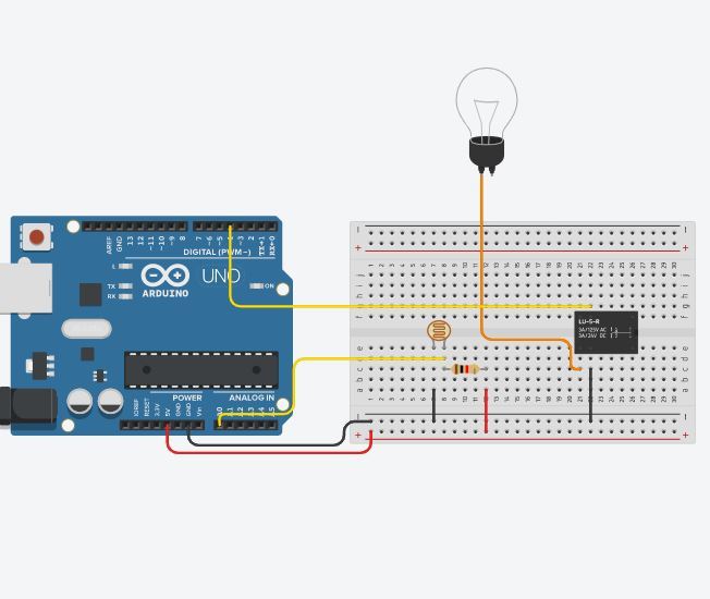
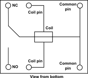
Now let's attach the light bulb to the relay. Connect terminal 1 to the relay with a wire. Attach it to the pin that is on the left hand side of the ground wire (the NO pin). If you are doing this project with actual tools and not on a program, use the lamp holder with the exposed negative terminal and connect that into the relay. Then use the pin that is directly across the relay (coil pin), and attach that to pin 4 on the Arduino. This might be a bit confusing so make sure you see the breadboard diagram and the pin layout.
Making the Circuit (attaching the Battery)
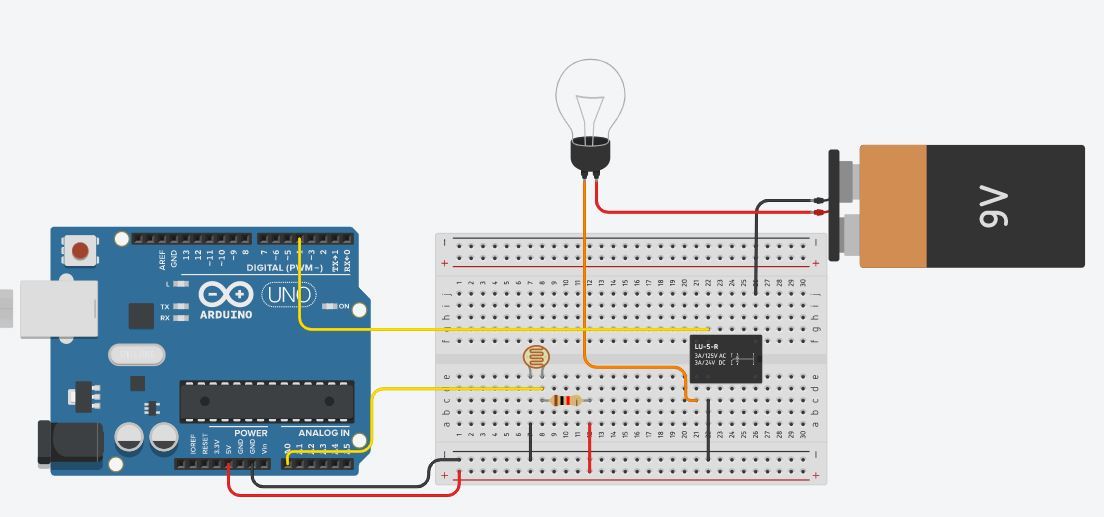
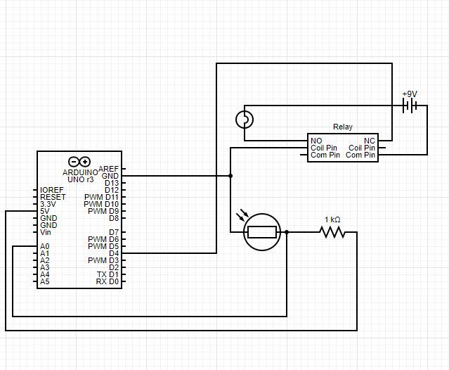
Okay, this is the final step in the circuit design. Attach the battery onto the 9v connector and place the ground wire onto the common pin on the relay and the power wire on the cathode terminal of the light bulb.
Coding
On a computer, there should be a program where you can code the Arduino. I have attached a link that will lead you to where you can download it. The code is pretty simple and is not too long.
void setup()
{
pinMode(A0, INPUT);
Serial.begin(9600);
pinMode(4, OUTPUT);
}
void loop()
{
Serial.println(analogRead(A0));
if (analogRead(A0) > 500) {
digitalWrite(4, LOW); } else {
digitalWrite(4, HIGH);
}
delay(10);
}