How Can You Create Your Own First IoT Project in the Fastest and Easiest Way Possible?
by earldanielph in Circuits > Electronics
706 Views, 7 Favorites, 0 Comments
How Can You Create Your Own First IoT Project in the Fastest and Easiest Way Possible?
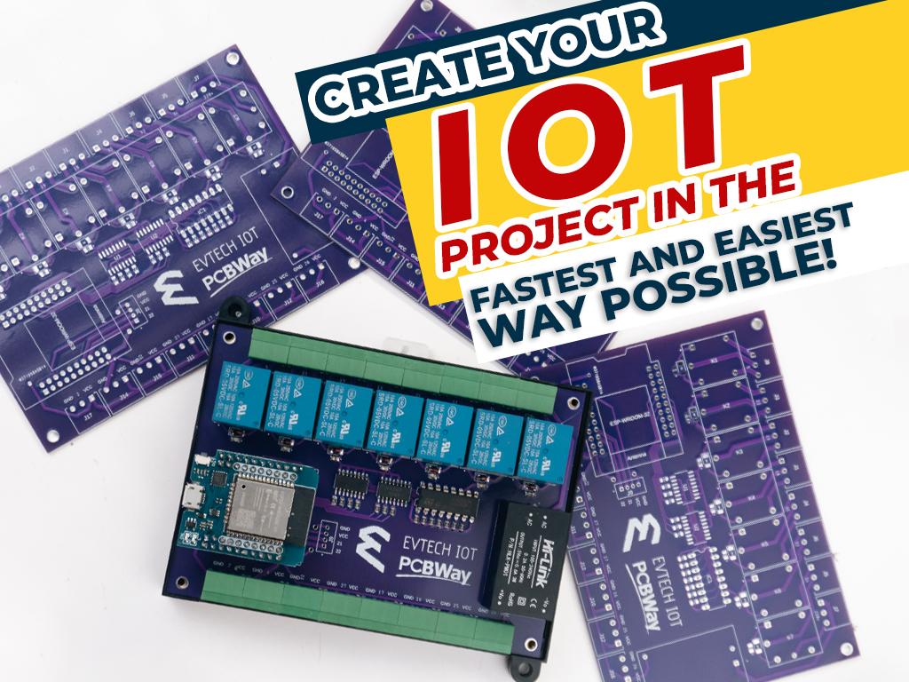
Today, I am going to teach you how to create your own first IoT project in the fastest and easiest way possible!
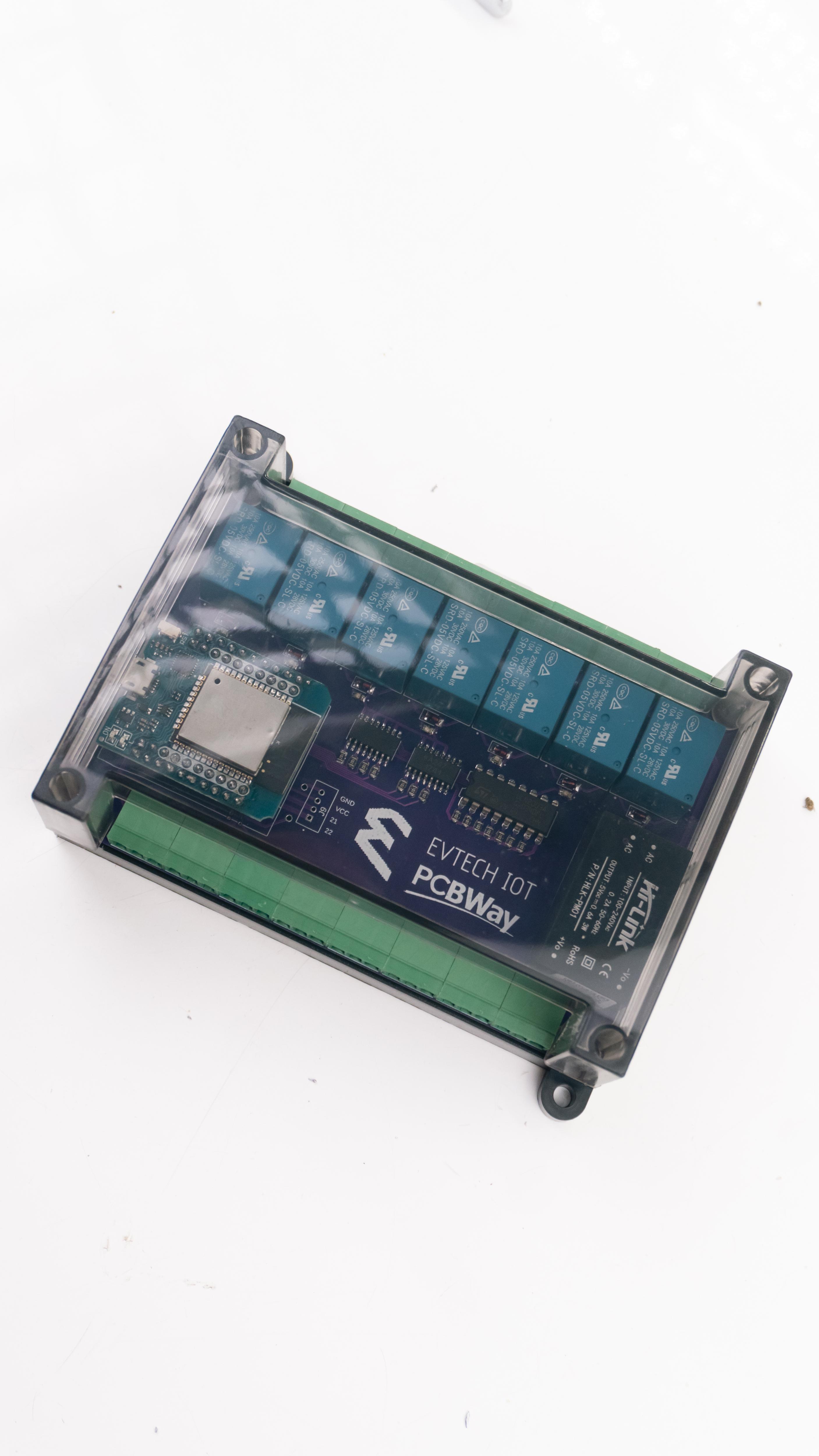
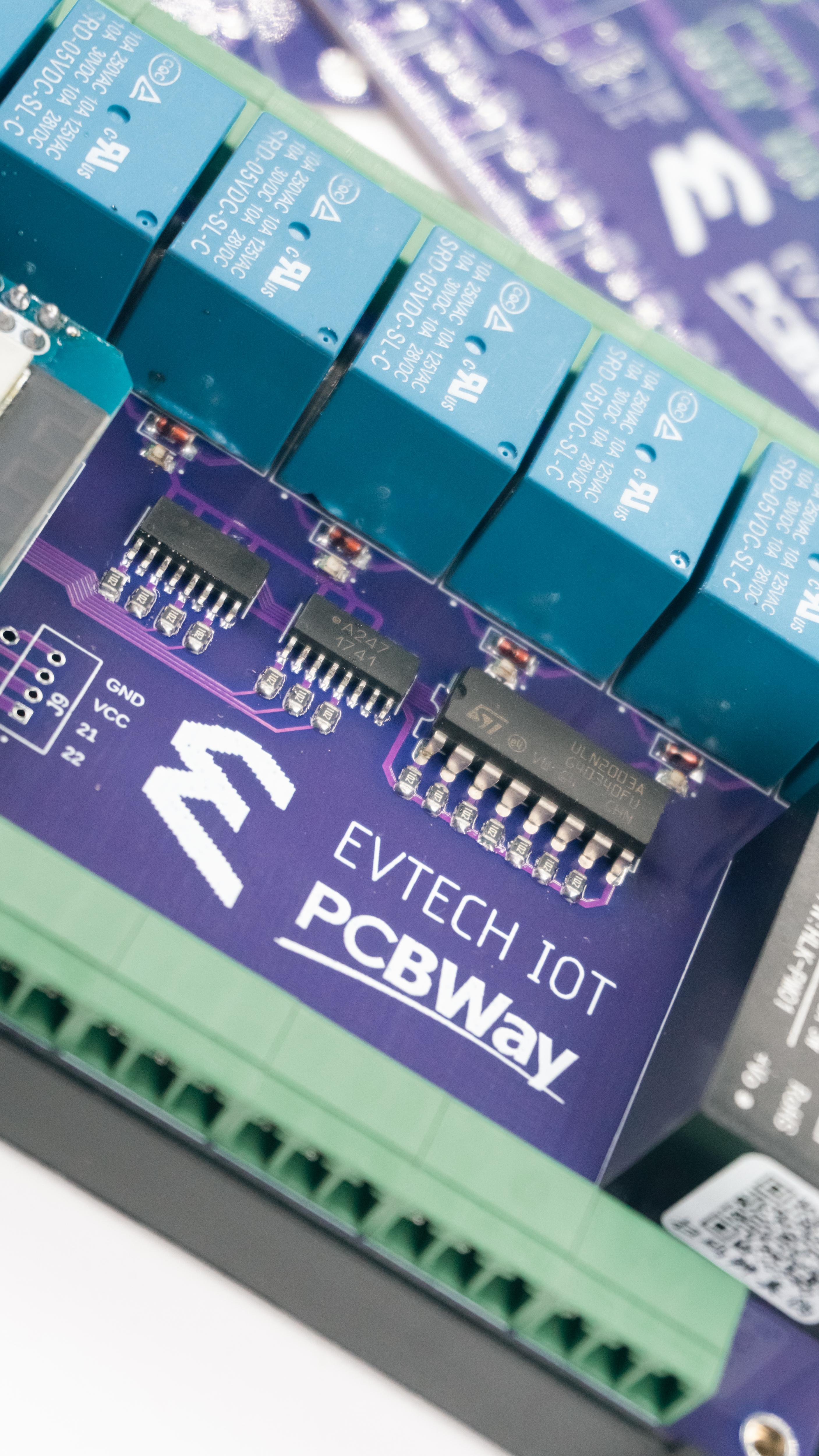
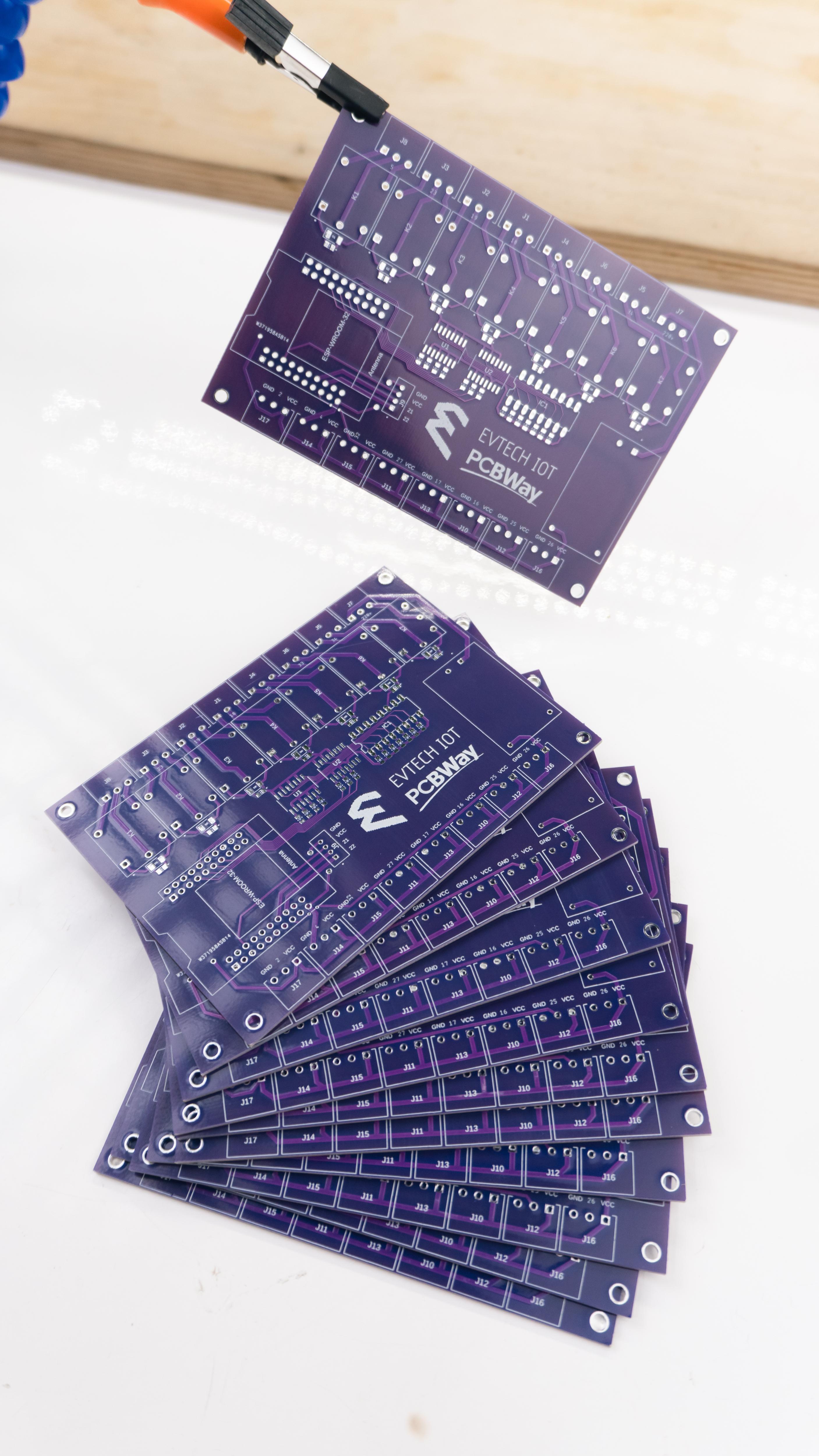
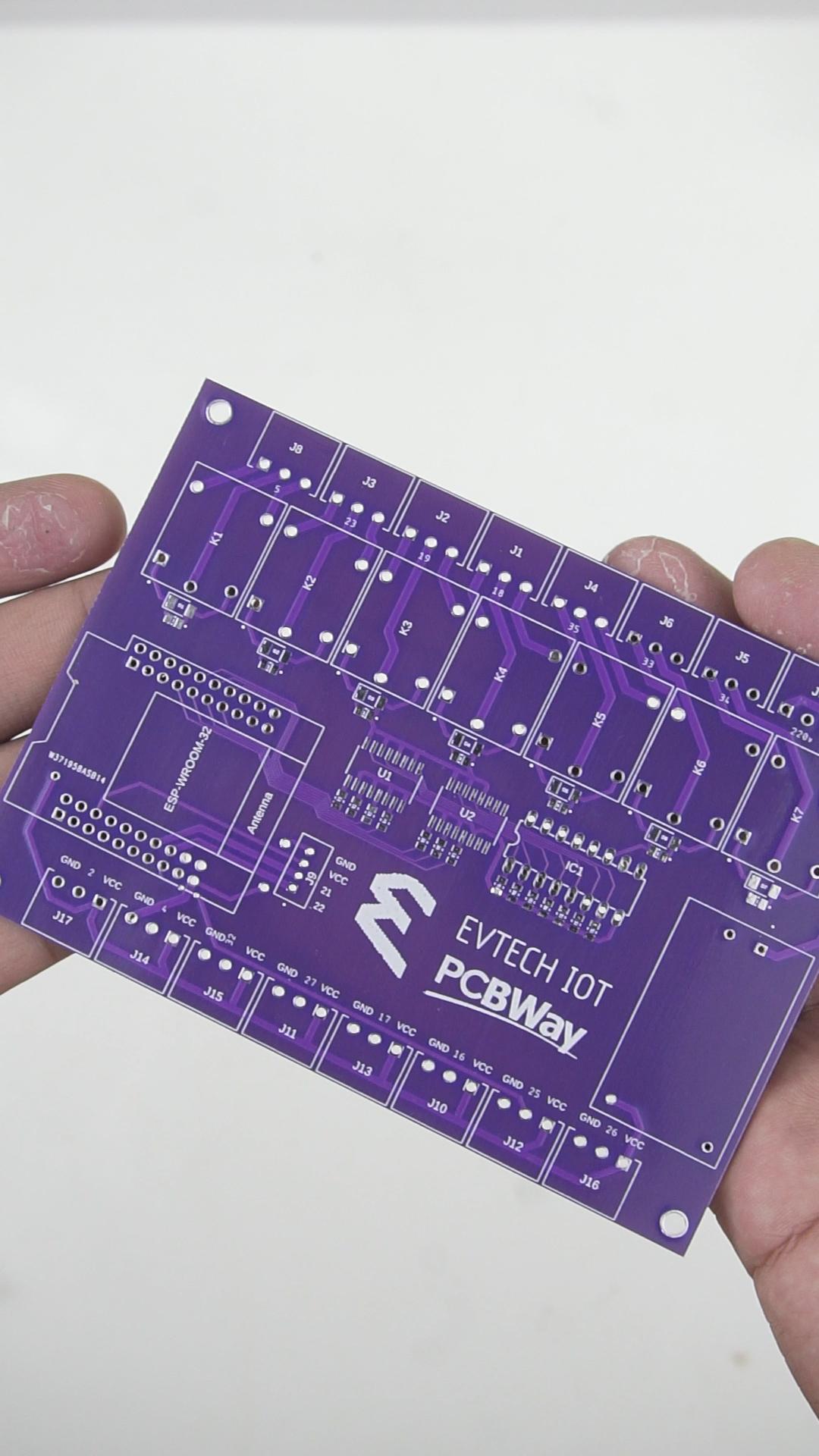
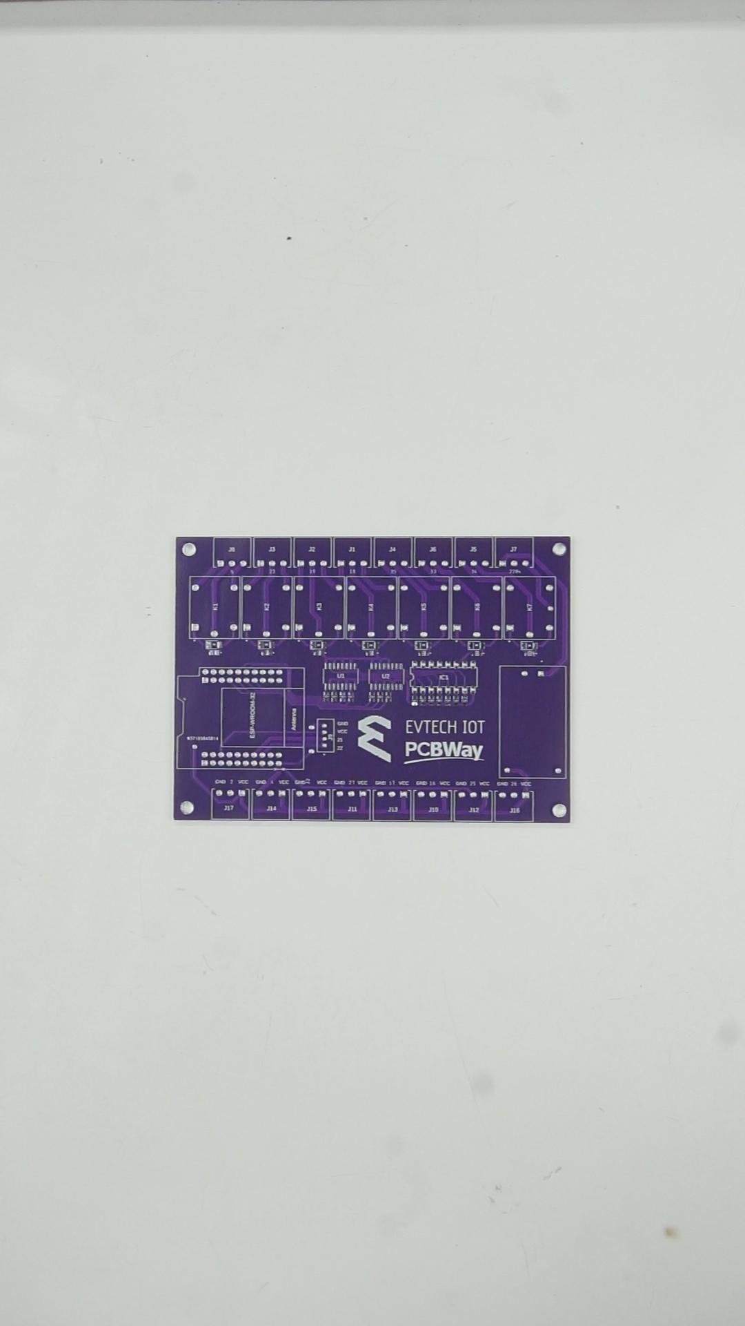
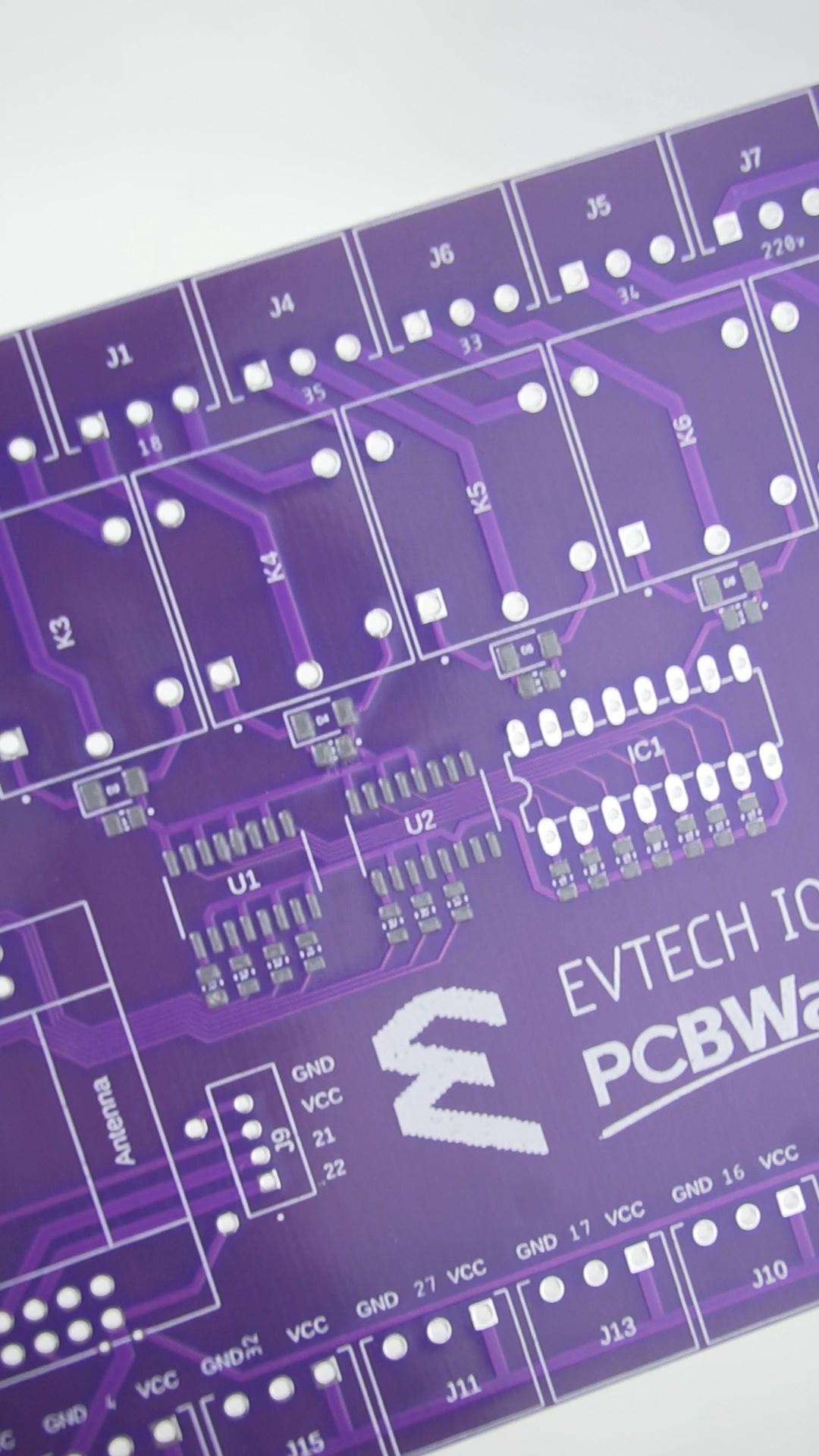
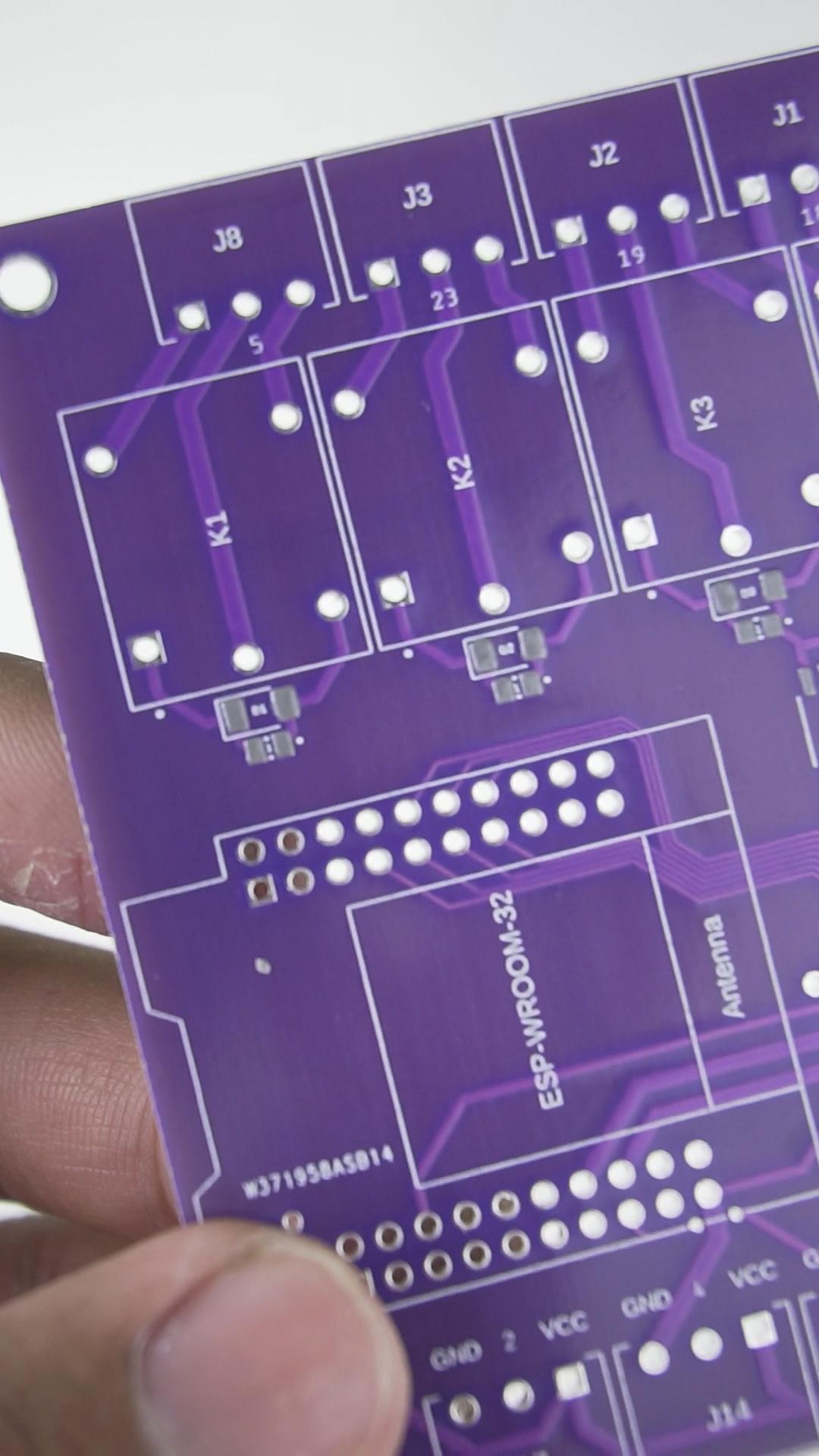
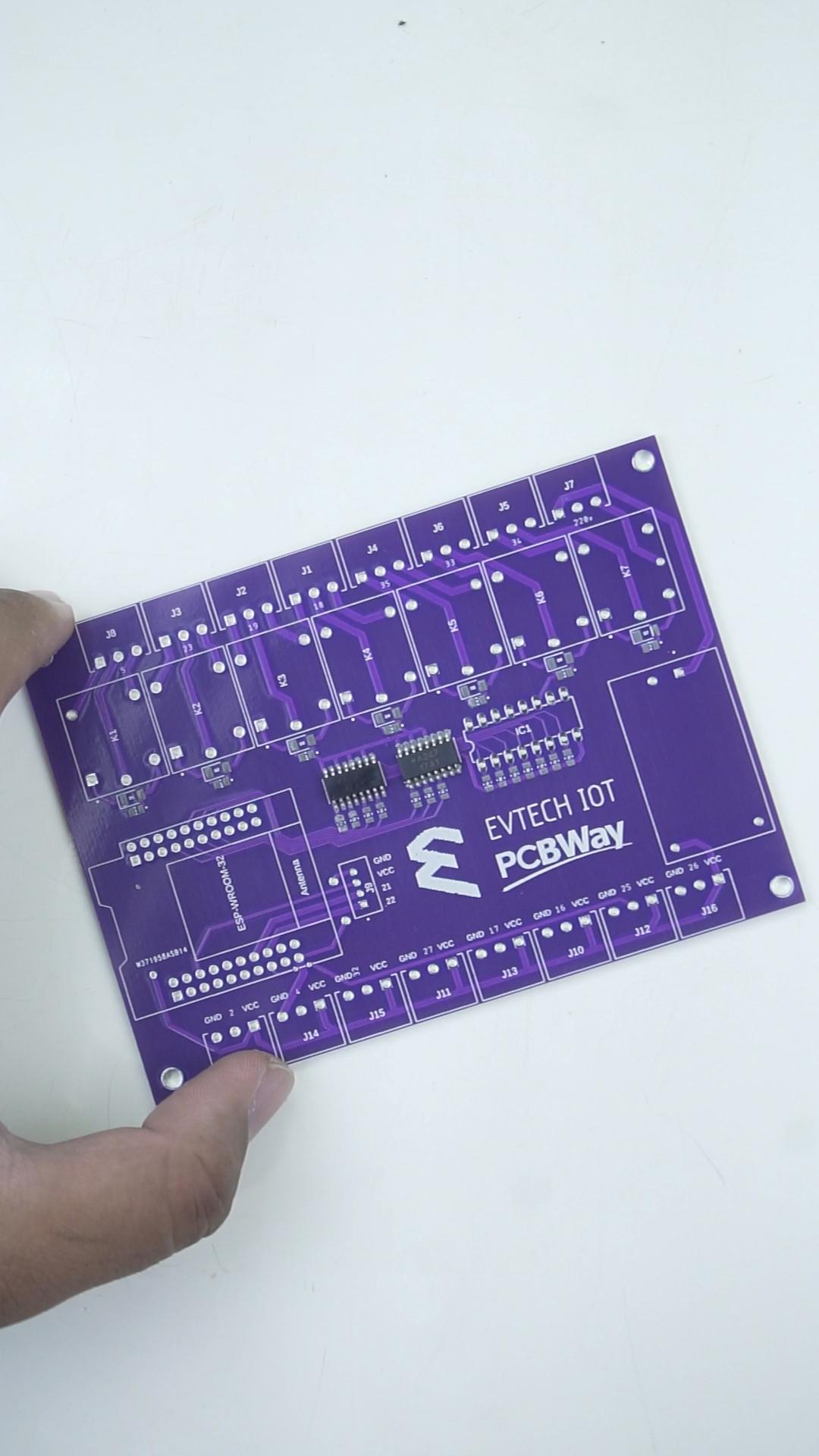
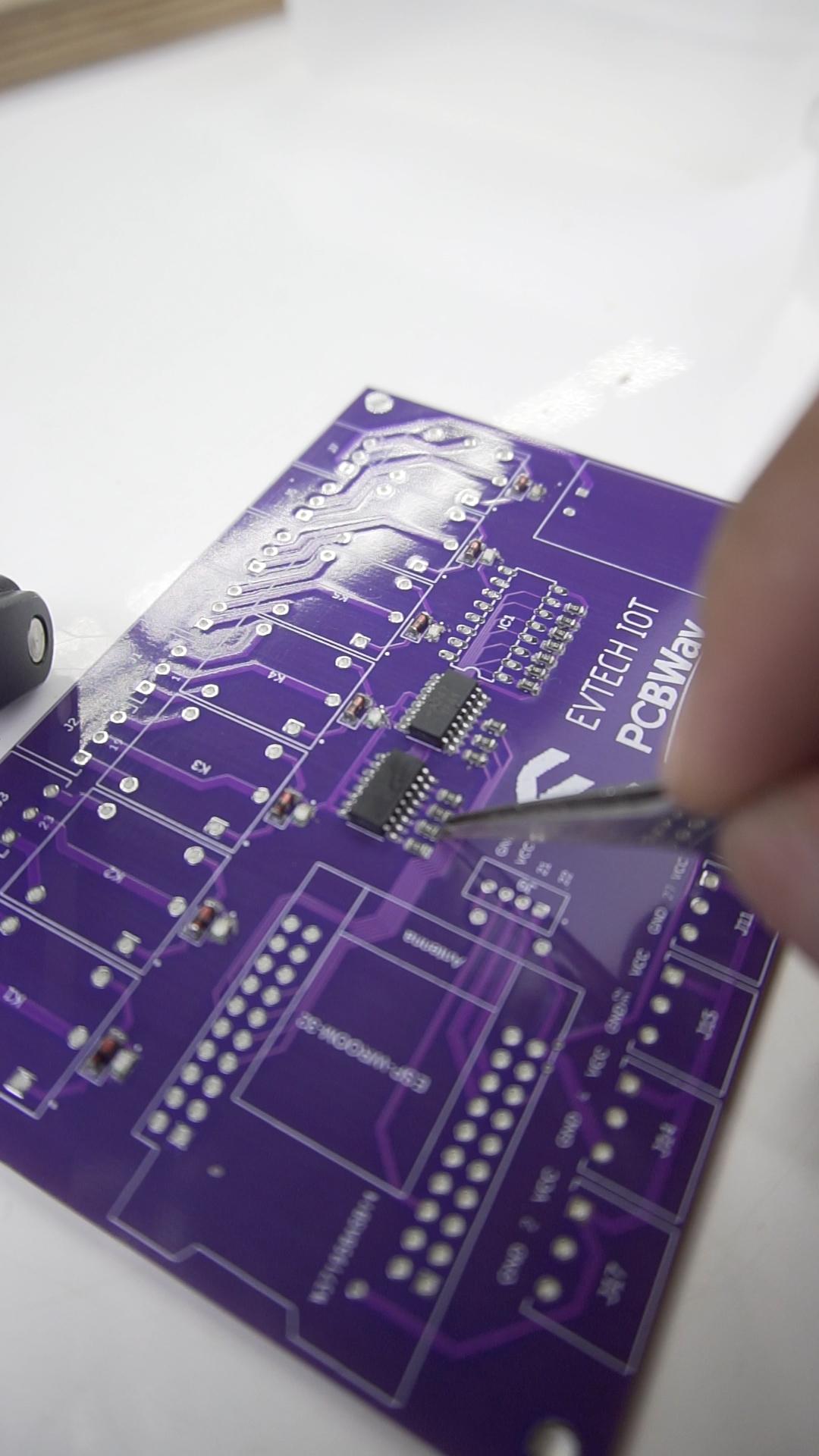
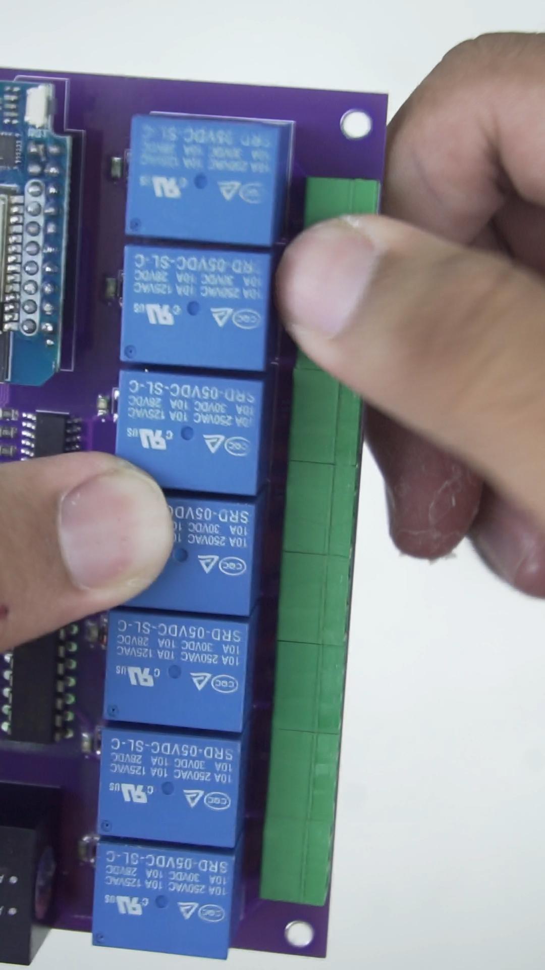
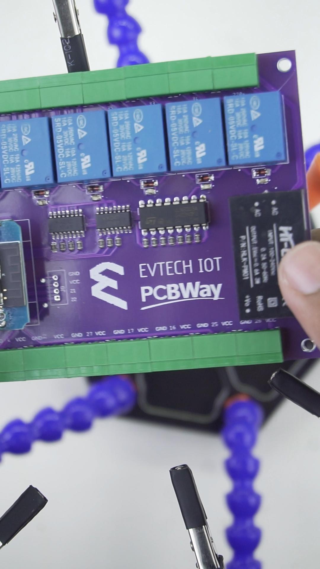
This is the Evtech IOT Universal Controller. This project can control up to seven electronic devices and features eight input pins to connect sensors. You can control your electronic devices using your mobile phone or your PC. I also added a feature that allows me to integrate an i2c LCD with it.
The Problem:
I remember when I started learning IoT (Internet of Things) a few years ago, I was limited in resources on how to create my first IoT project. I was only able to learn it with the help of my uncle. Today, there are plenty of good tutorials on how to create one. However, the problem is that many of those tutorials skip important details. That's why today, I have created a detailed tutorial that even a primary student can follow!
So what are we waiting for? Let's get ride into it!
VIDEO TUTORIAL:
Supplies
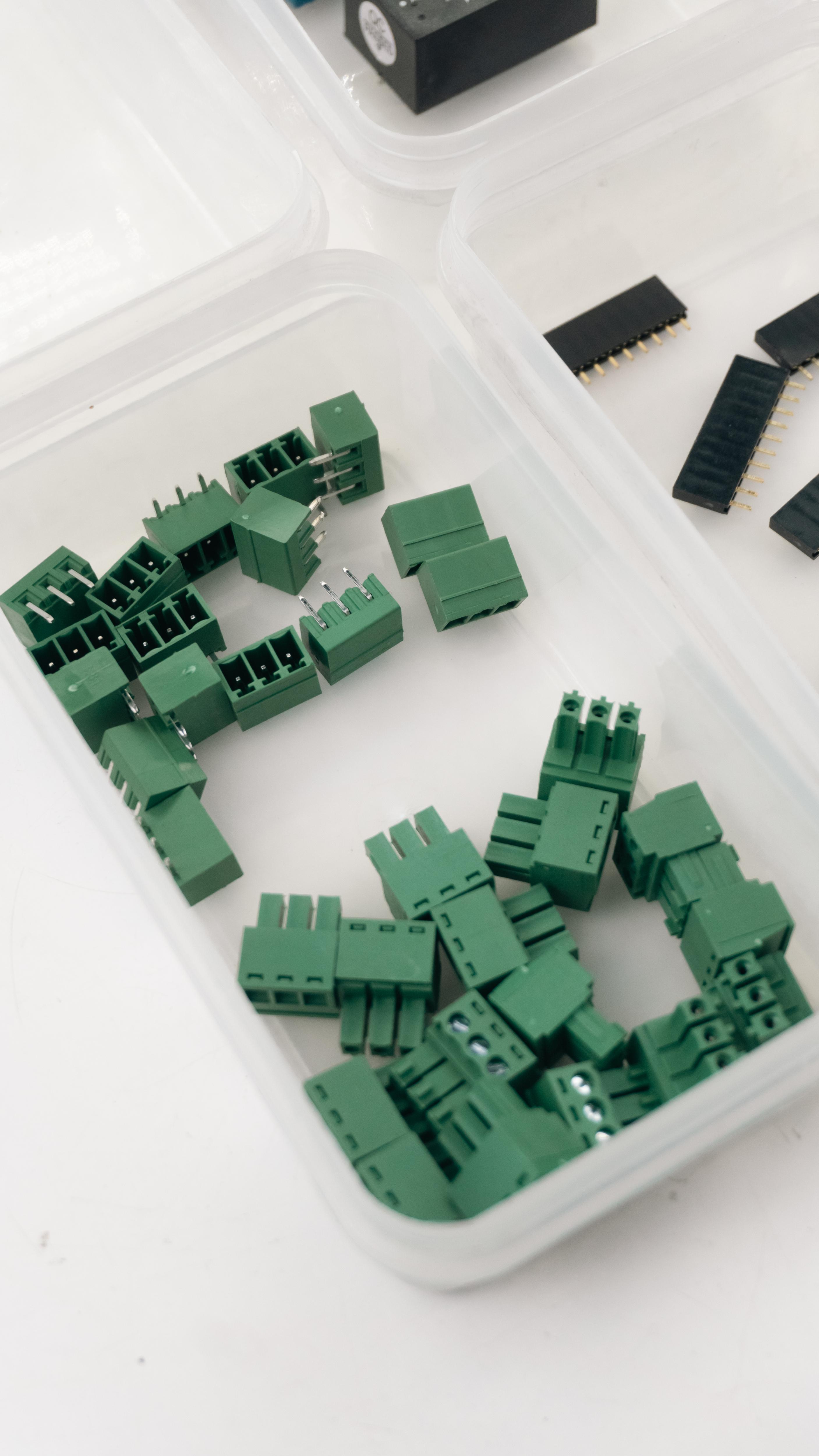
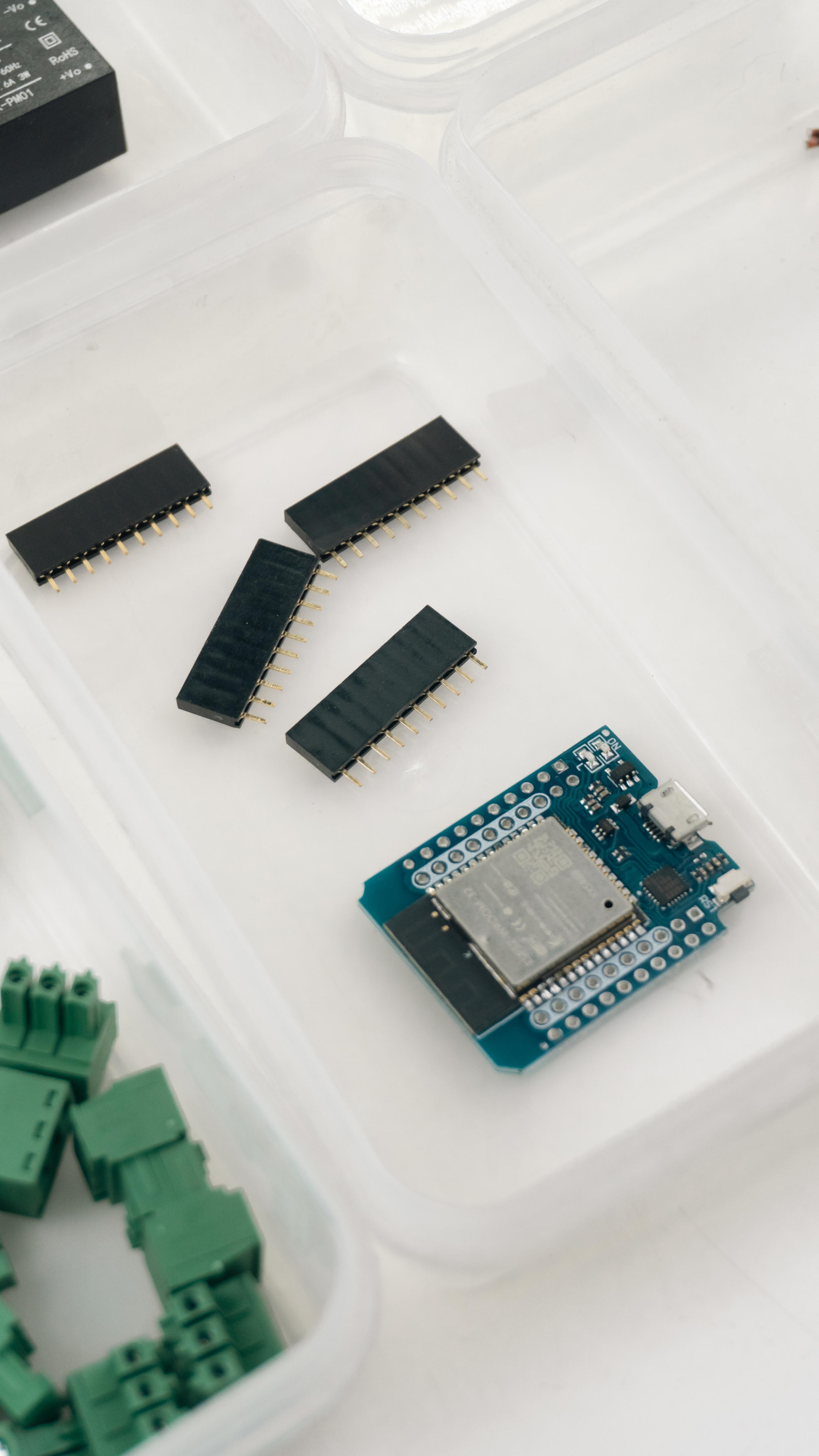
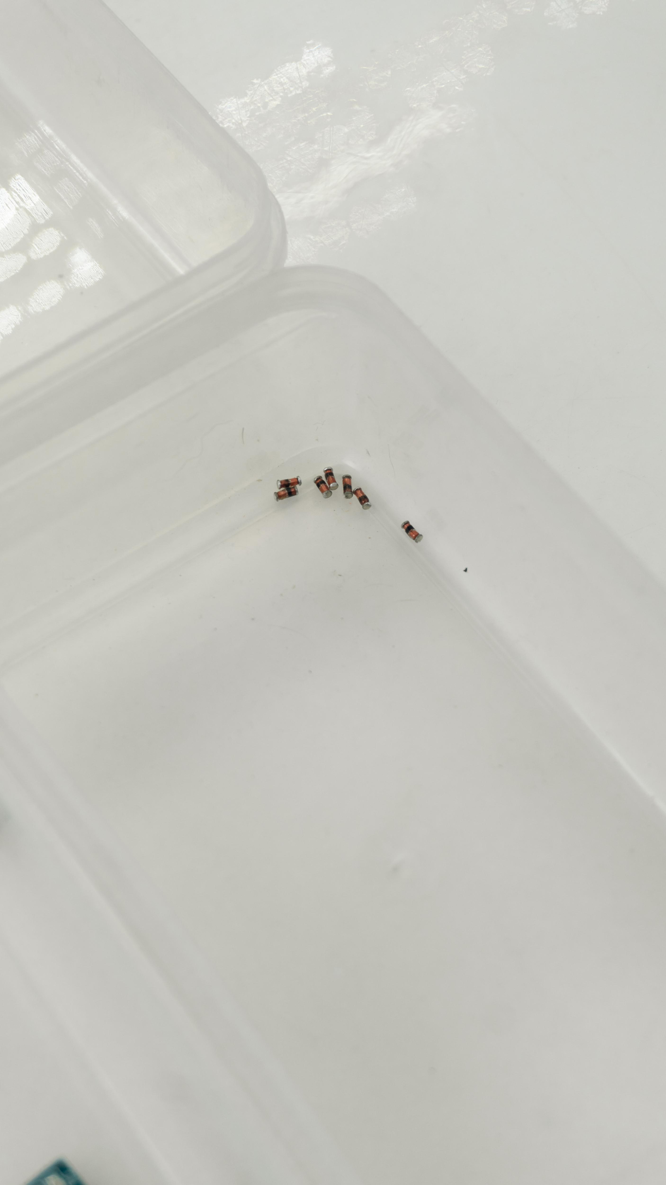
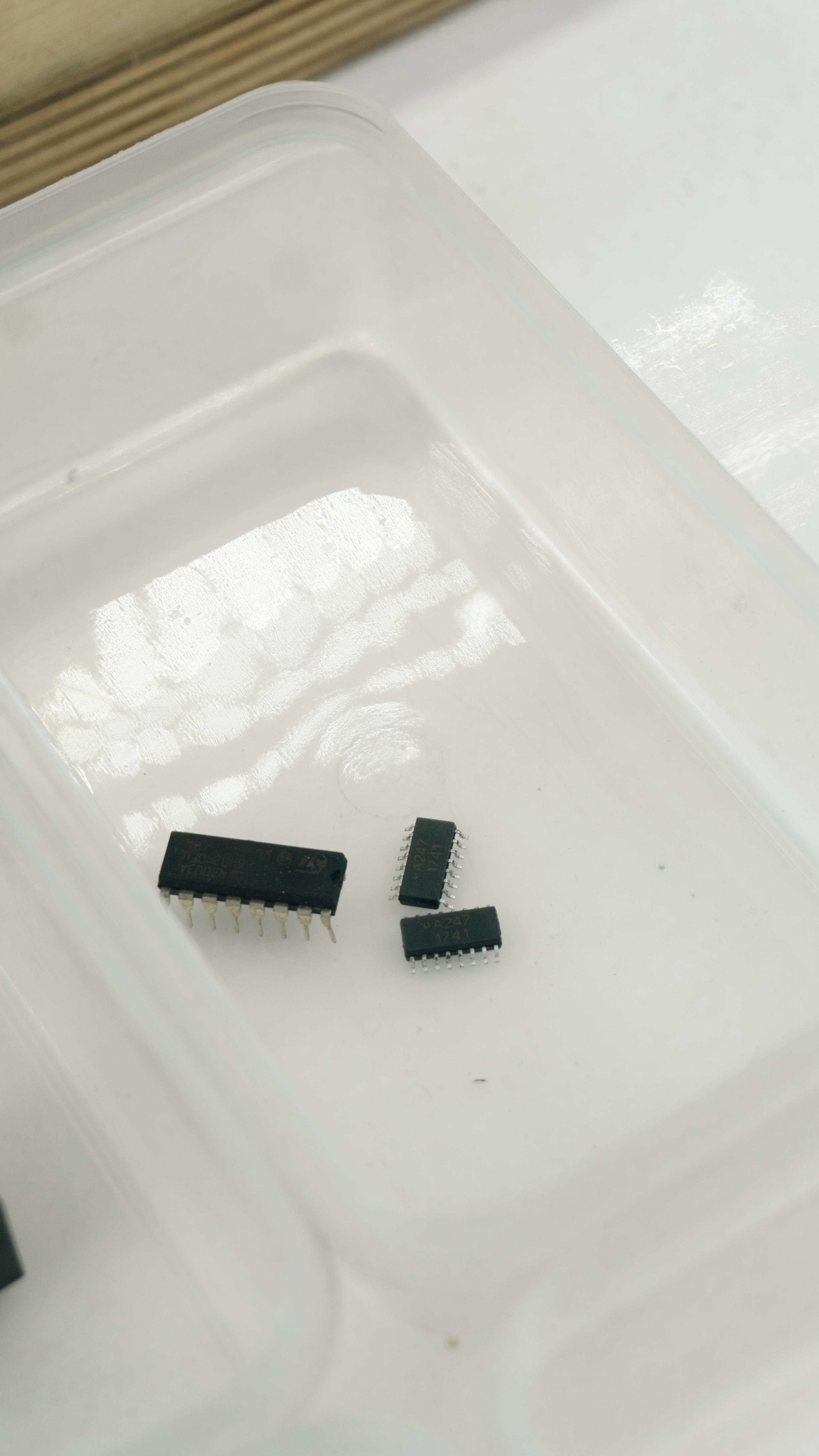
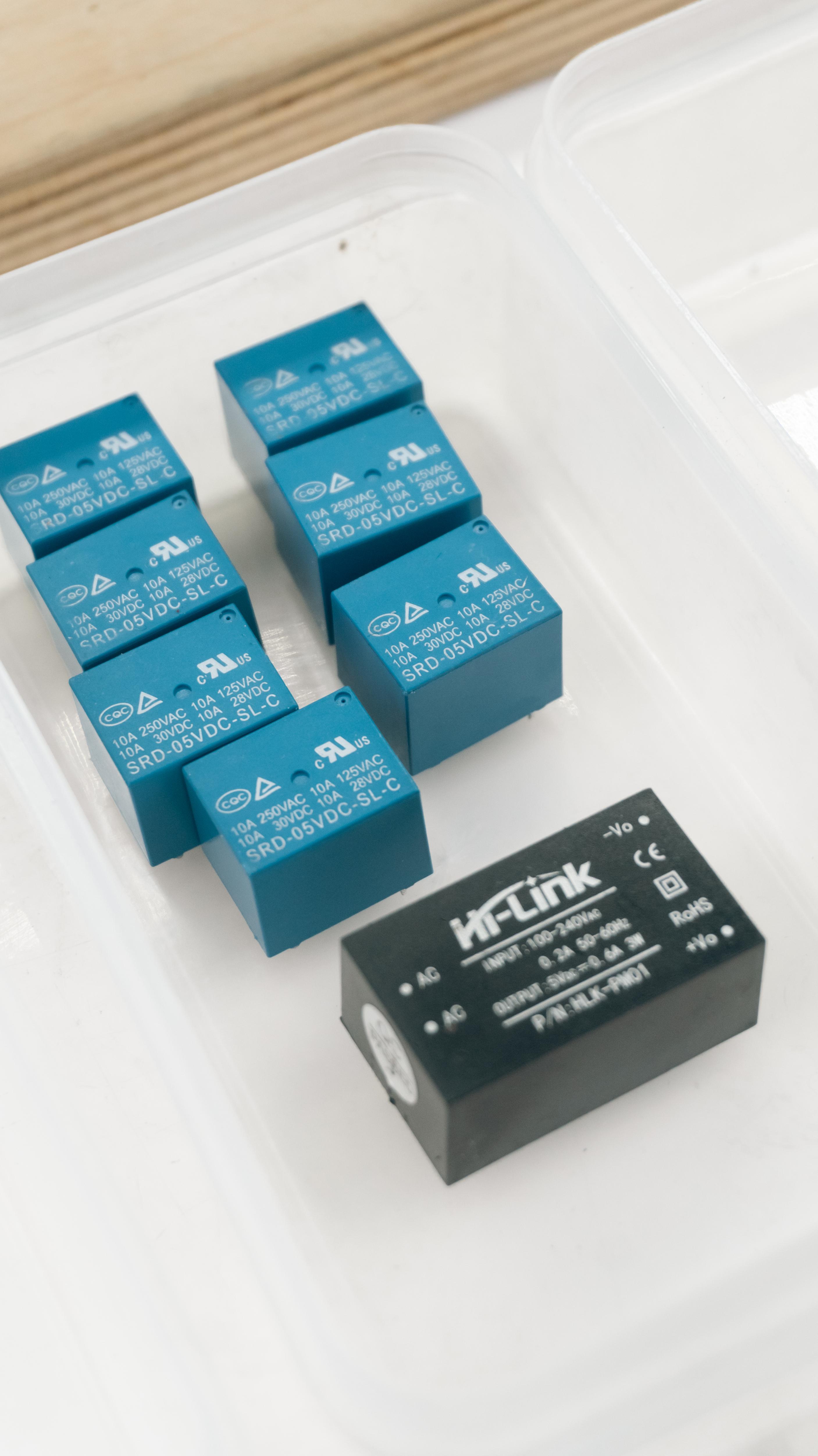
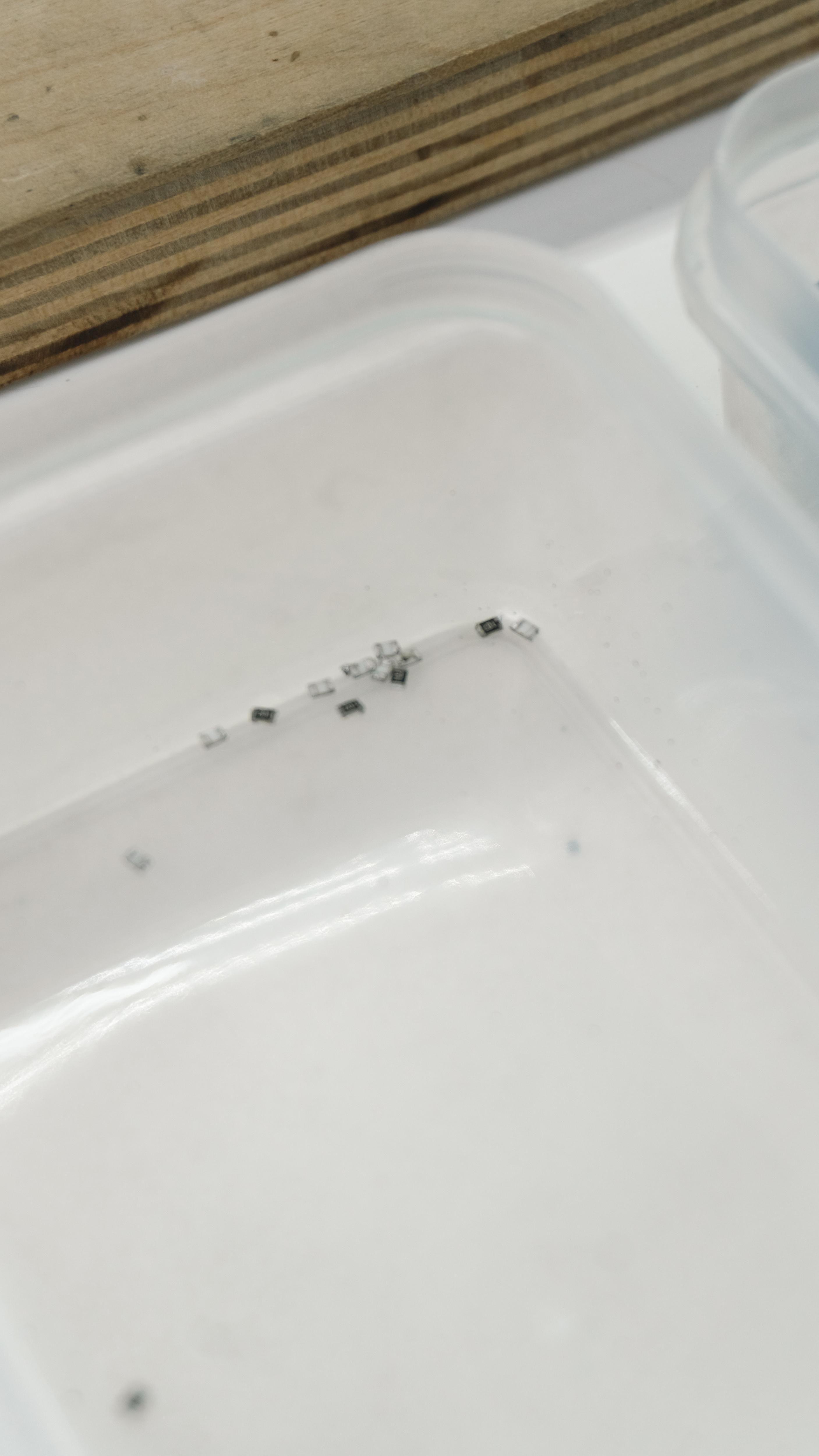
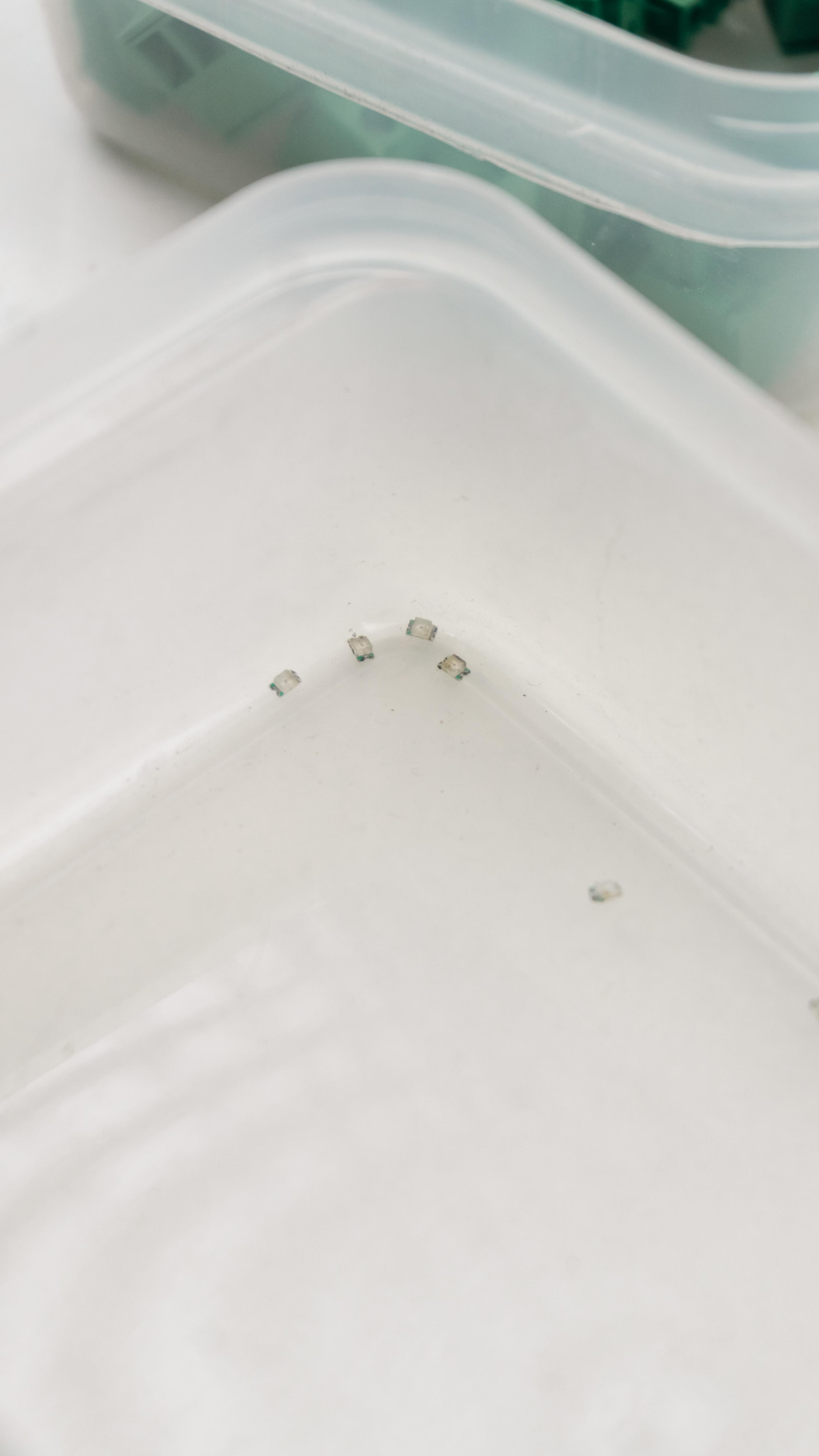
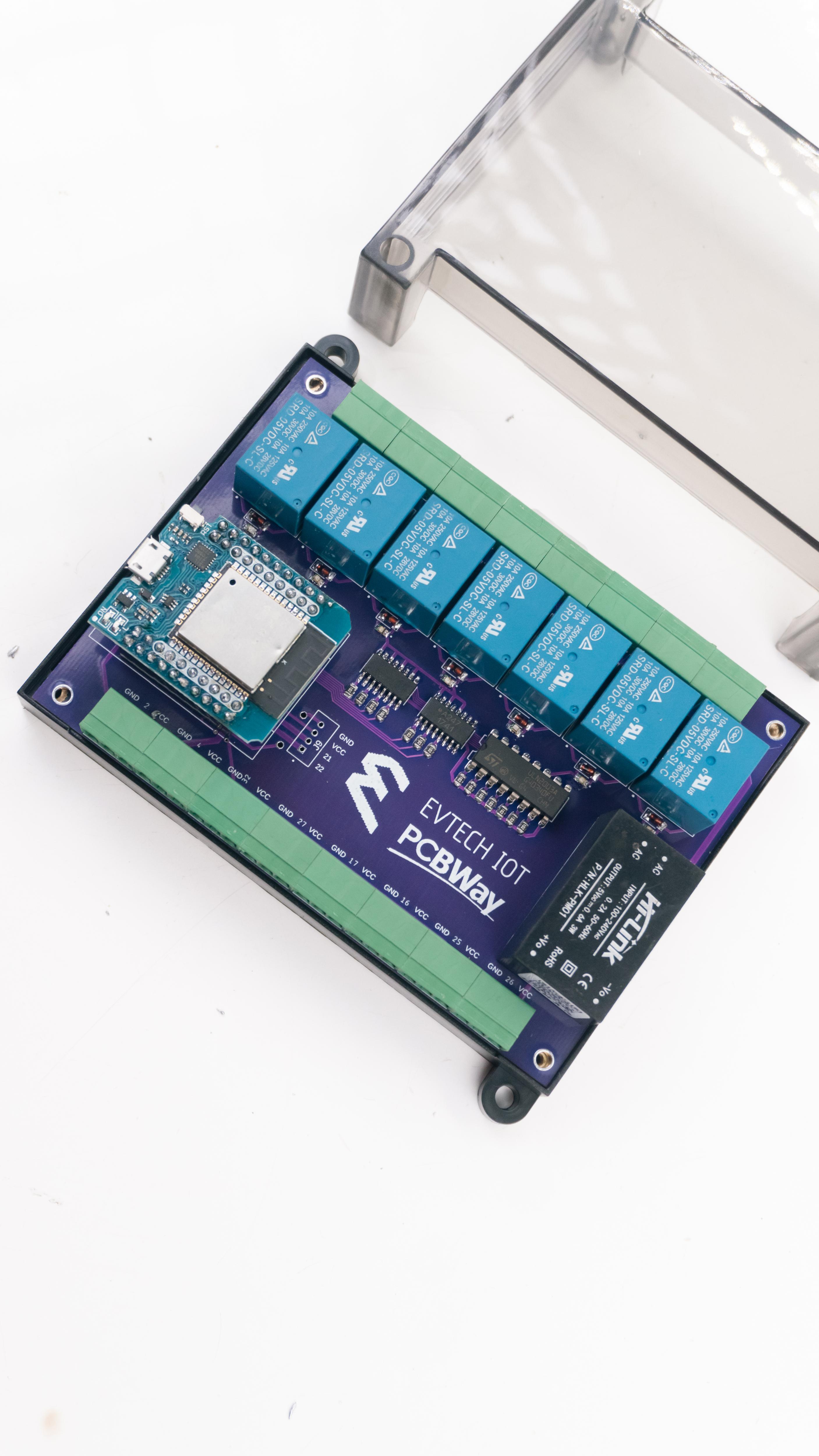
Let's start with the things that you will need. You'll need 14 pcs of 1 k ohm 0805 SMD resistor, 7 pieces of 5 volt relay, a Hi-Link 5 volt power supply, 16 pieces of terminal block, an ESP 32, 1 pc of ULN 2003A IC, and 2 pcs. Of A247 IC, 7 pieces of 0805 SMD diode, 7 pieces of 0805 SMD LED, the case of the project, the PCB stencil, and lastly, the PCB.
- 1k ohm 0805 SMD resistor (14x)
- 5 volt relay (7x)
- Hi-Link 5 volt power supply
- Terminal block (16x)
- ESP 32
- ULN 2003A IC
- A247 IC (2x)
- 0805 SMD diode (7x)
- 0805 SMD LED (7x)
- Case of the project
- PCB stencil
- PCB
Soldering Time!
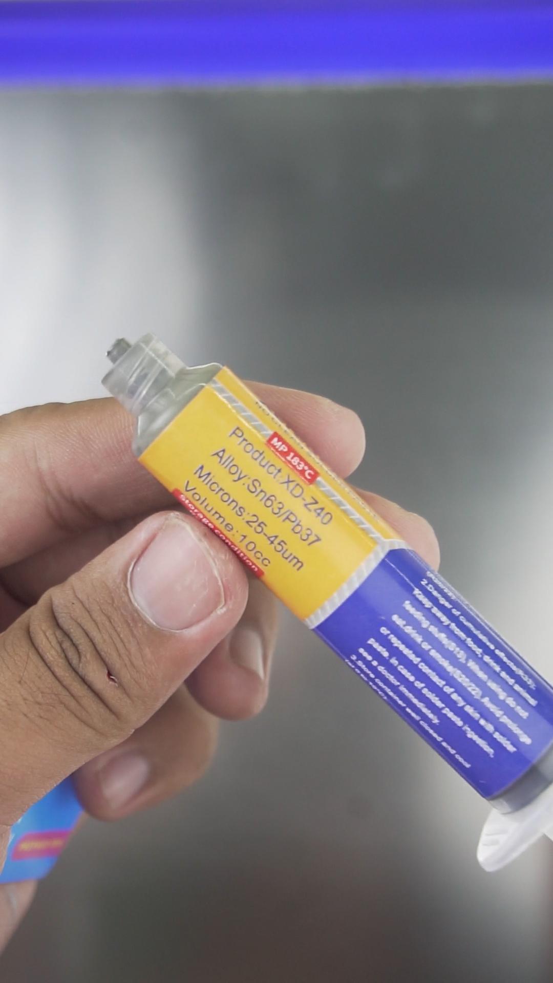
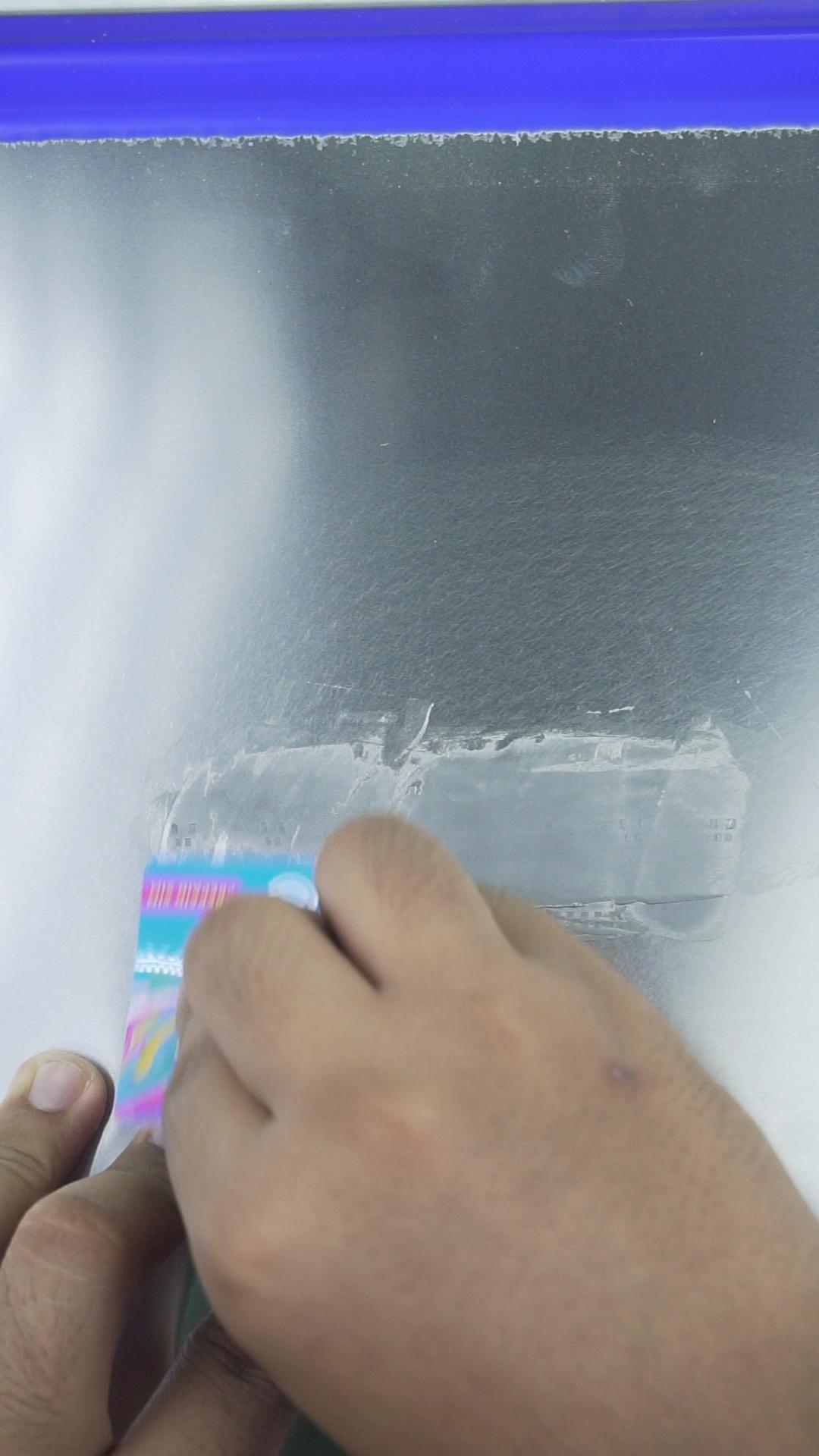
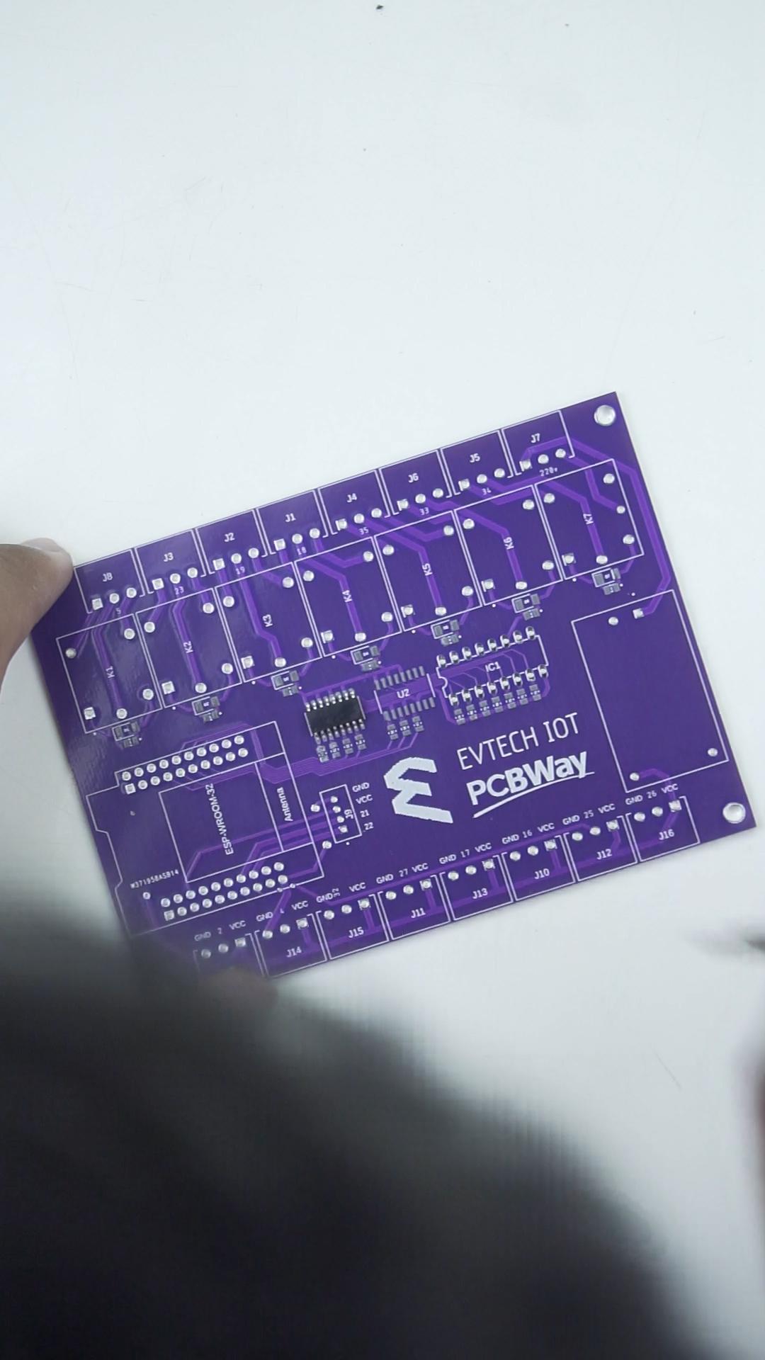
We'll start by putting the stencil on top of the PCB; after that, we are going to apply a decent amount of solder paste and spread it to the place with a hole in the stencil. After doing that, it's time to remove the stencil on top of the PCB. As you can see, using the PCB stencil helps us place solder paste on a PCB board for surface mount component placement more accurately, so make sure when you order your PCB from PCBWay, make sure to get a stencil, especially when you are working with SMD components.
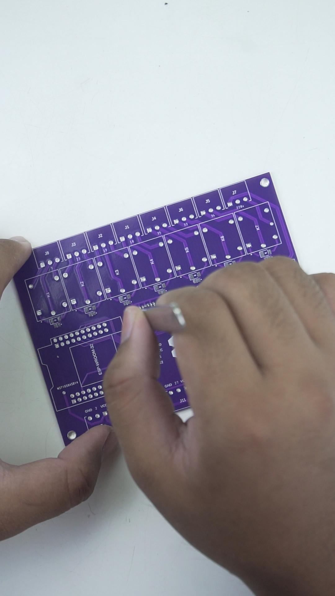
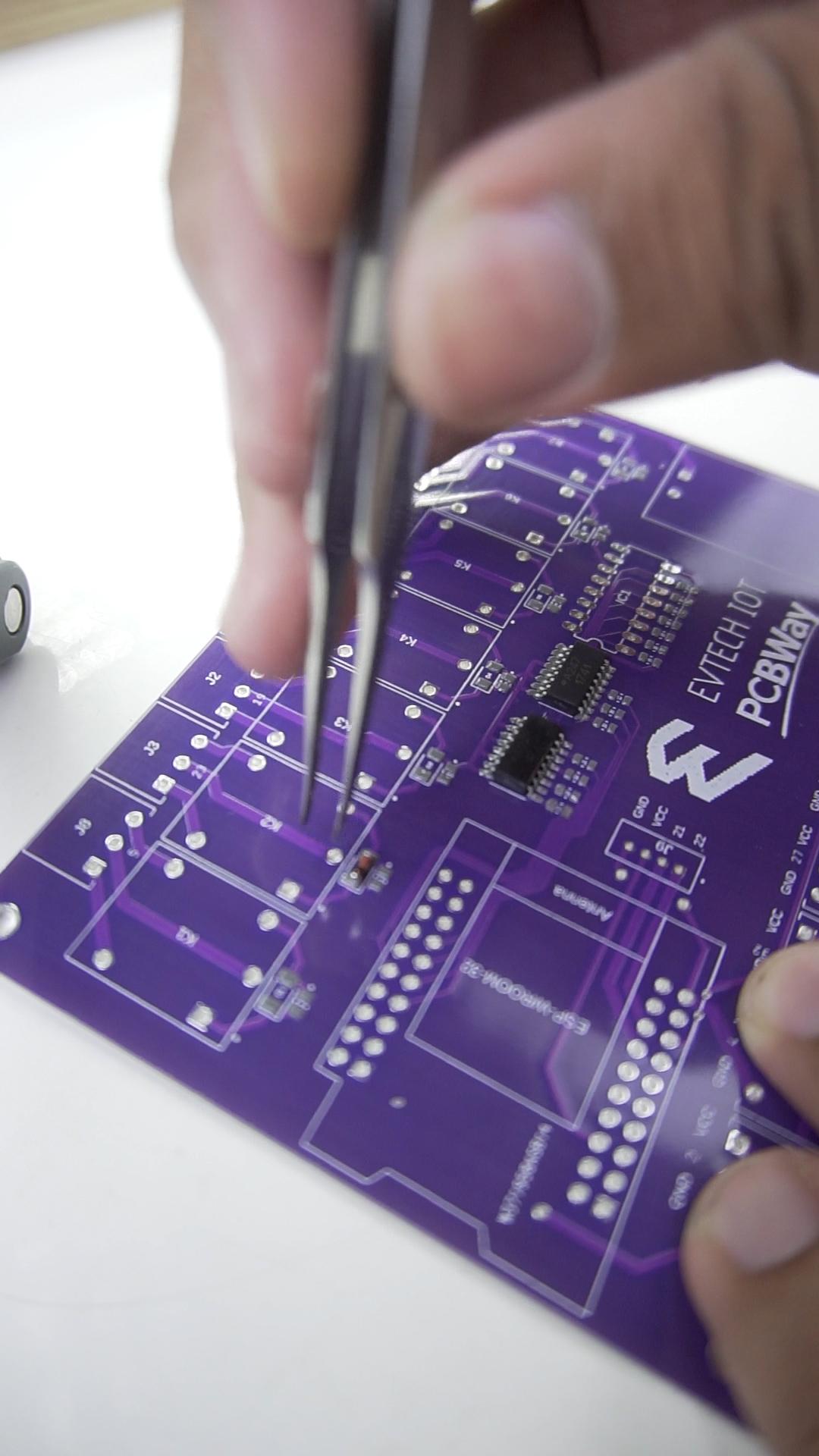
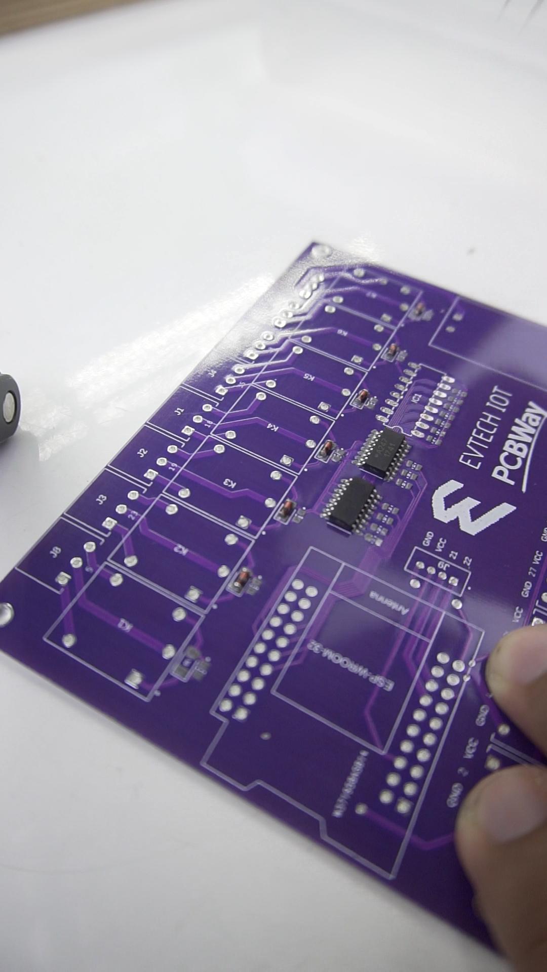
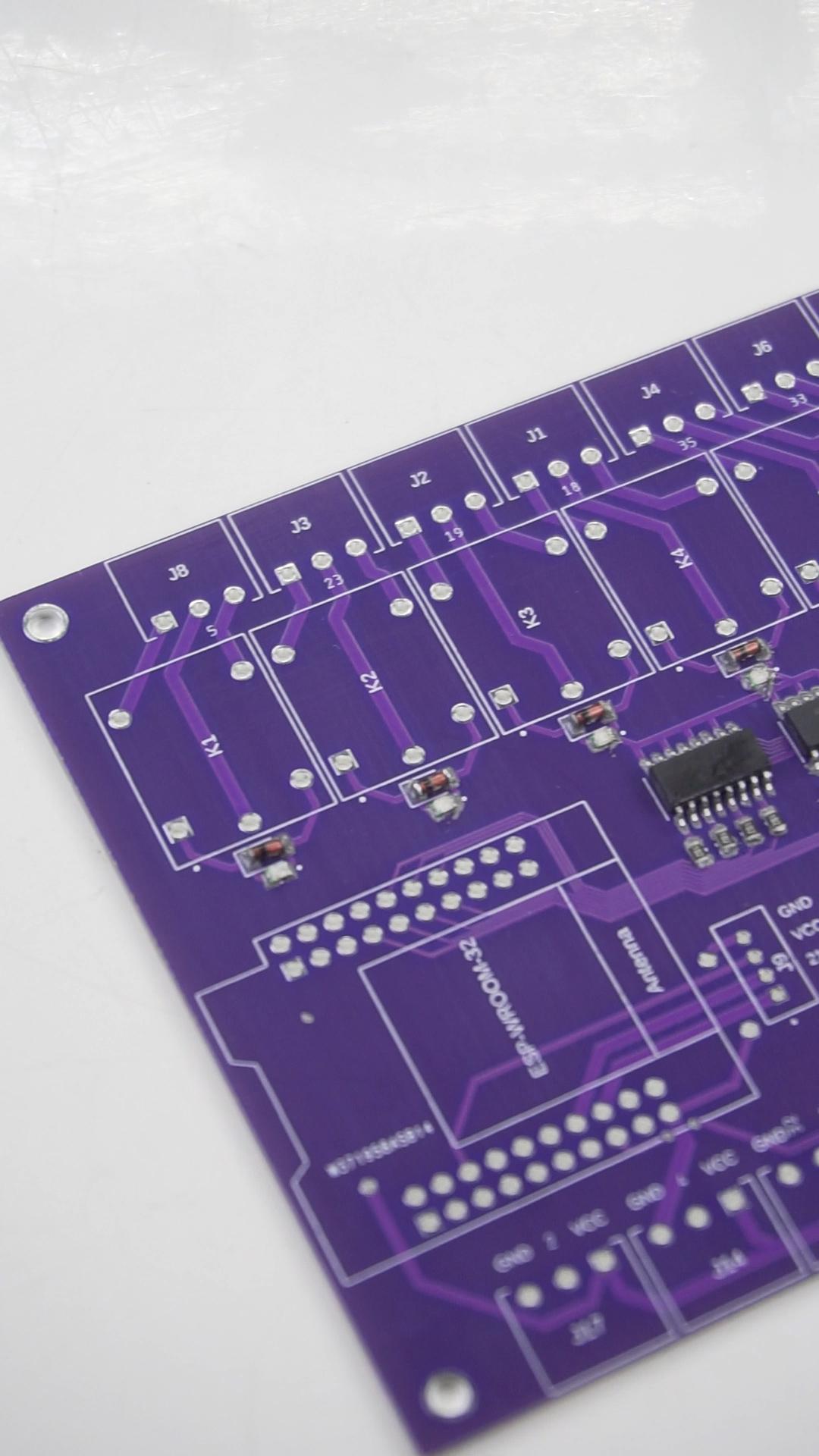
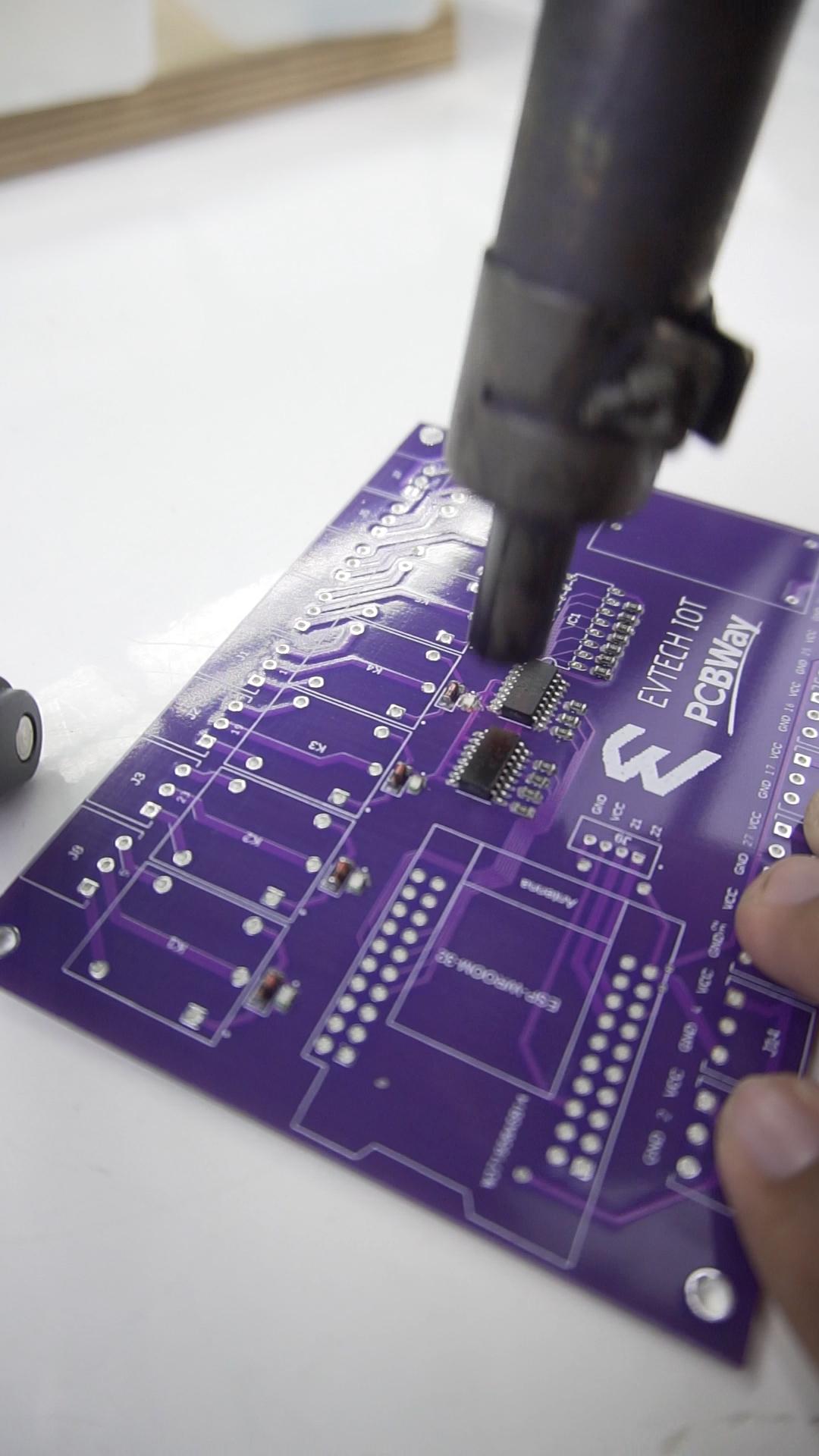
Next to that, it's time to put all the SMD components in place, starting with the A247 IC, followed by the SMD diode, LED, and resistor. Look at that! It really looks awesome! Now, using a hot air rework station, the solder paste melts and effectively sucks the component into the right position.
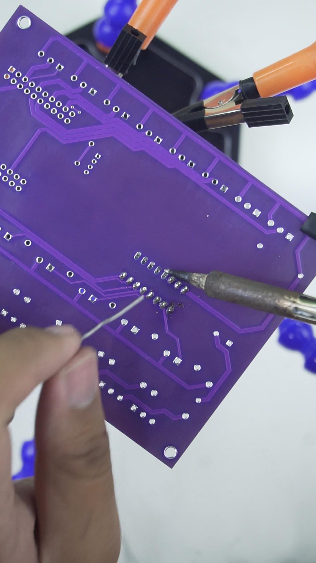
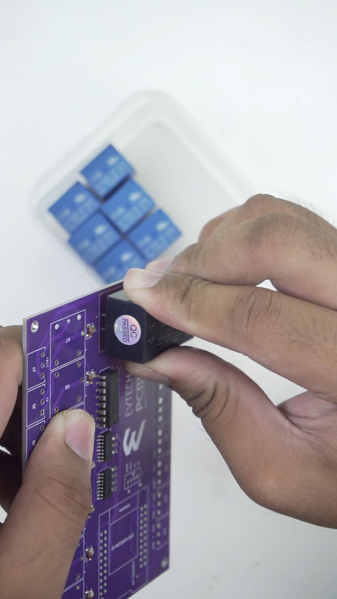
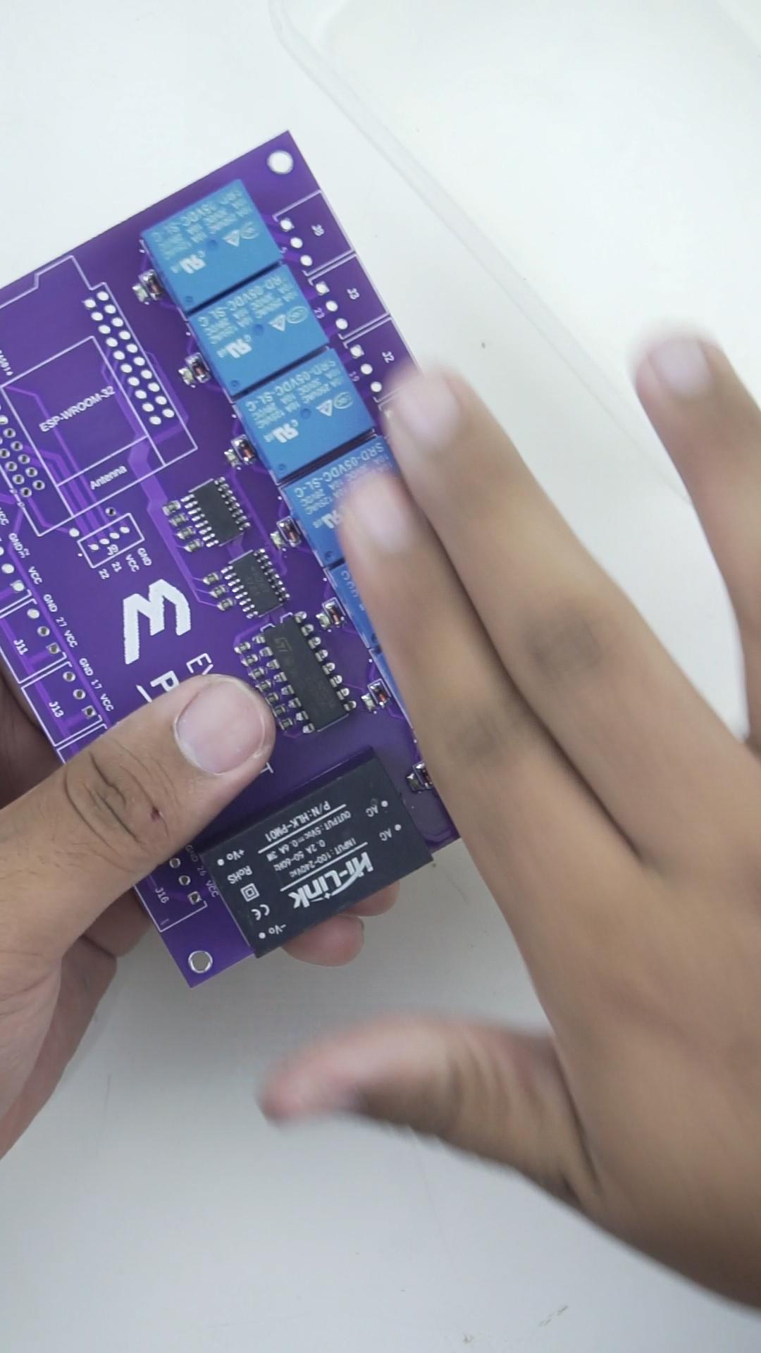
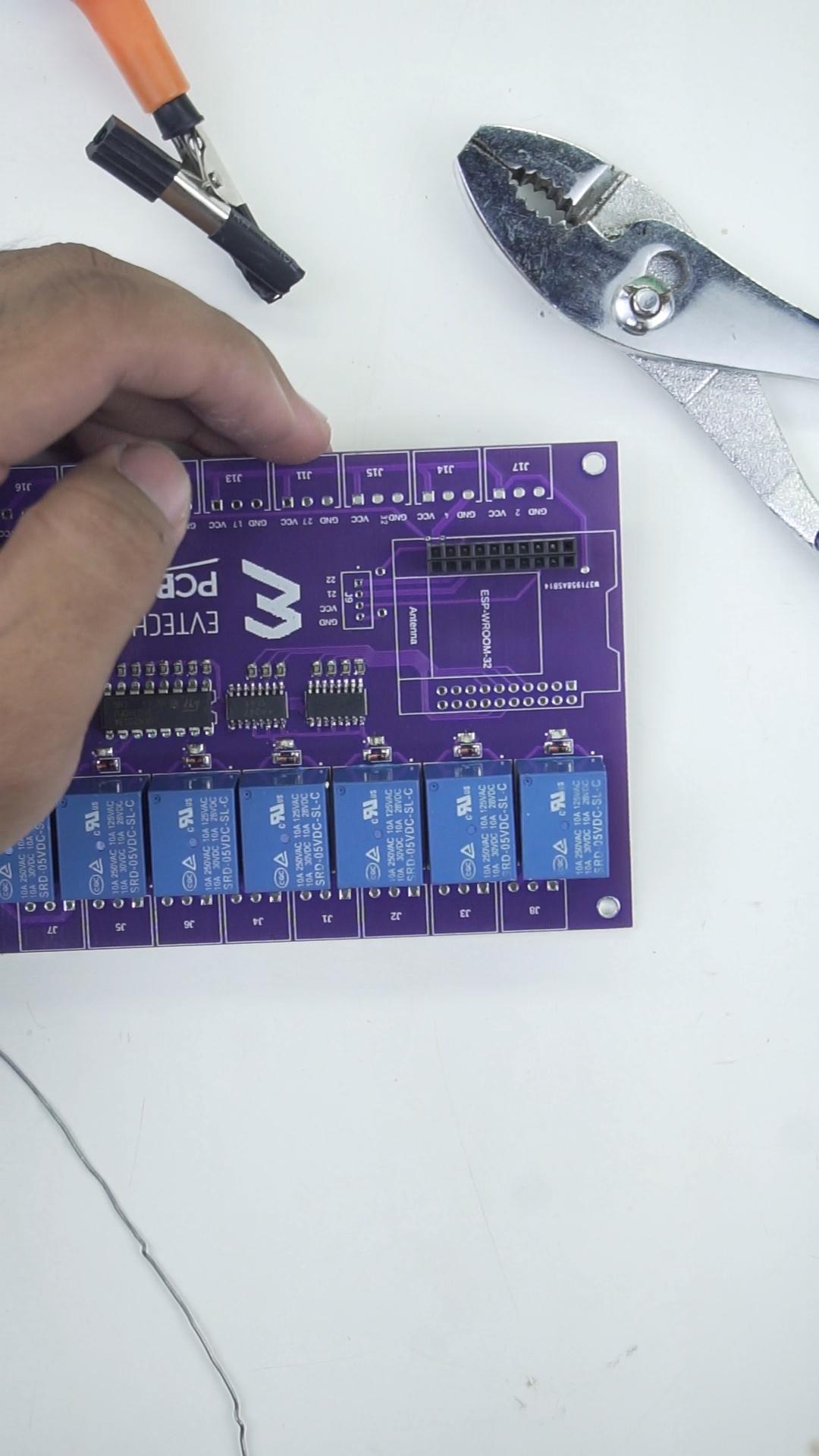
After that, it's time to solder all the THT components, starting with the ULN 2003A IC, followed by the Hi-Link 5 volt power supply, the 5 volt relay, the female header pins for the ESP32, the male pin for the ESP32, and lastly the terminal blocks.
And we're finally done with the hardware part! Let's go to the Blynk website!
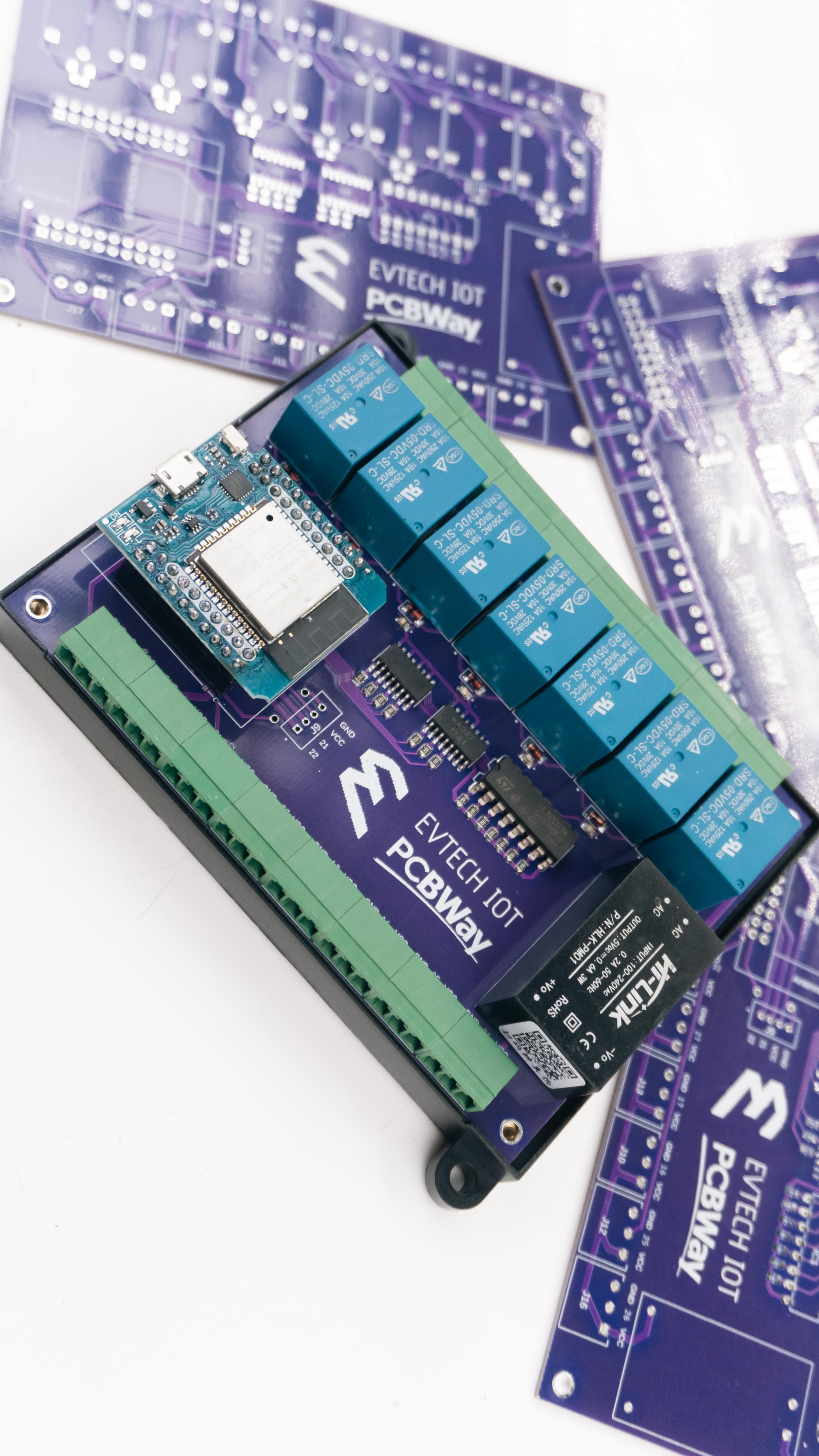
PCBWay

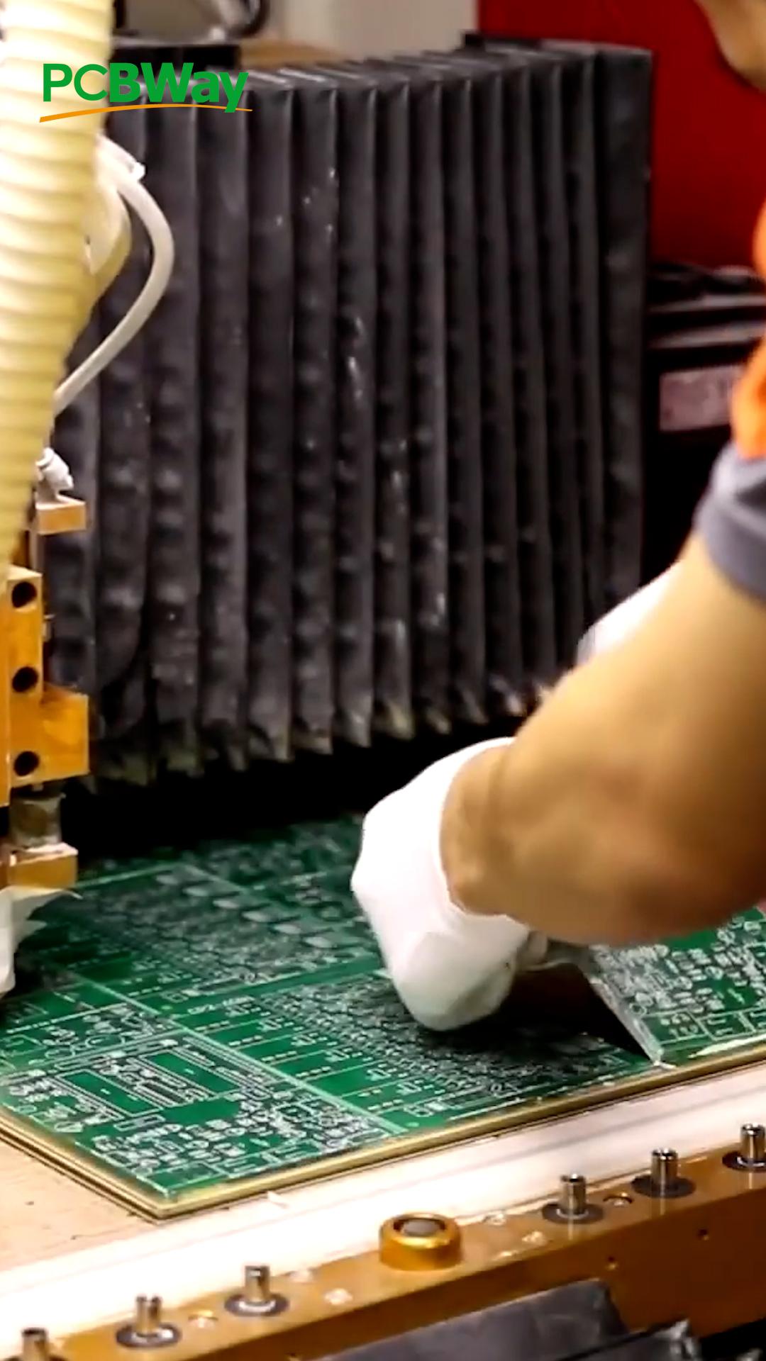
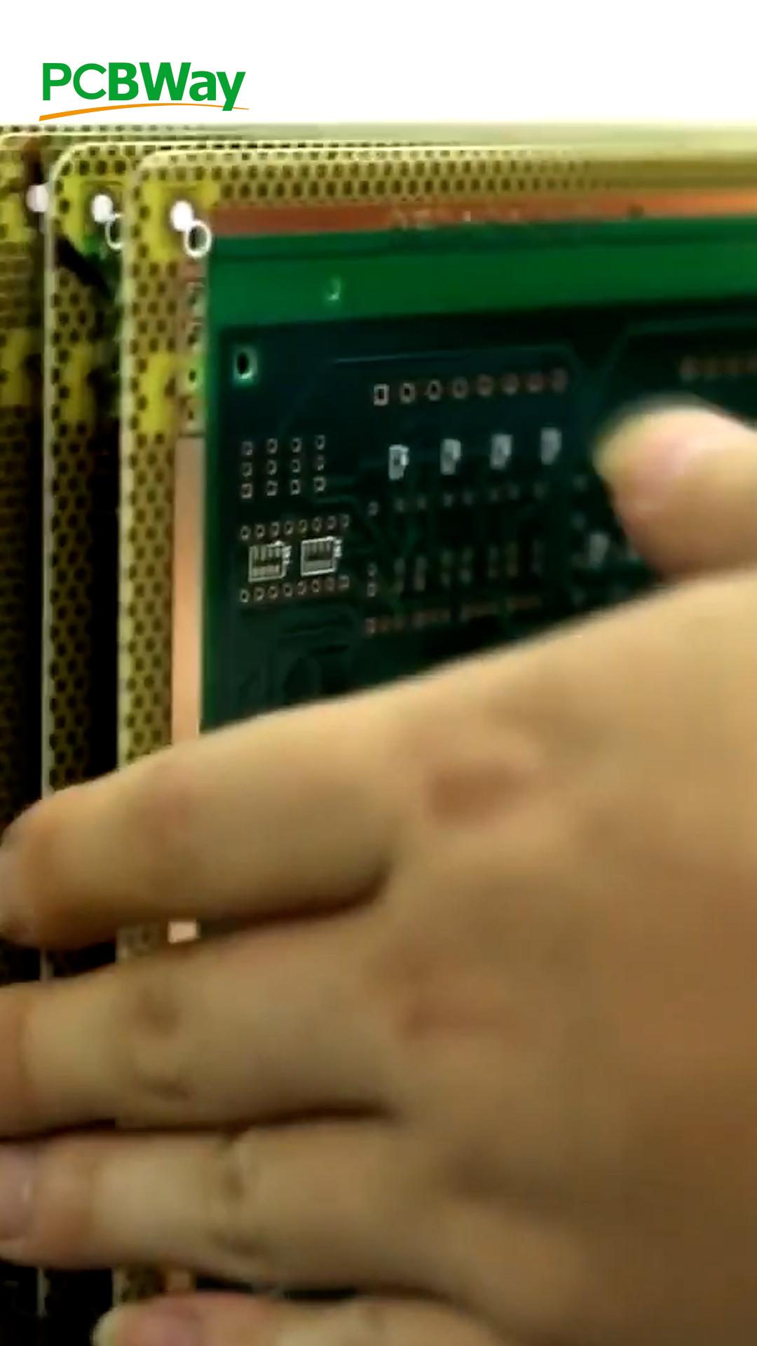
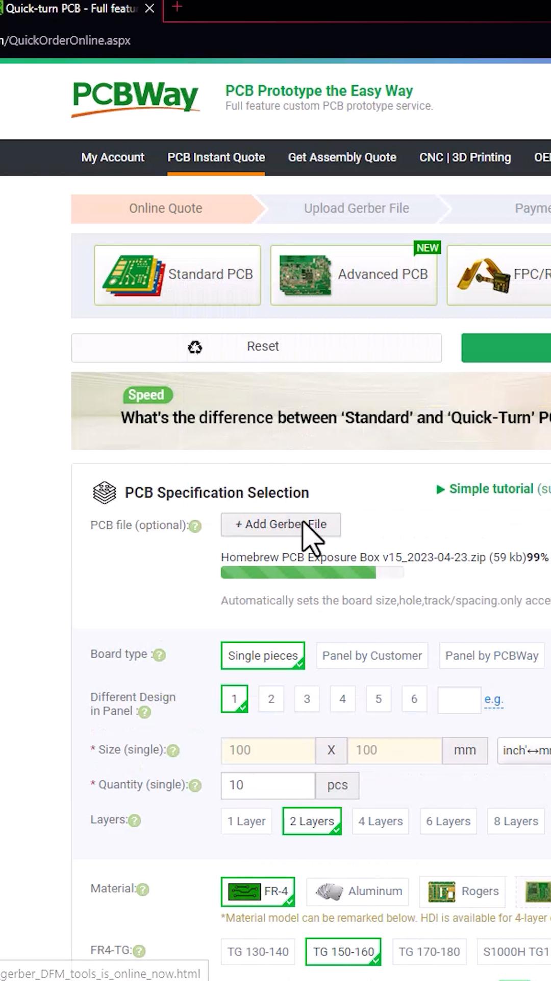
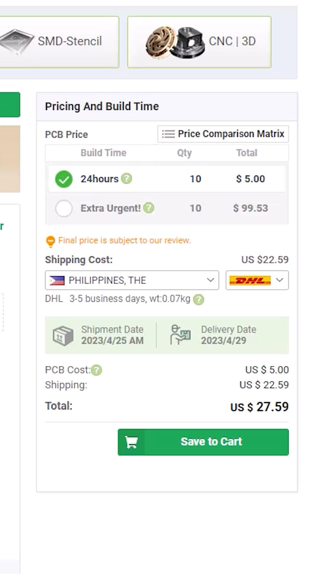
If you are interested in the Gerber. You can find it in the GitHub file package link. You can buy 10 pieces of the board for $5 (be sure to input 10pcs. since 5pcs is set by default). I do appreciate it when you buy from my PCBway link, I use the commission to fund my other projects and tutorials, your support would be much appreciated.
GitHub Link: (https://bit.ly/3NRA8nP)
PCBWay Link: (https://bit.ly/PCBWayEvtech)
Setting Up the Blynk

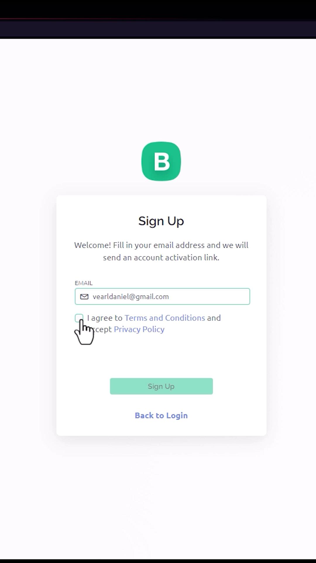
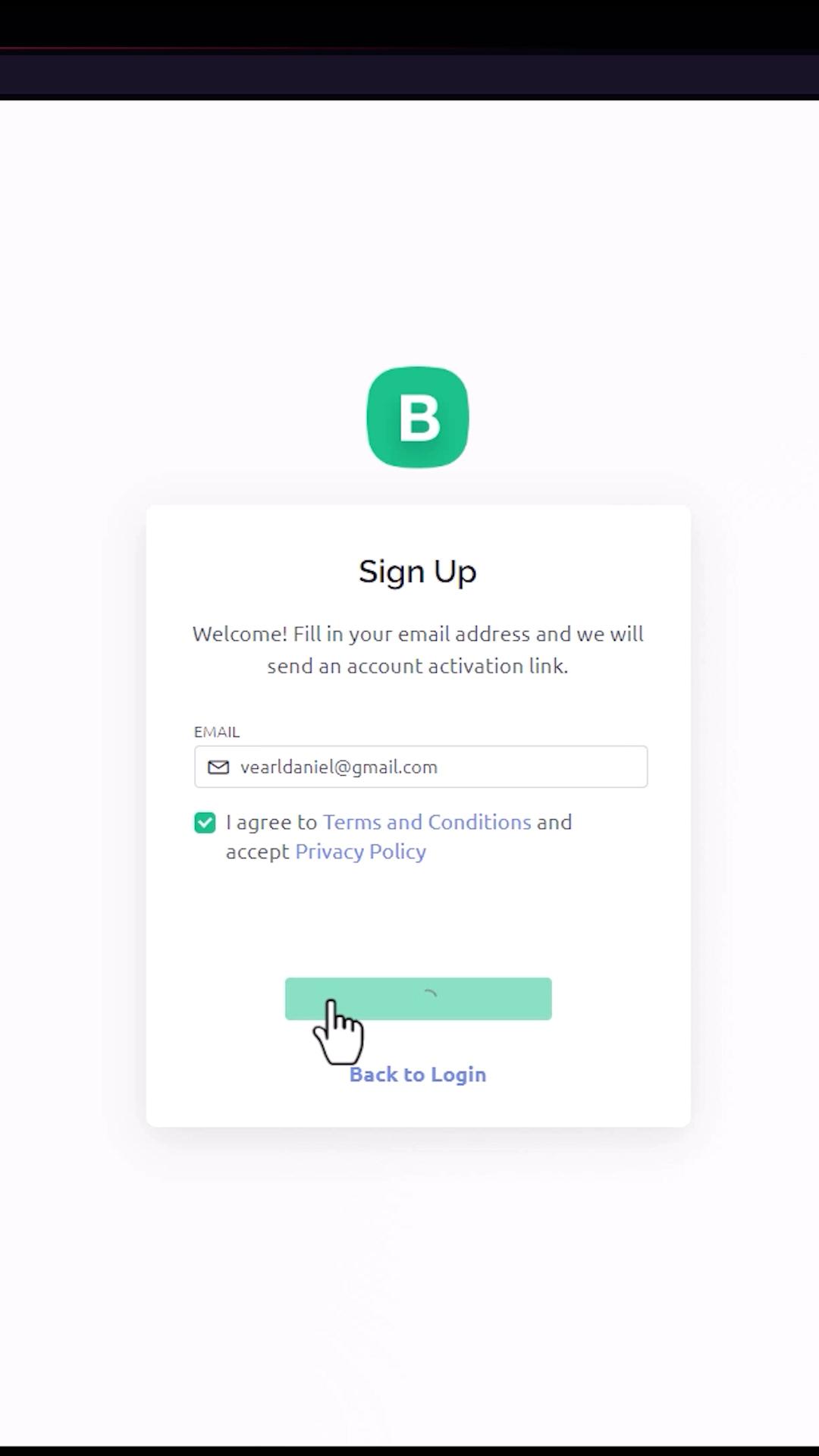
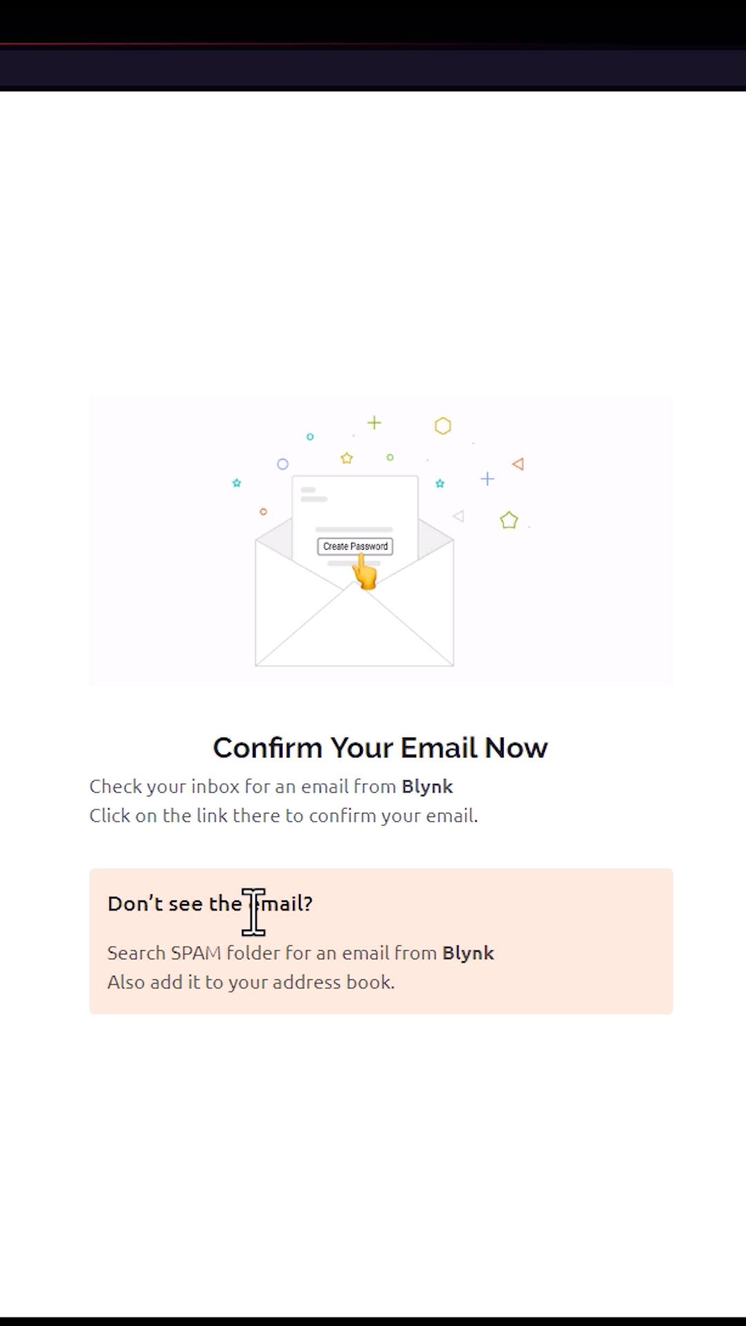
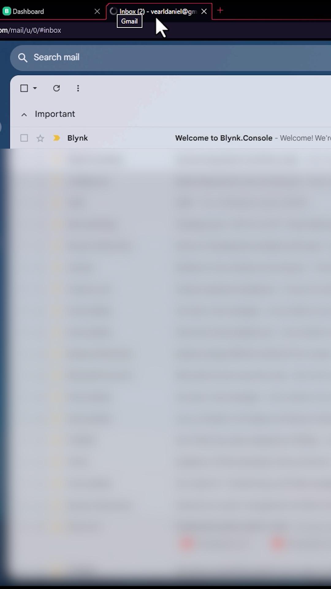
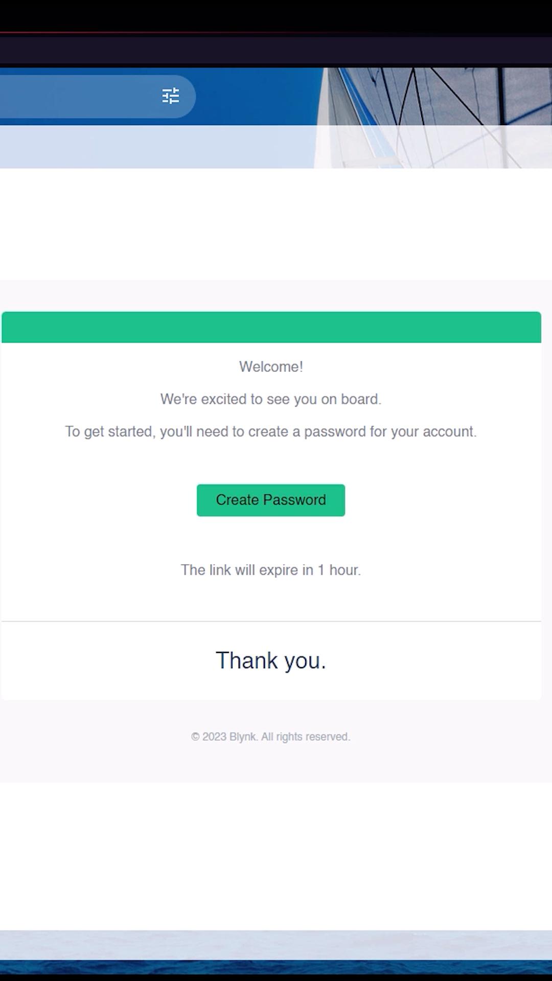
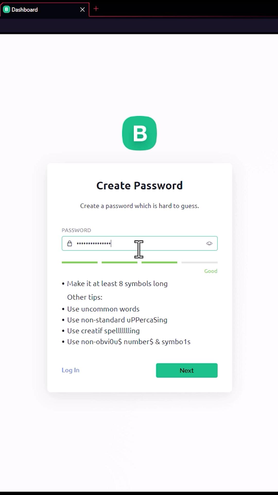
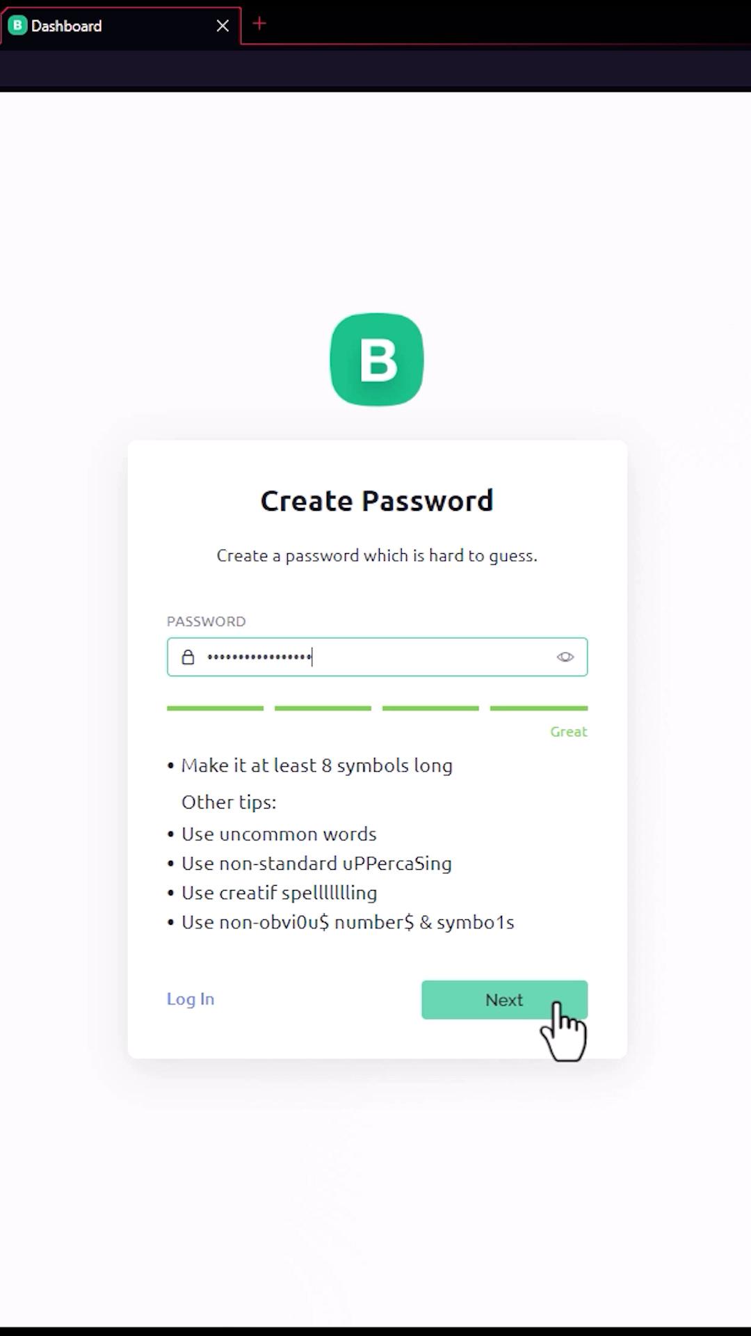
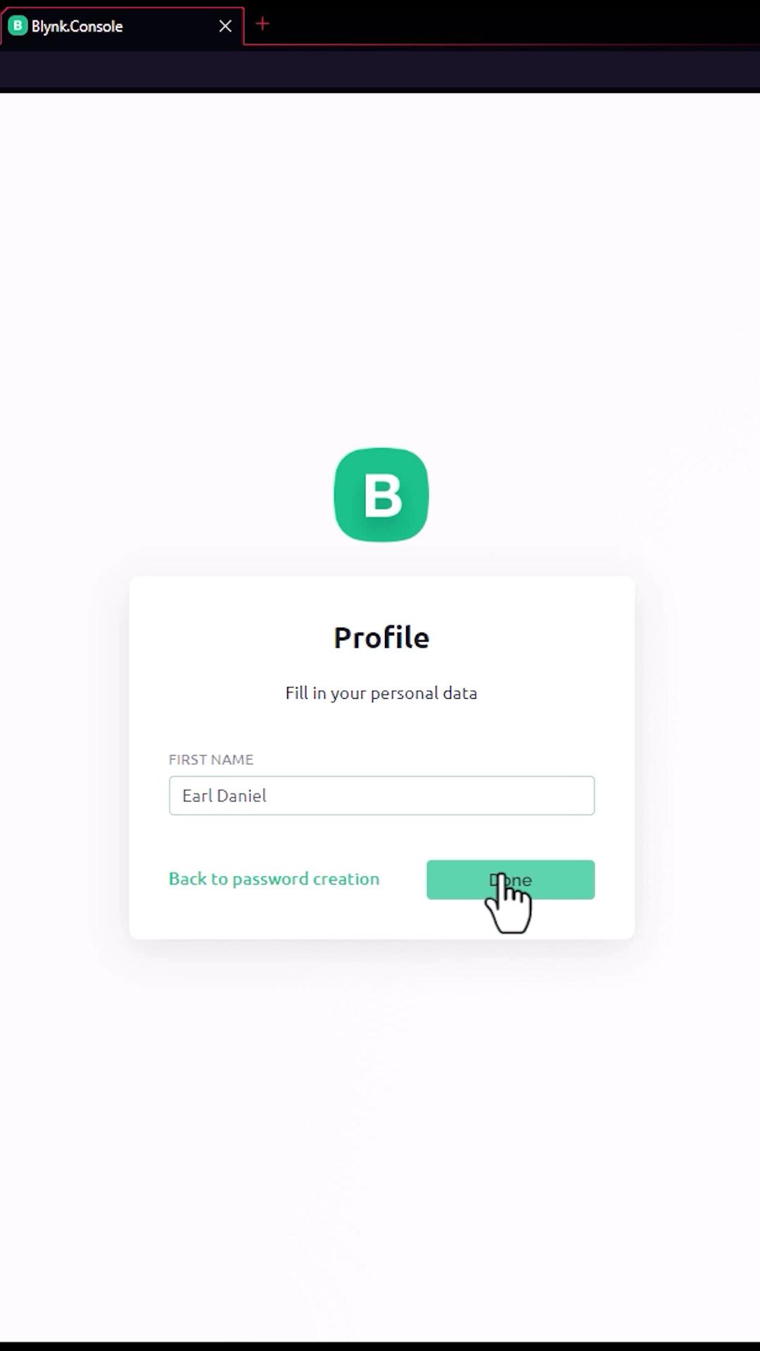


For this project, we need a Blynk account. Go to blynk.io, click "Start Free" to sign up, enter your email, check this box, and click Sign Up." After that, you need to confirm your email by going to your email inbox, clicking the blynk and clicking create password. After that, it will direct you to a website where you can enter your password. Click next, then enter your first name, and hit done.
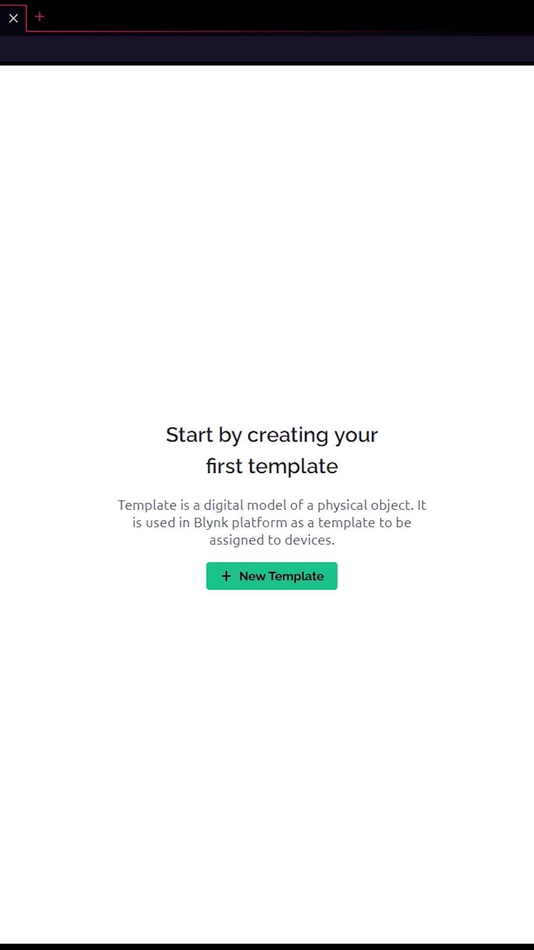
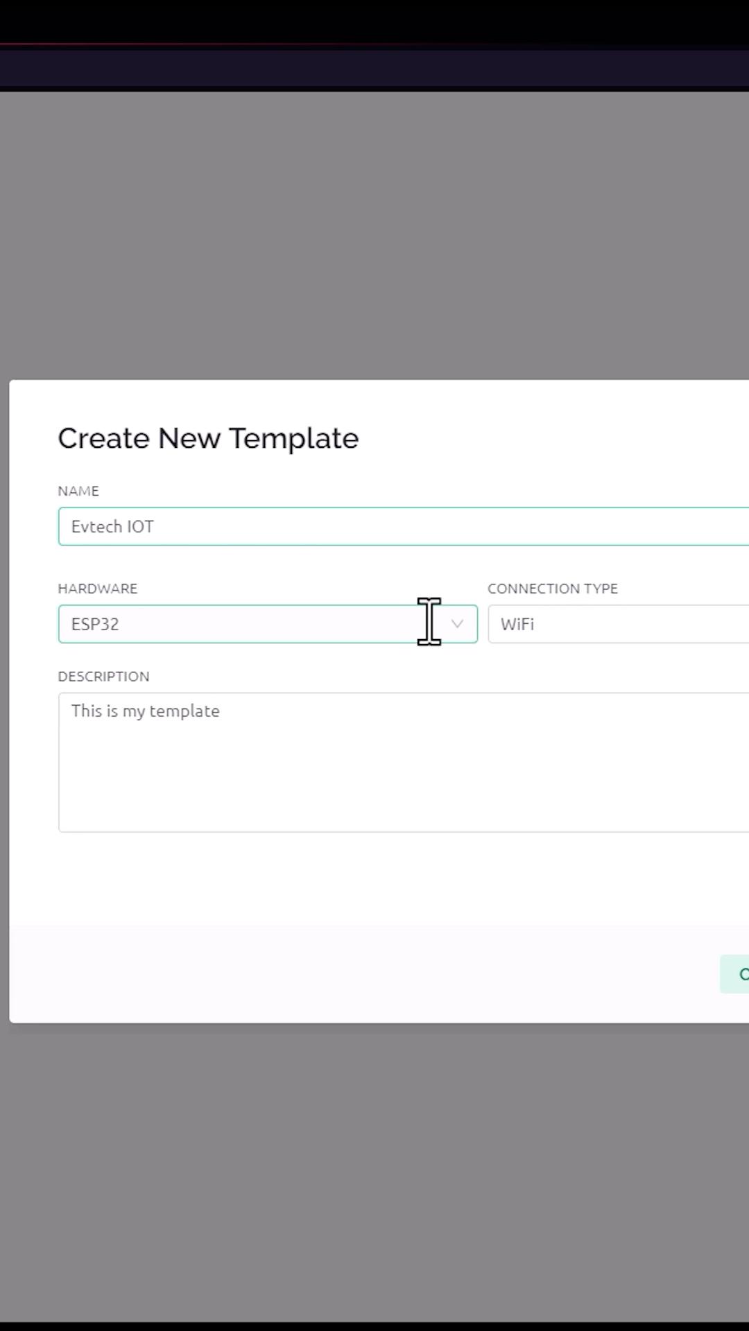
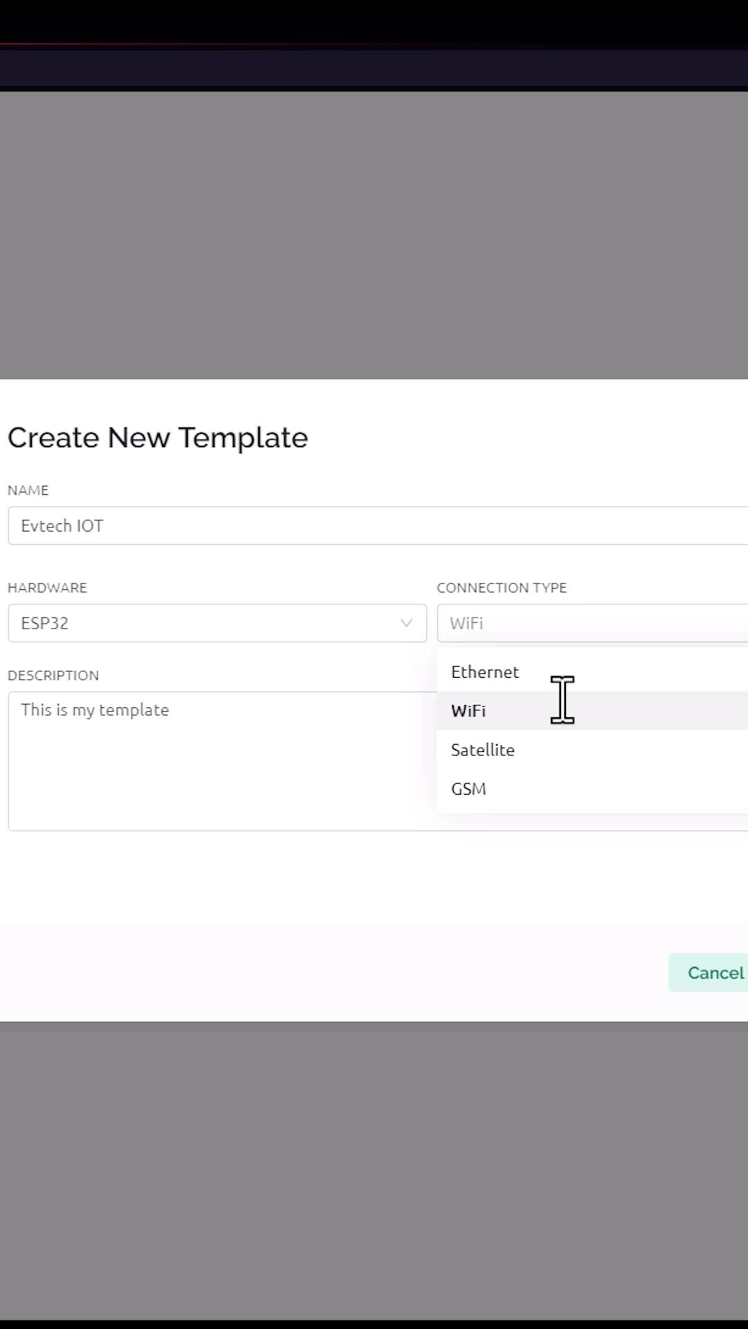
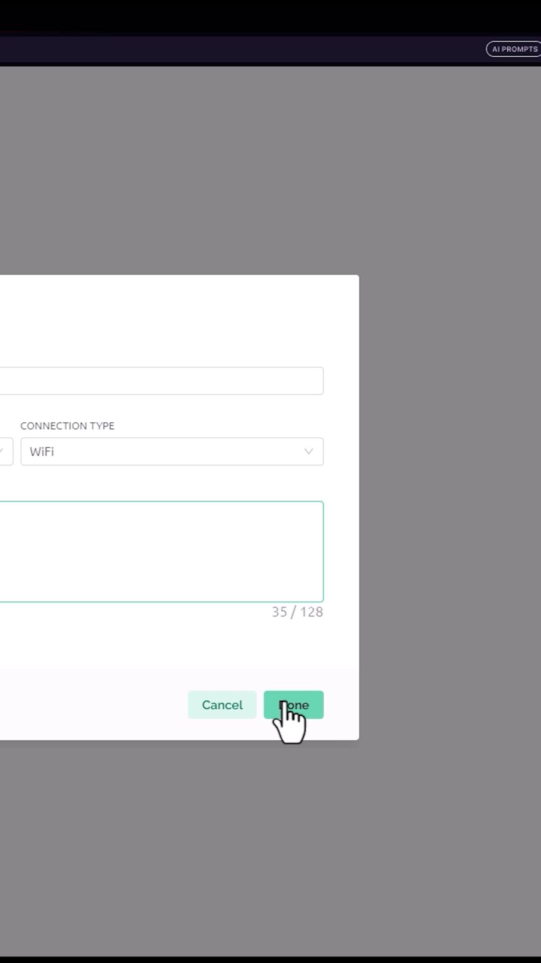
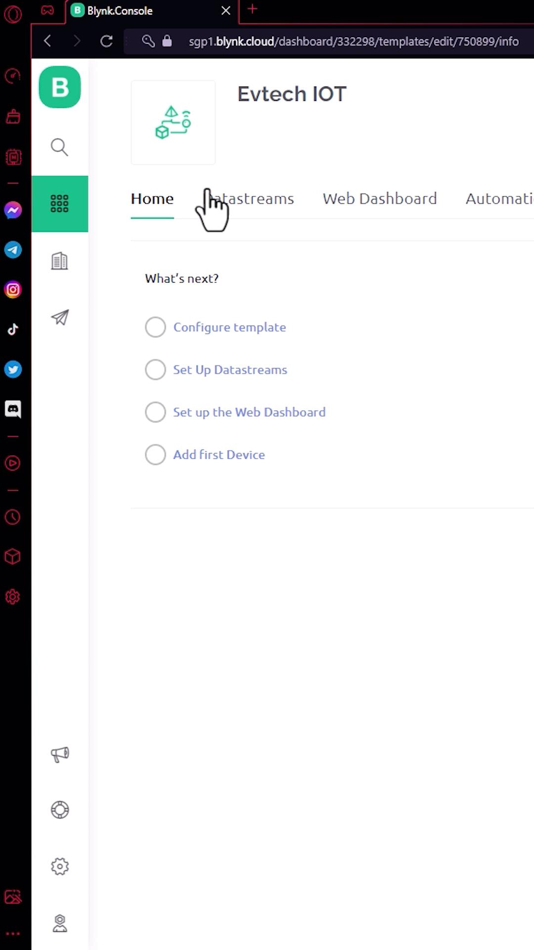
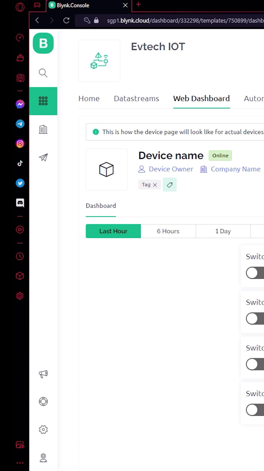
Here's the dashboard of the Blynk. The first thing that we need to do here is create a new template. In here, enter the name of your template, select the hardware as esp32, and the connection type as Wi-Fi. After that, click done.
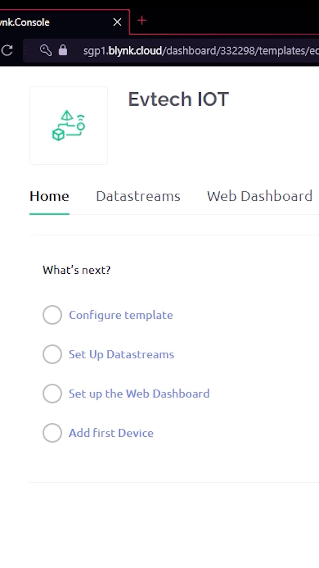
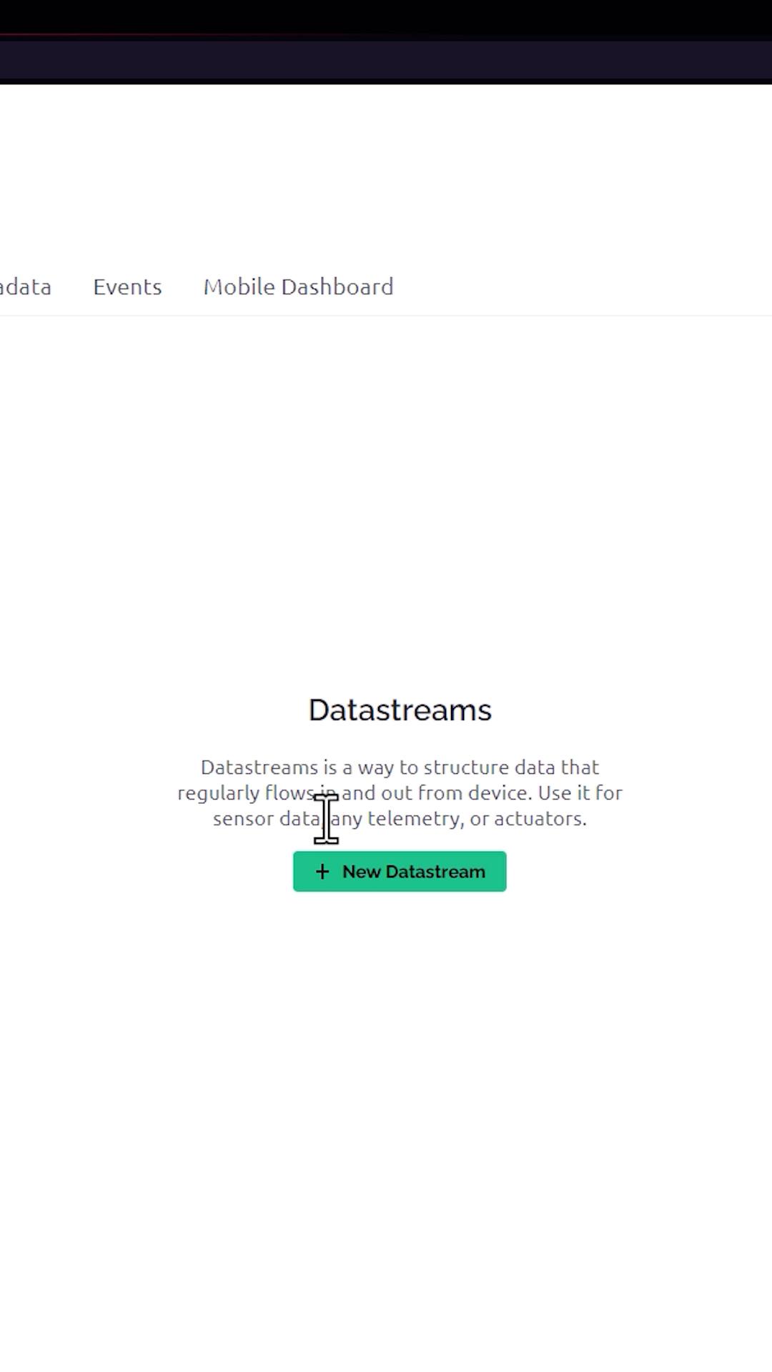
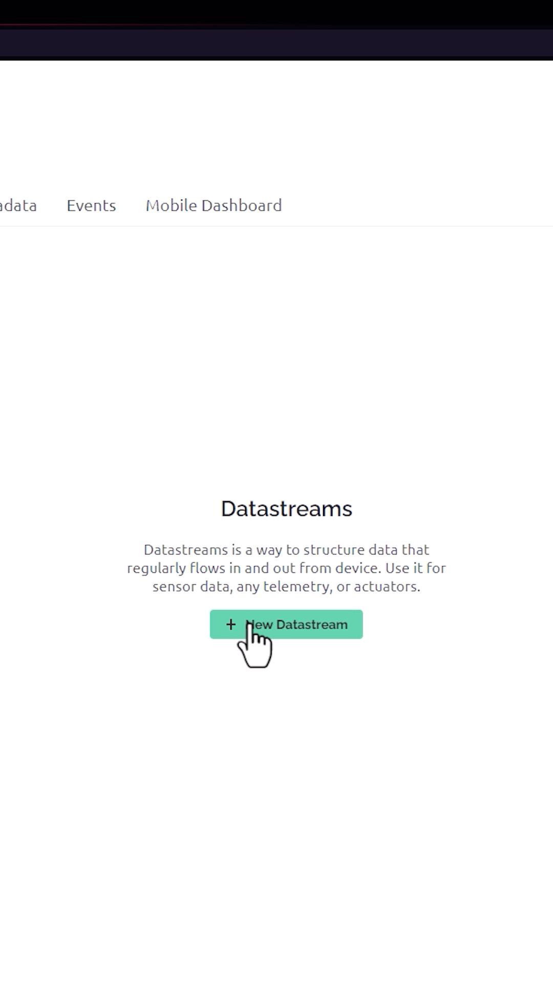
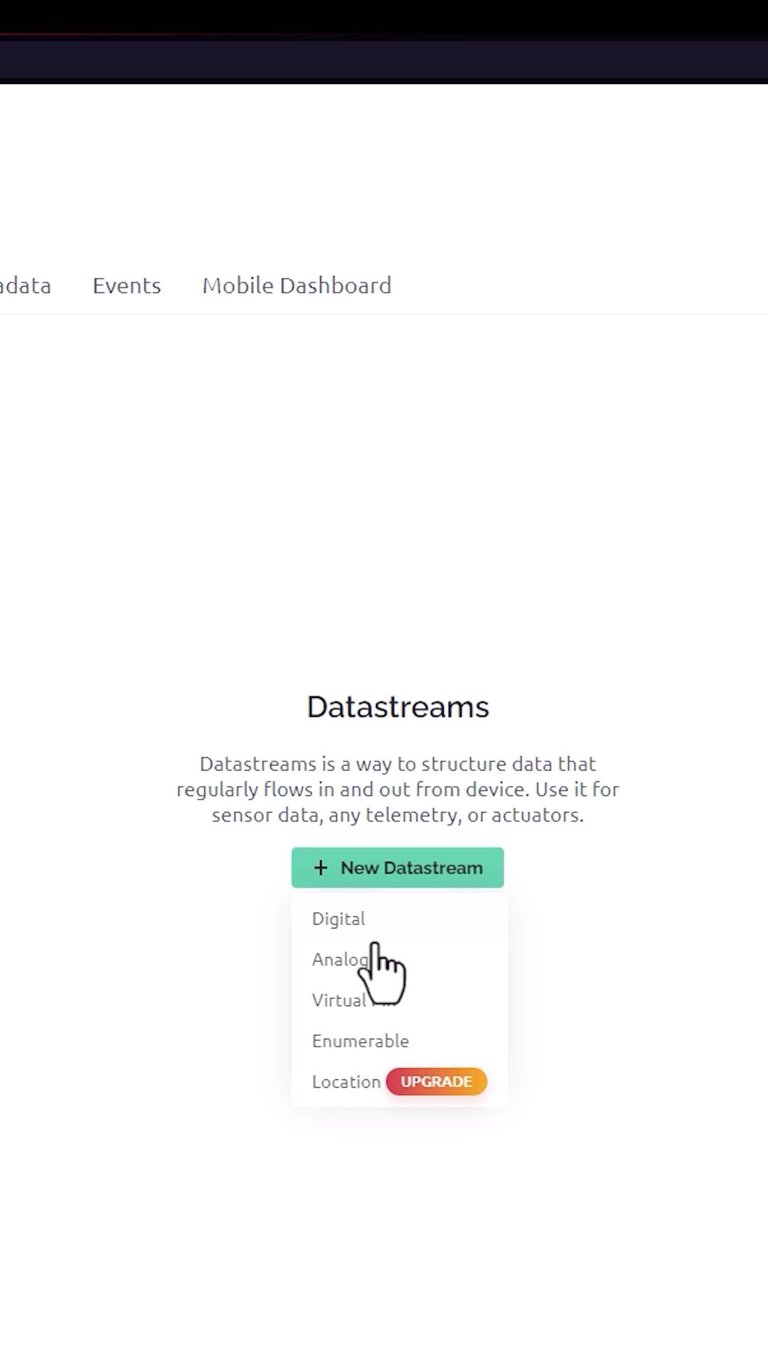
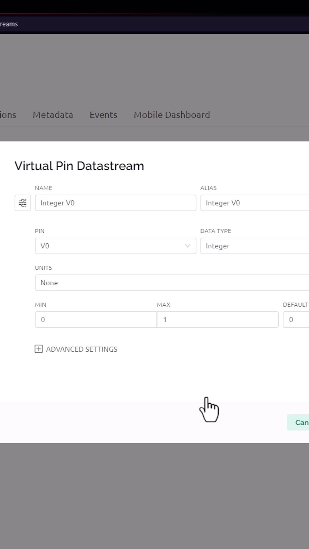
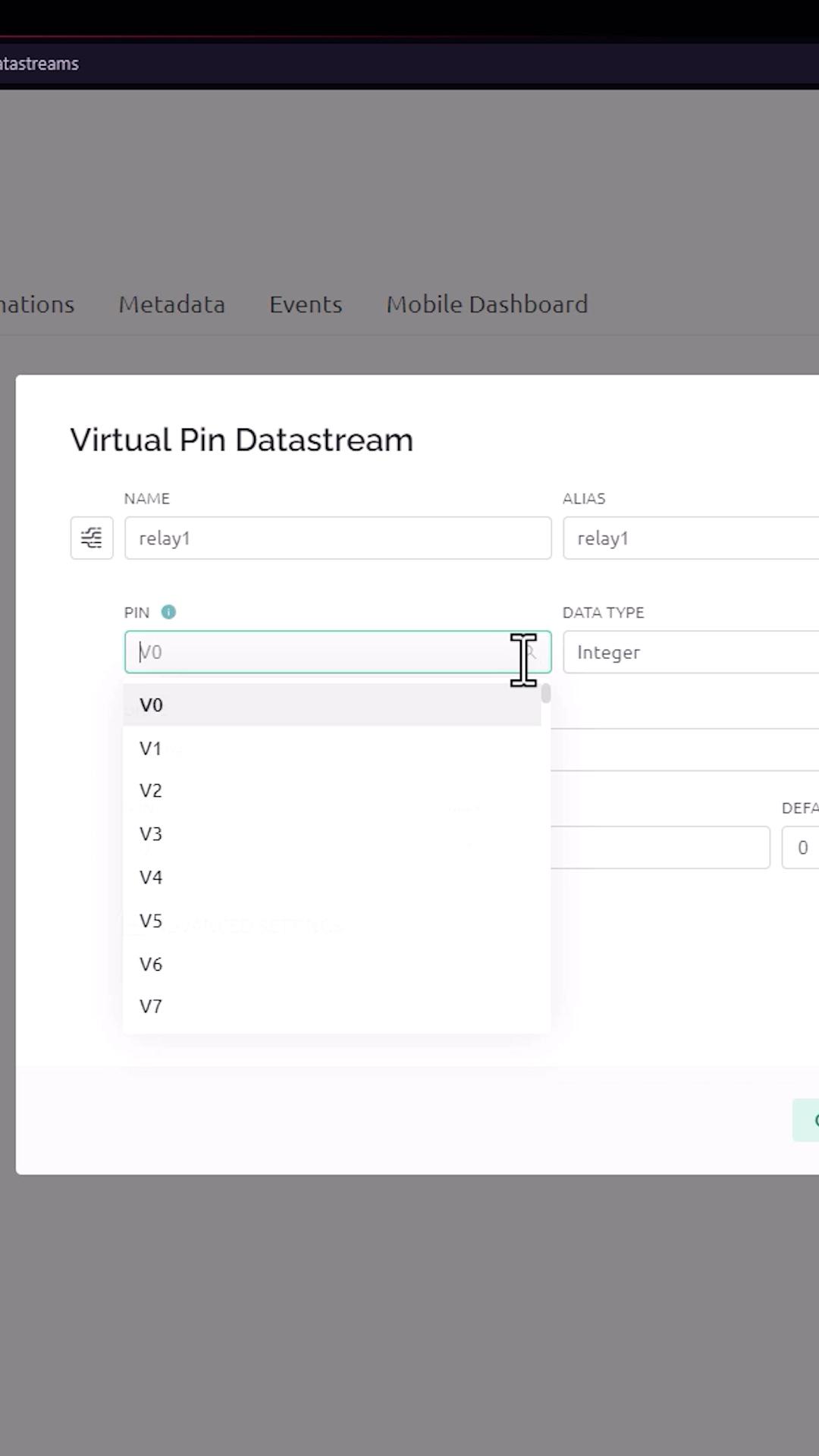
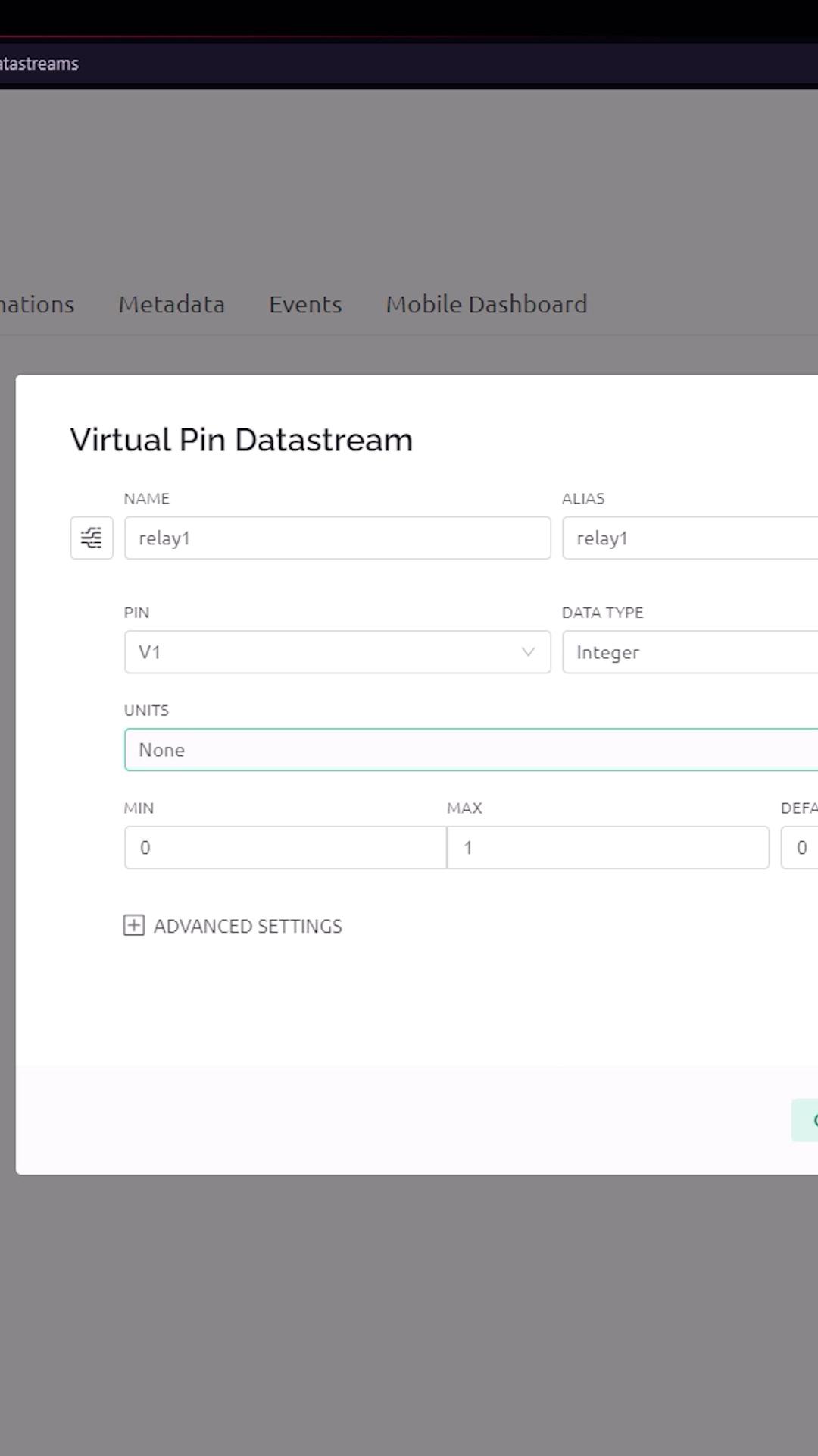
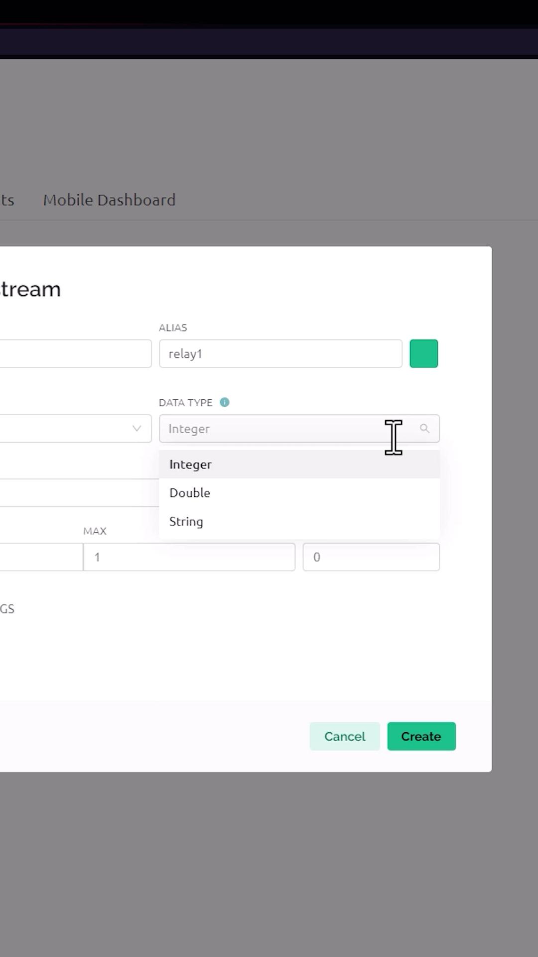
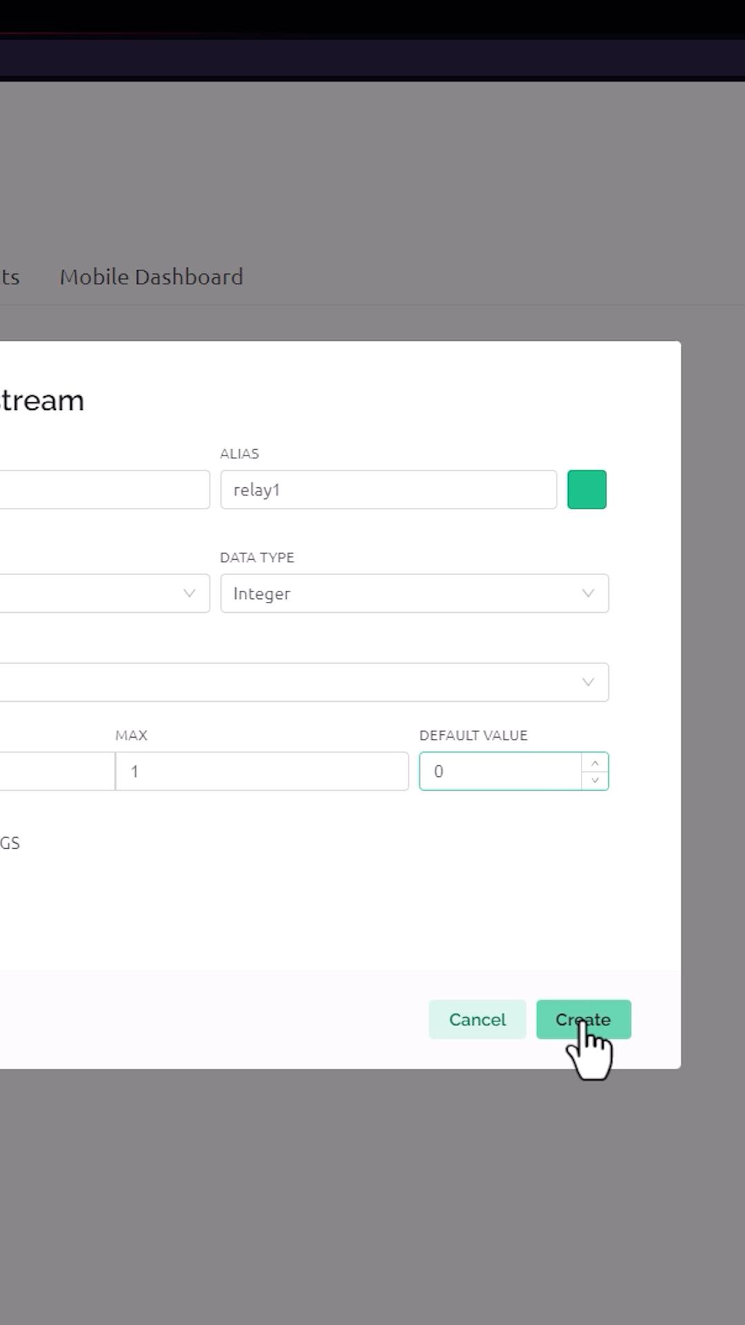
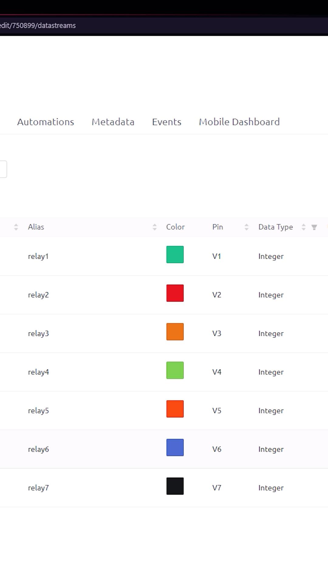
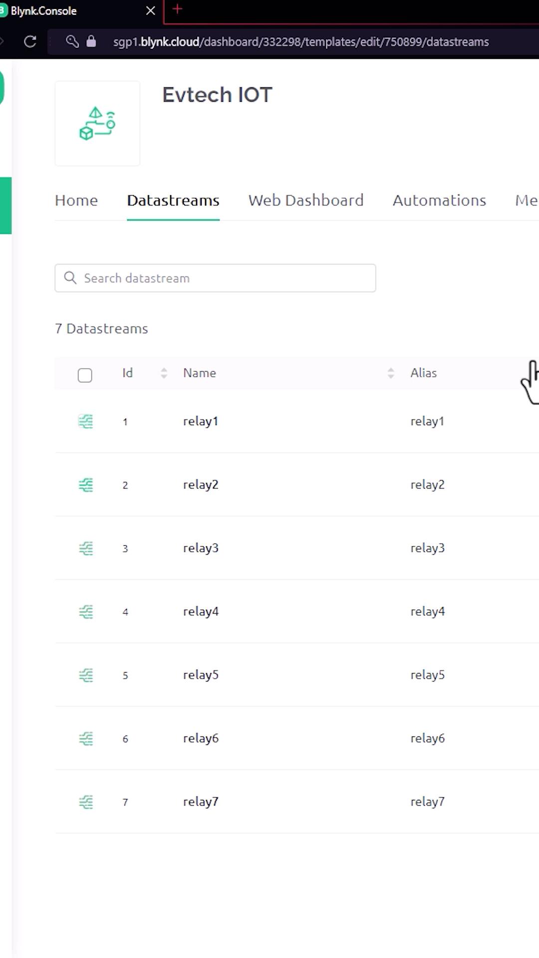
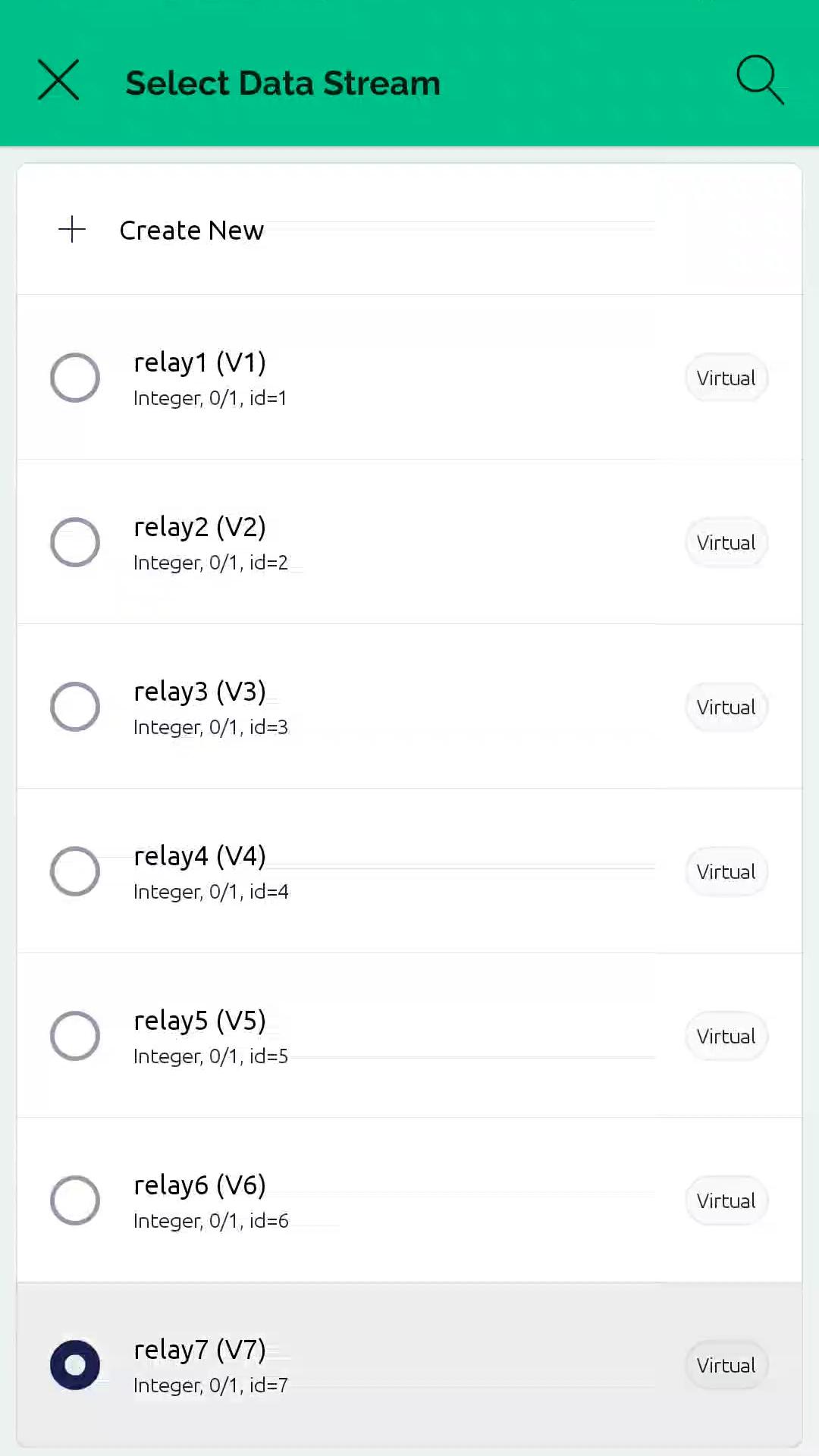
The template has now been created with the name Evtech IOT. Next is to go to the datastreams, after that click new datastreams, and then click virtual pin. In here, you need to enter the name as relay1, and select the virtual pin as V1, and select the data type as integer, and after that, click create. Do the same process six more times in order to create a total of seven data streams. Make sure to set the virtual pin from V1 to V7 and the data type to integer.
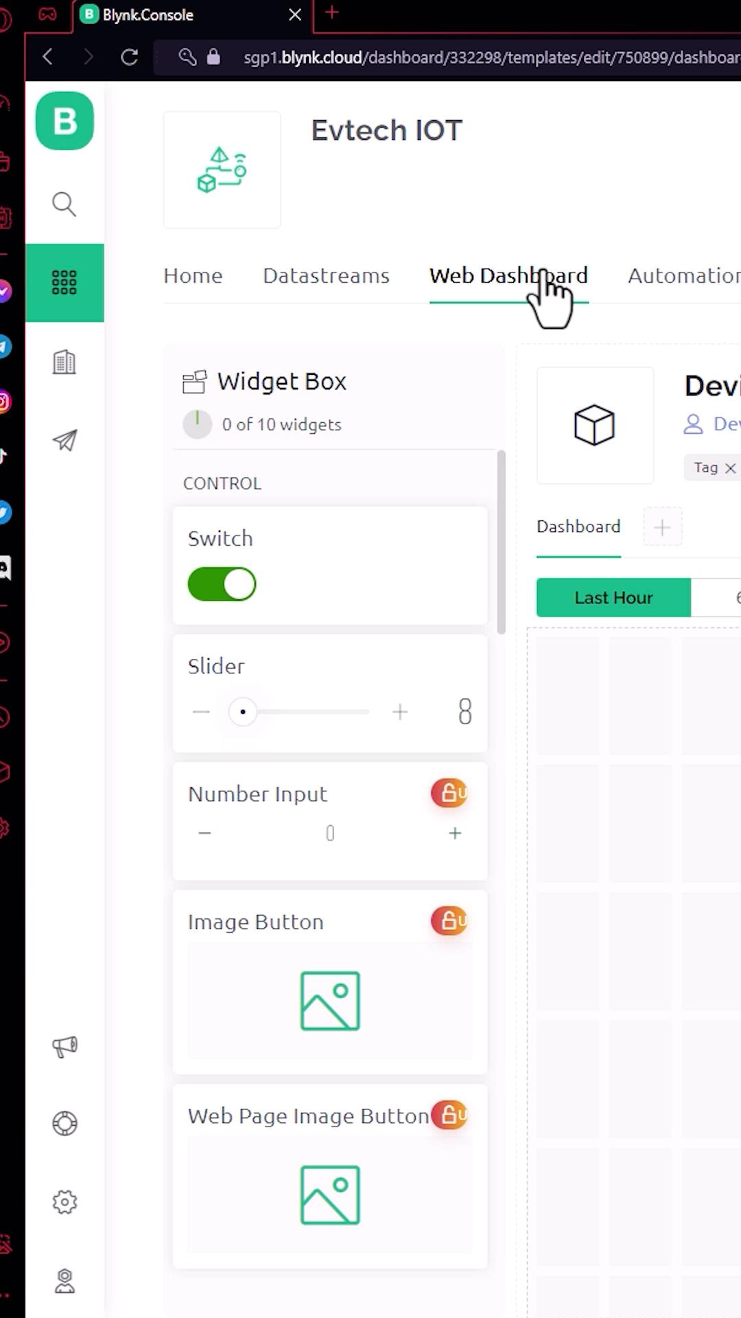
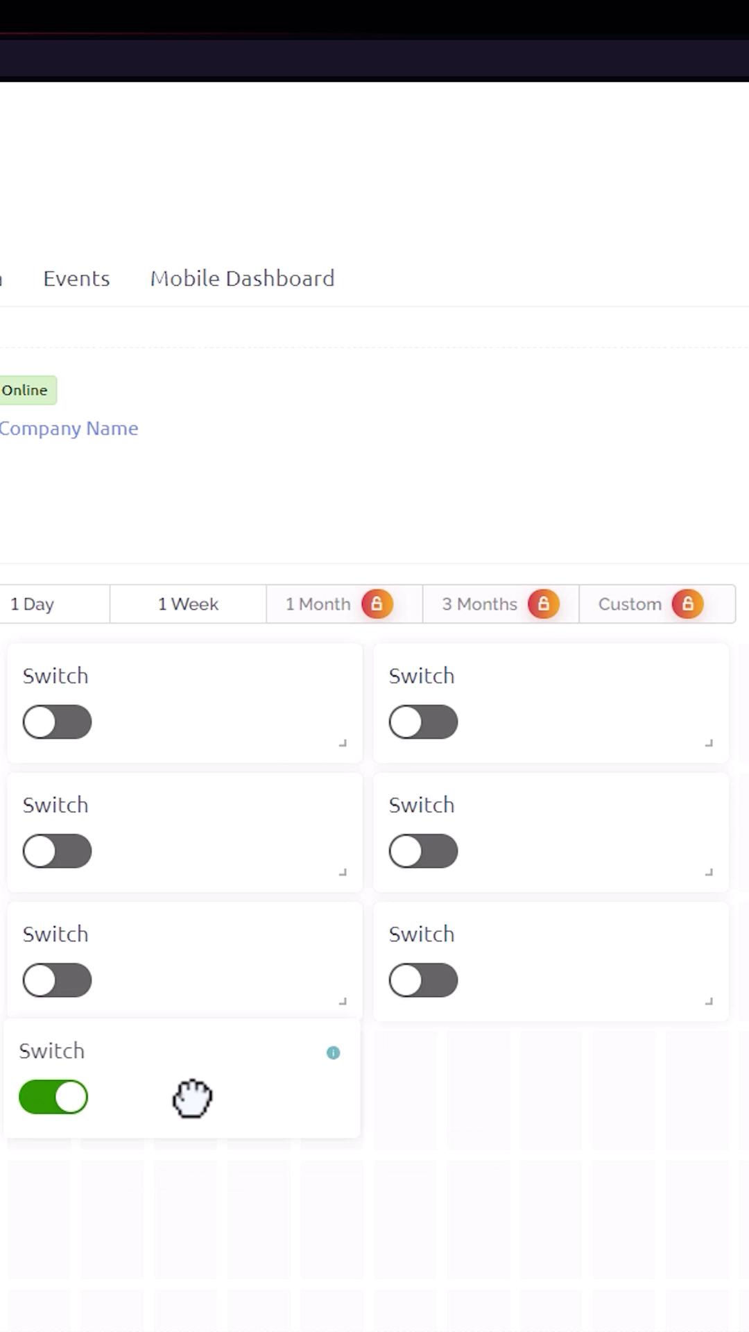
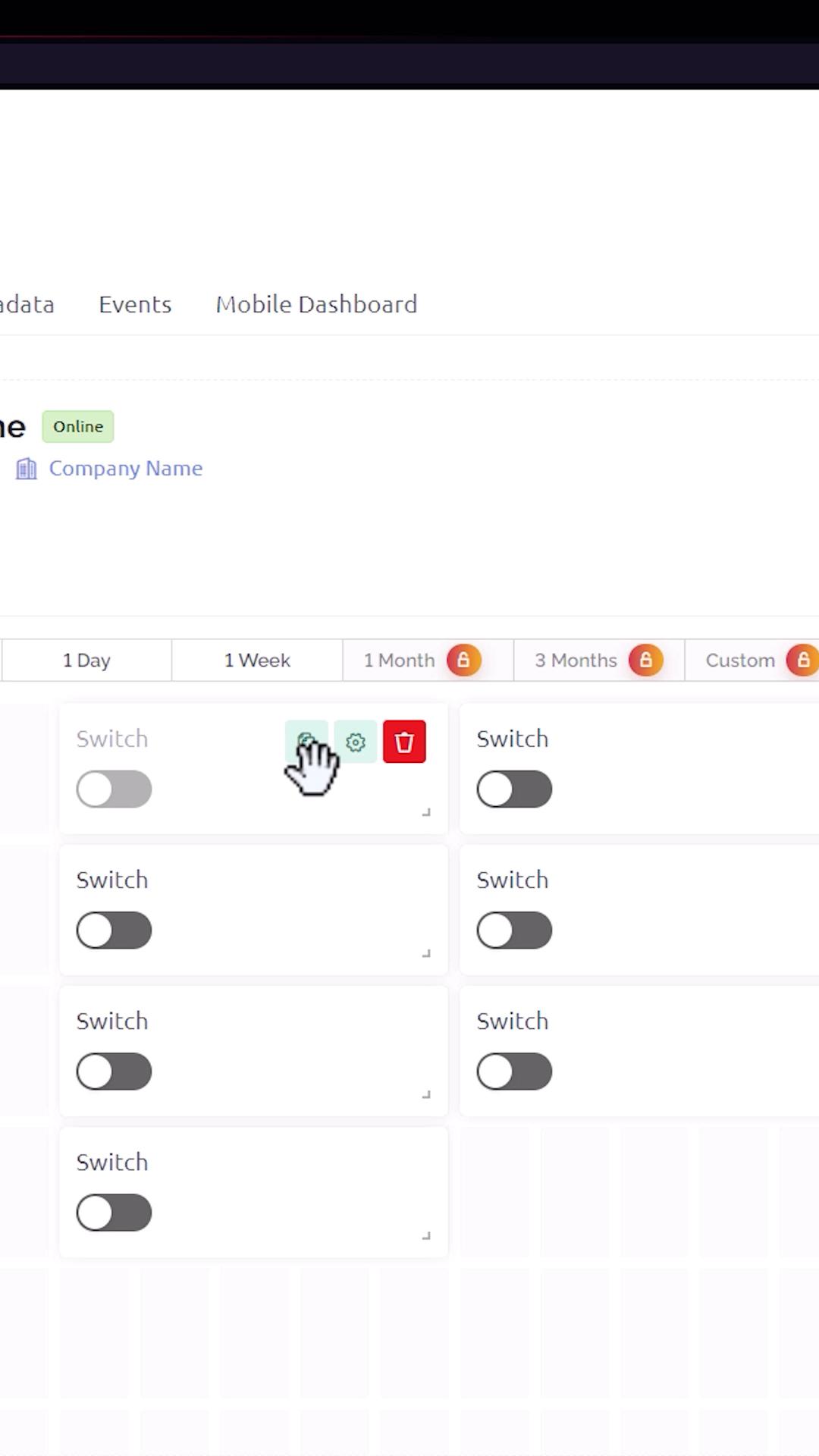
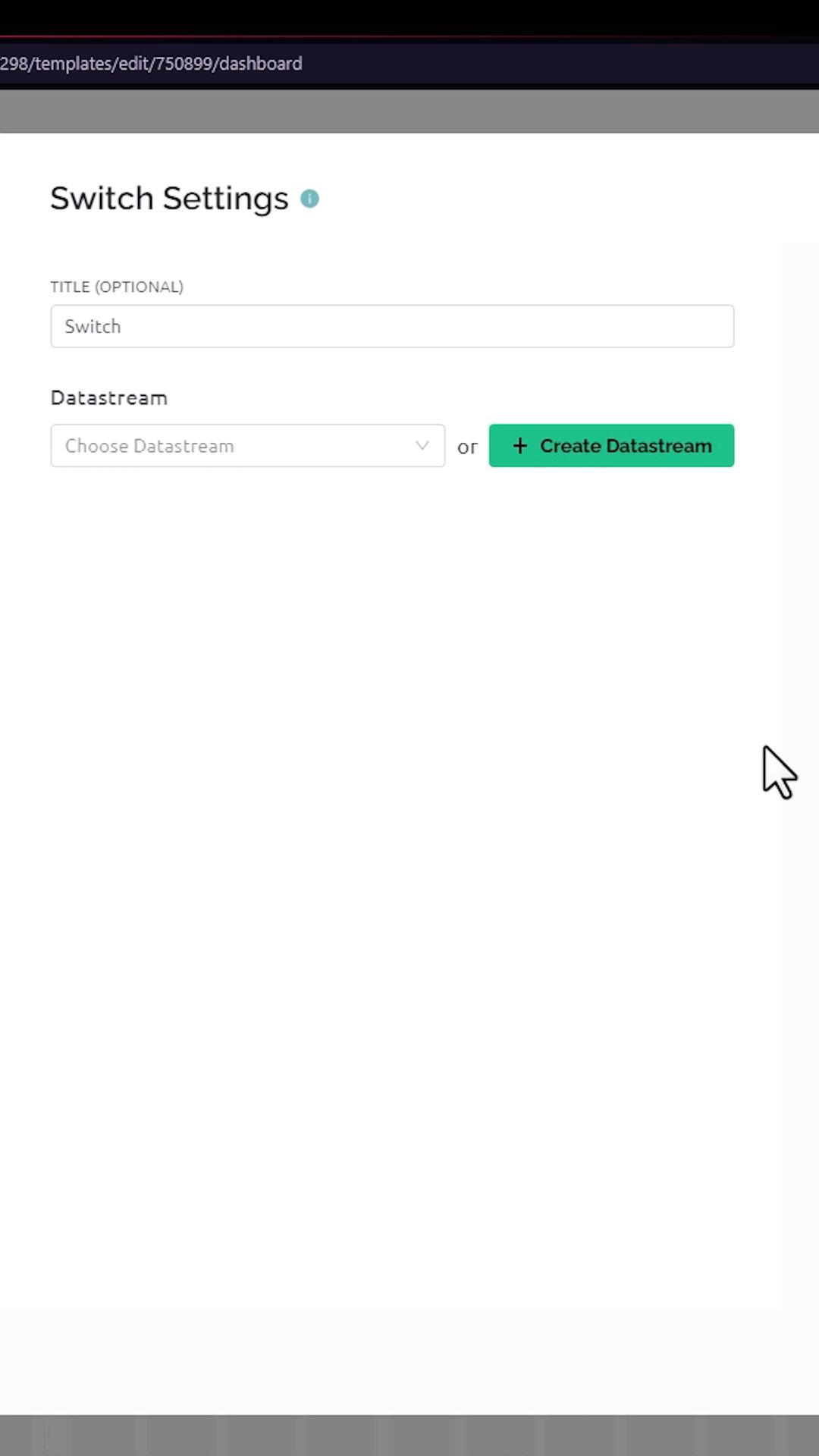
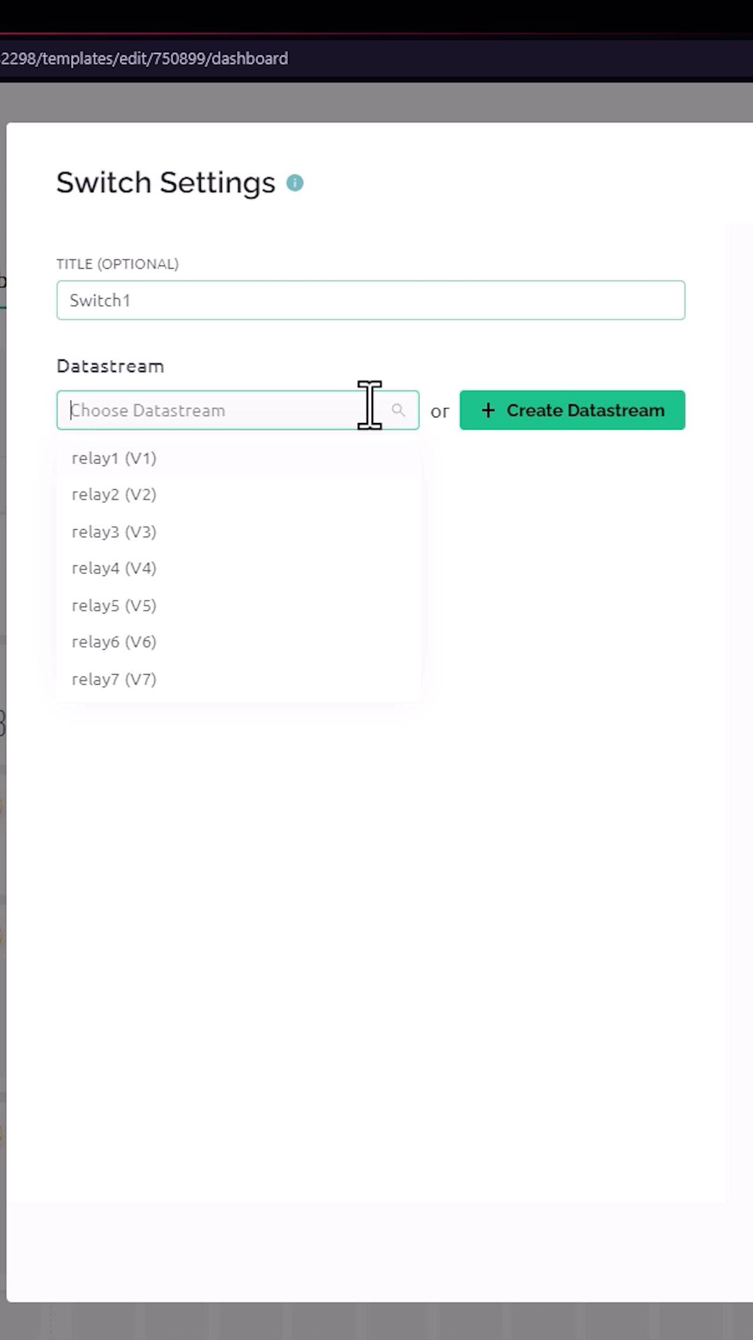
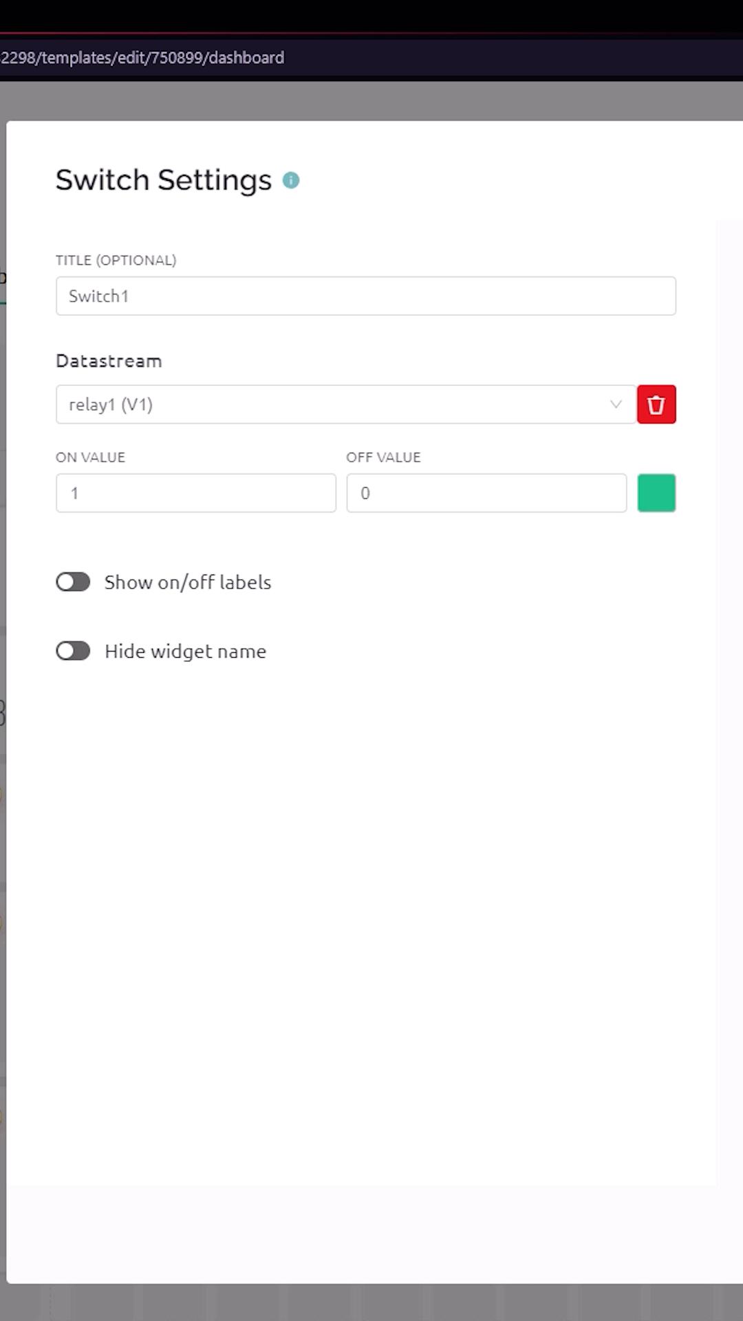
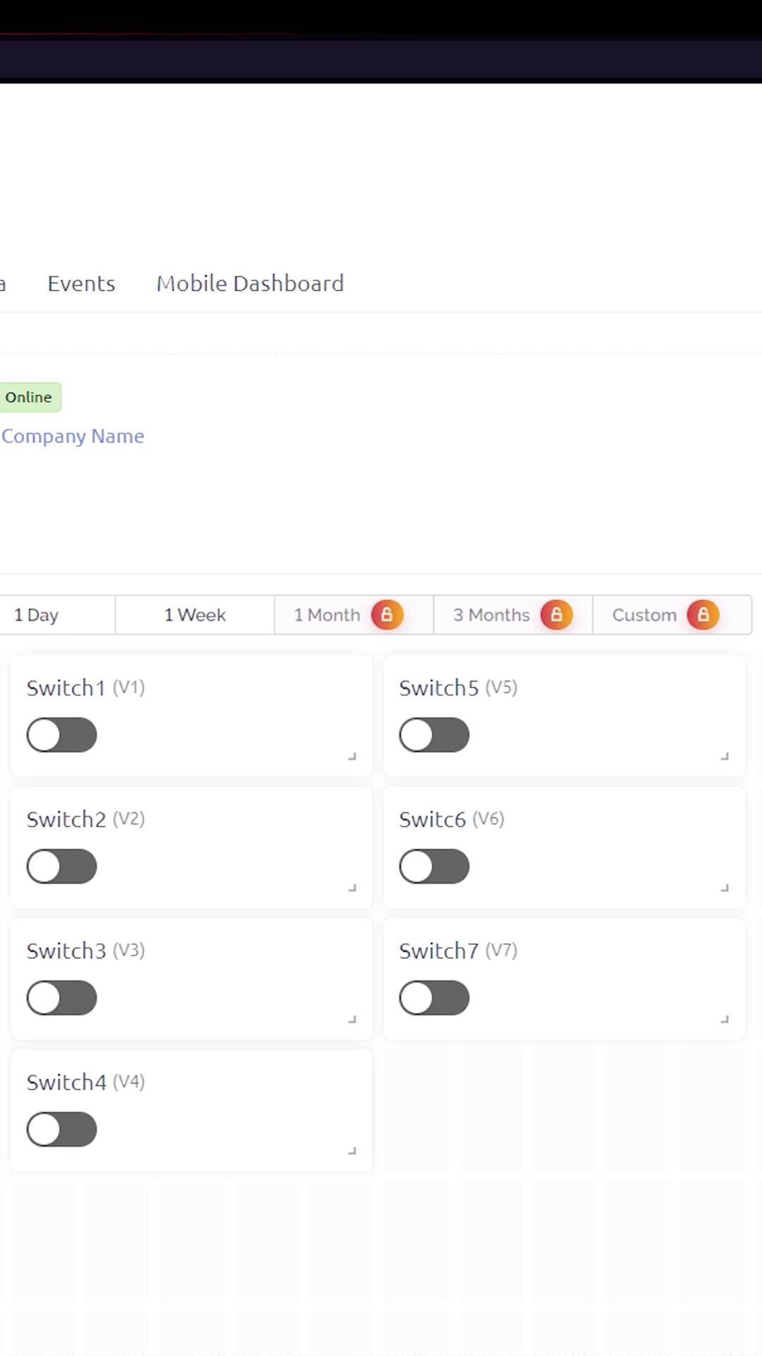
Next step is to create a web dashboard. In here, add 7 switches from the left panel. After that, click the setting of the first switch, and then enter the name for the switch as switch 1, and select the data stream as relay 1 (V1). After that, click the save button.
Do the same process for the six switches, make sure to set the appropriate datastream on each switch. Now click the Save button to save the template.
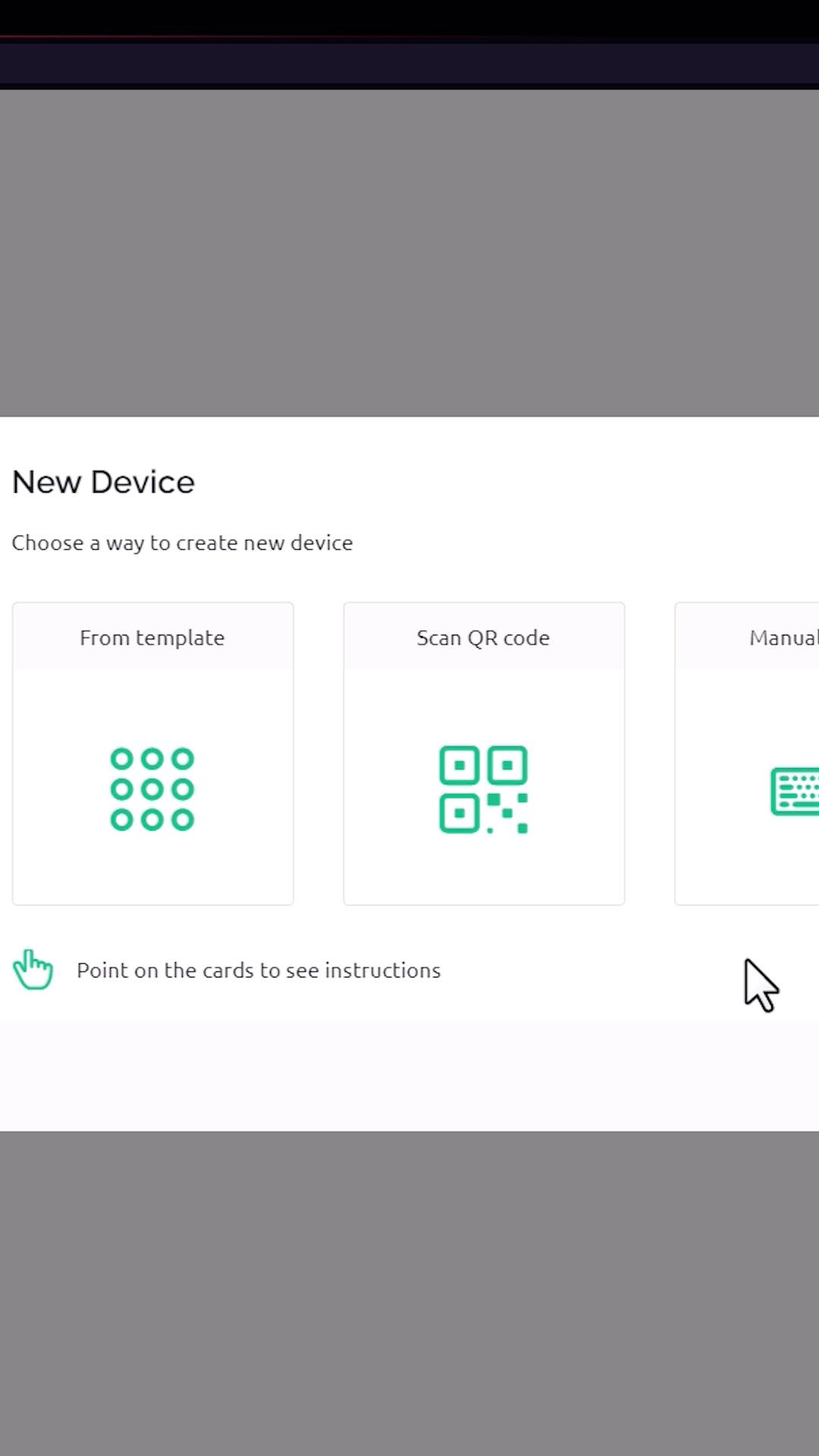
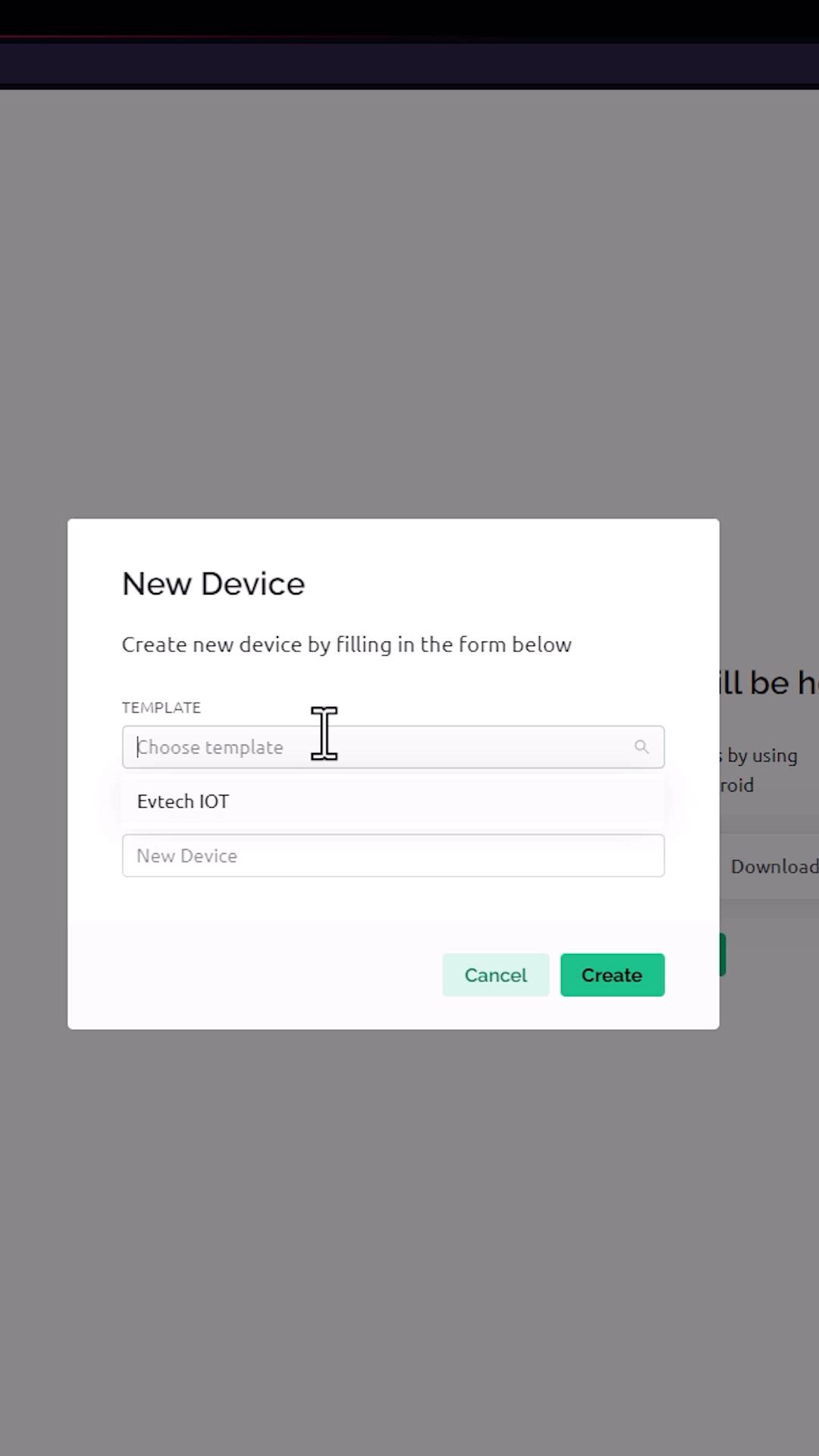
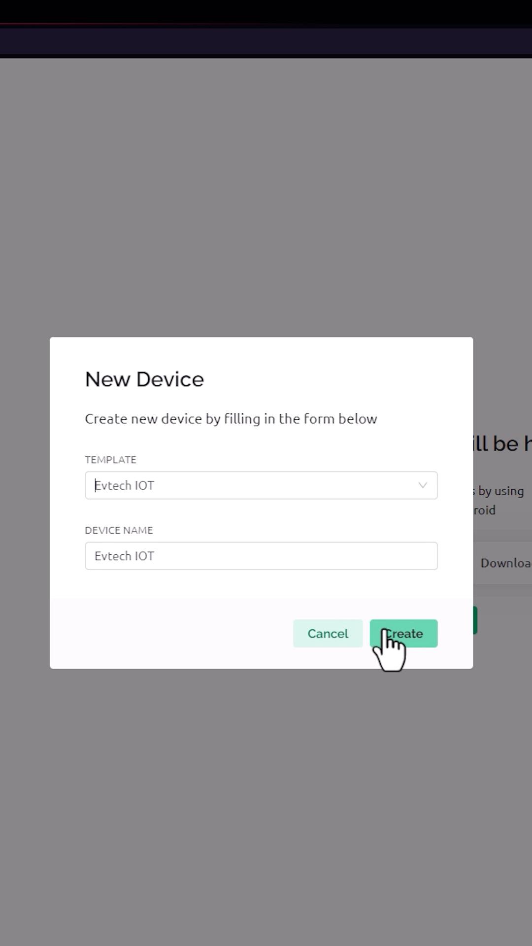
Next is to add a device. You can add a device by clicking this button and then selecting from the template. In here, select the template that we created before, in my case, Evtech IOT, and then click the create button.
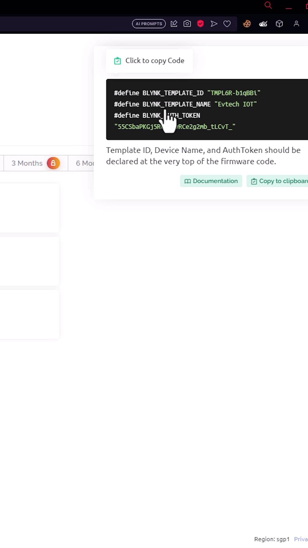
As you can see here, after I click the create button, it creates credentials, which we will put inside the Arduino code.
Setting Up Arduino
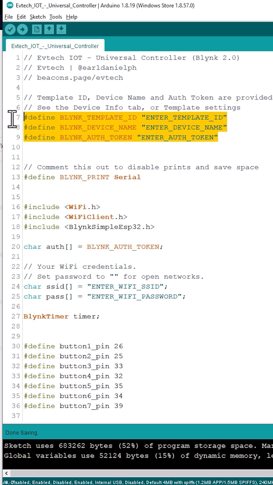
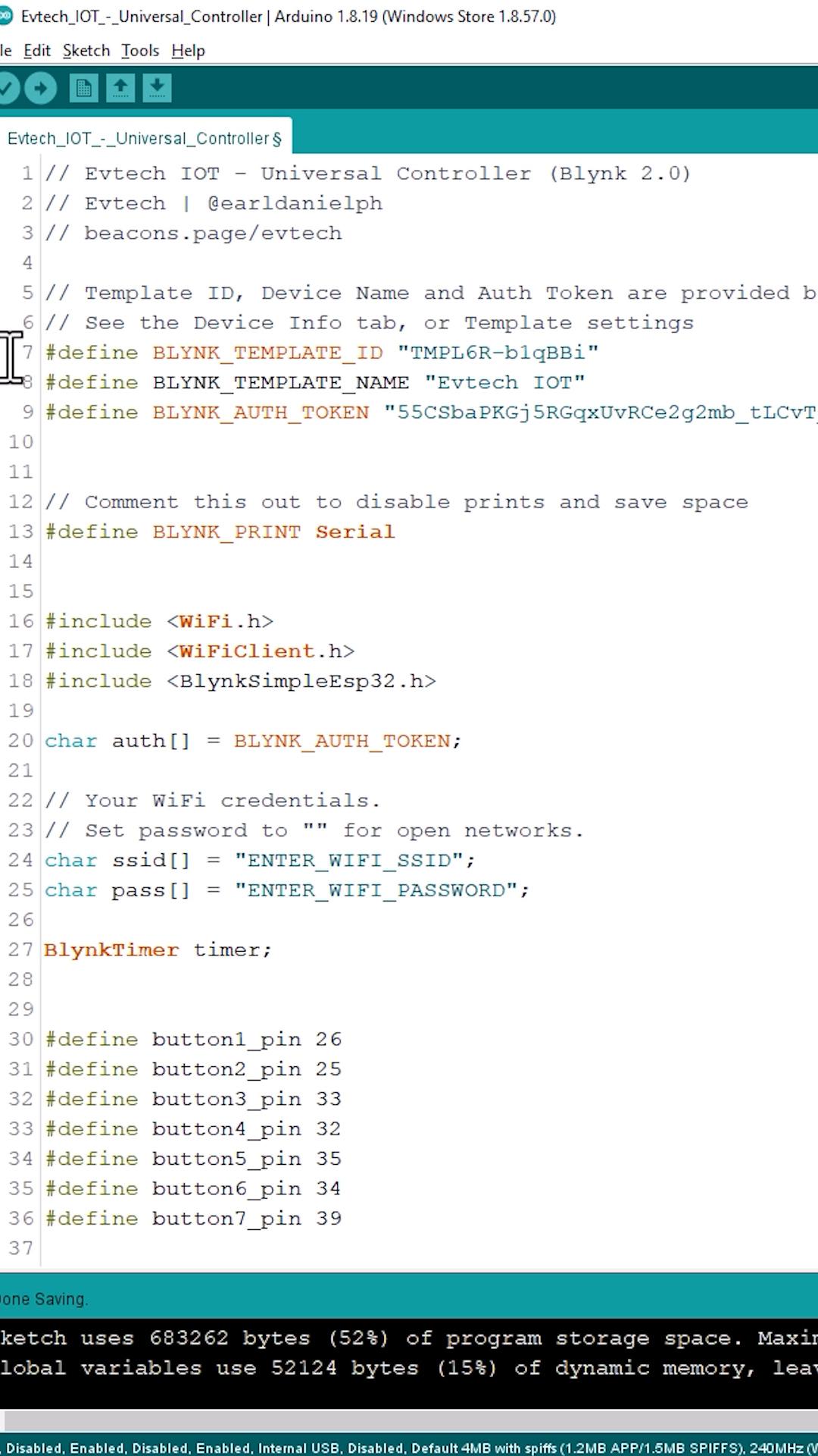
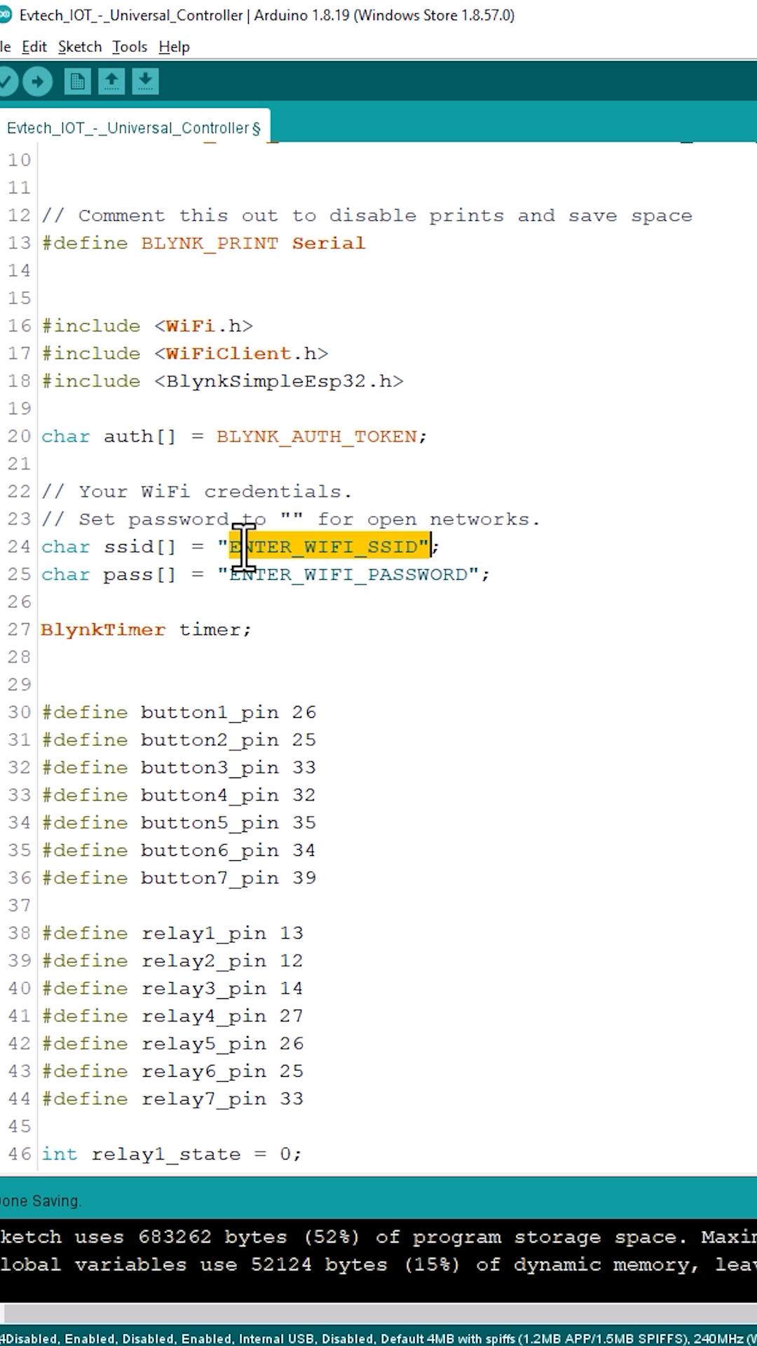
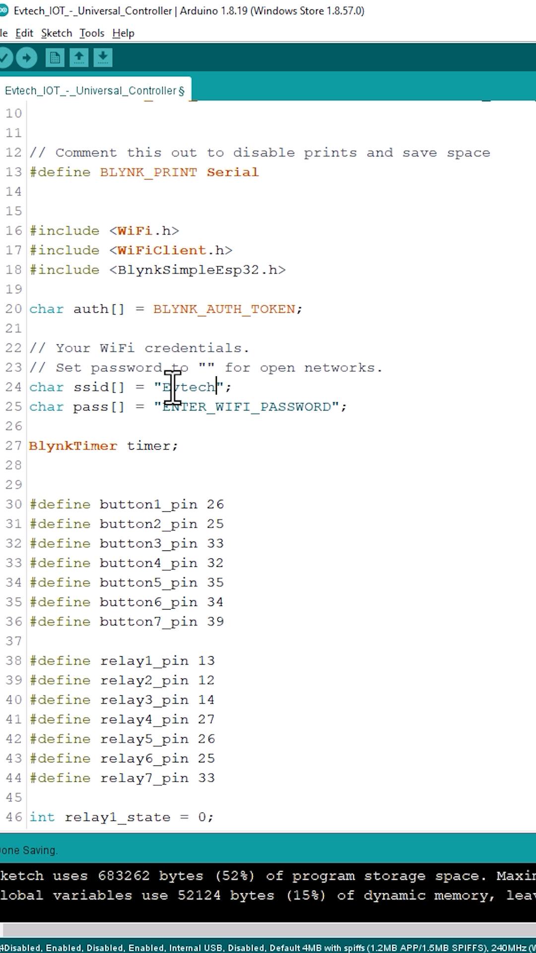
Copy the code and paste it into the Arduino sketch file. Next, go to this line and enter your Wi-Fi credentials.
You can download this code by clicking the beacons link in my bio; after that, it will direct you to all my social media links, and in there you can see my github; click it and download the Evtech IOT Universal Controller code. Everything you need is in the file package. This includes the parts placement diagram, the wiring diagram, the Gerber files, the PCB layout, and the Arduino code.
GitHub Link: (https://bit.ly/3NRA8nP)
Now, click the upload button to upload the Arduino code to the ESP32 board. Once done, open the serial monitor to check the ESP32 connection status.
Setting Up Blynk App Dashboard
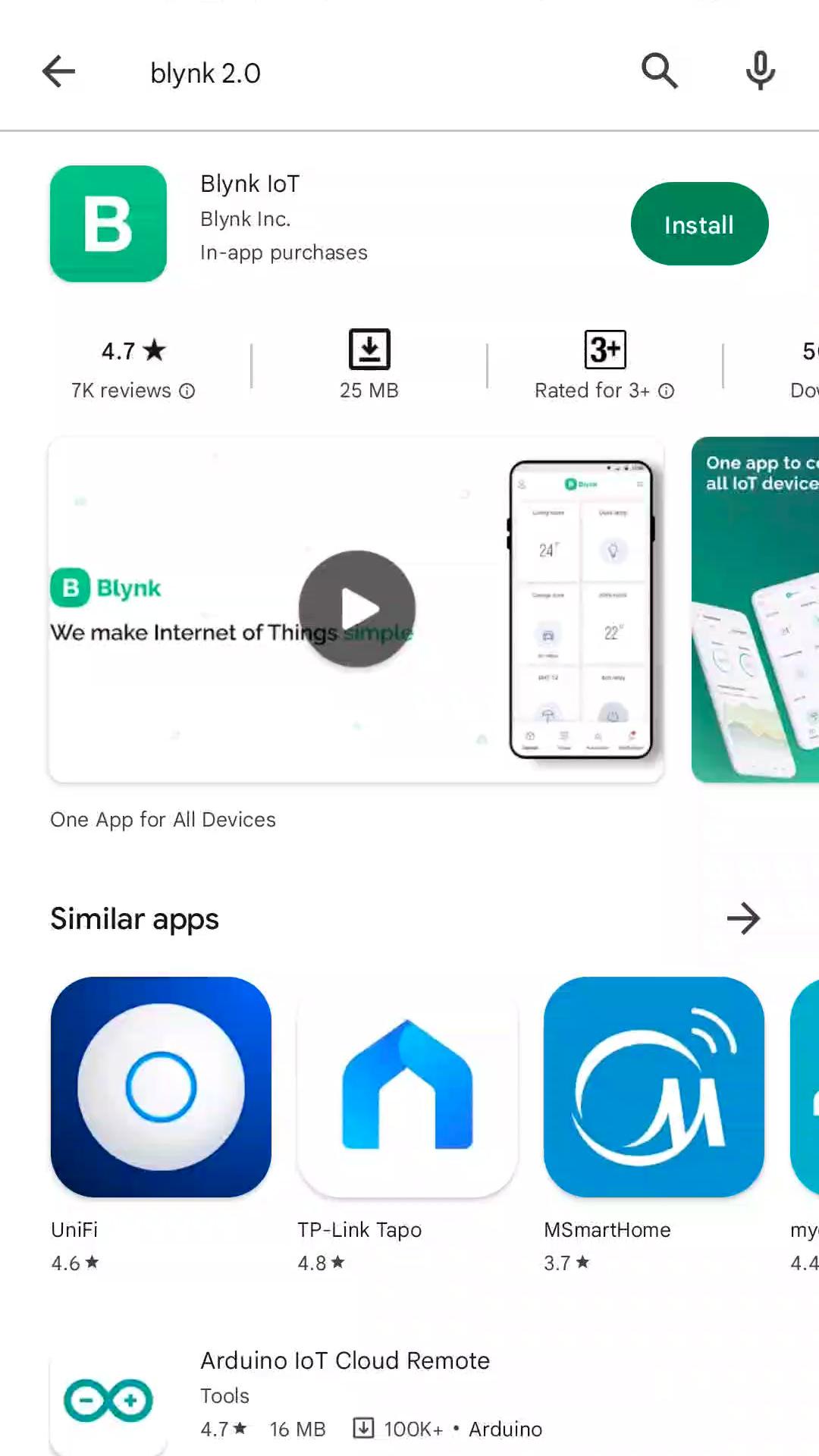
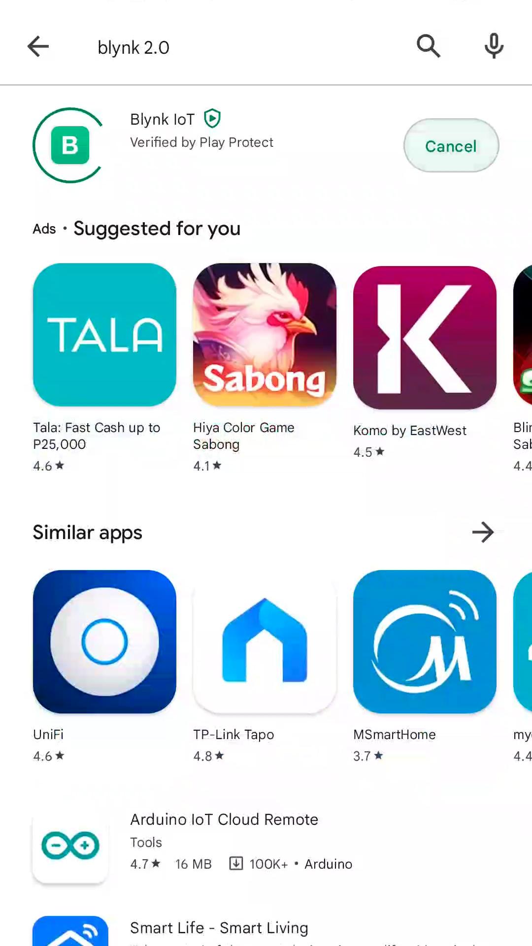
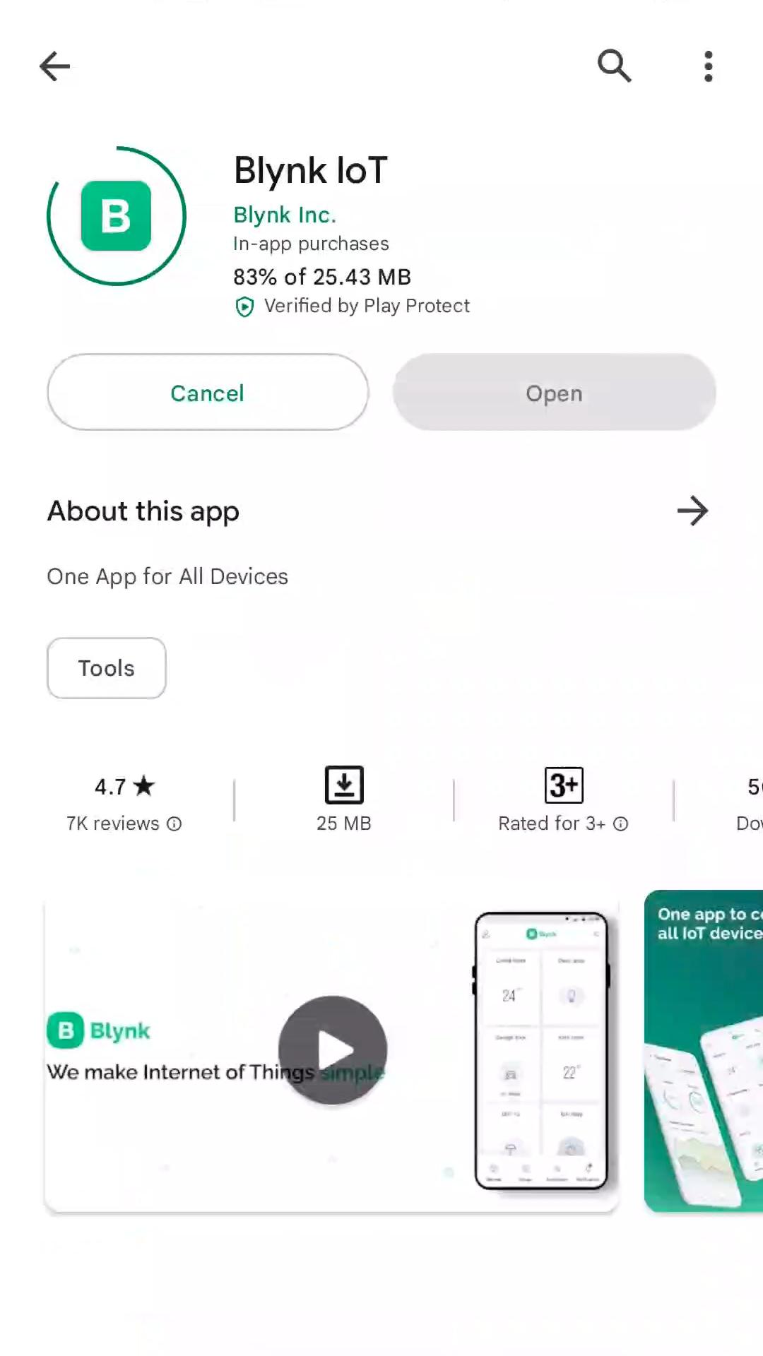
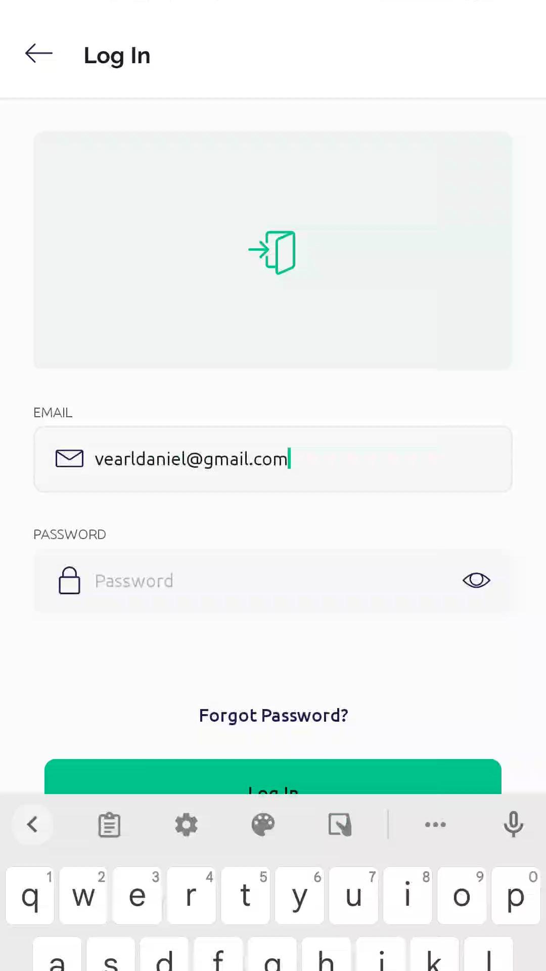
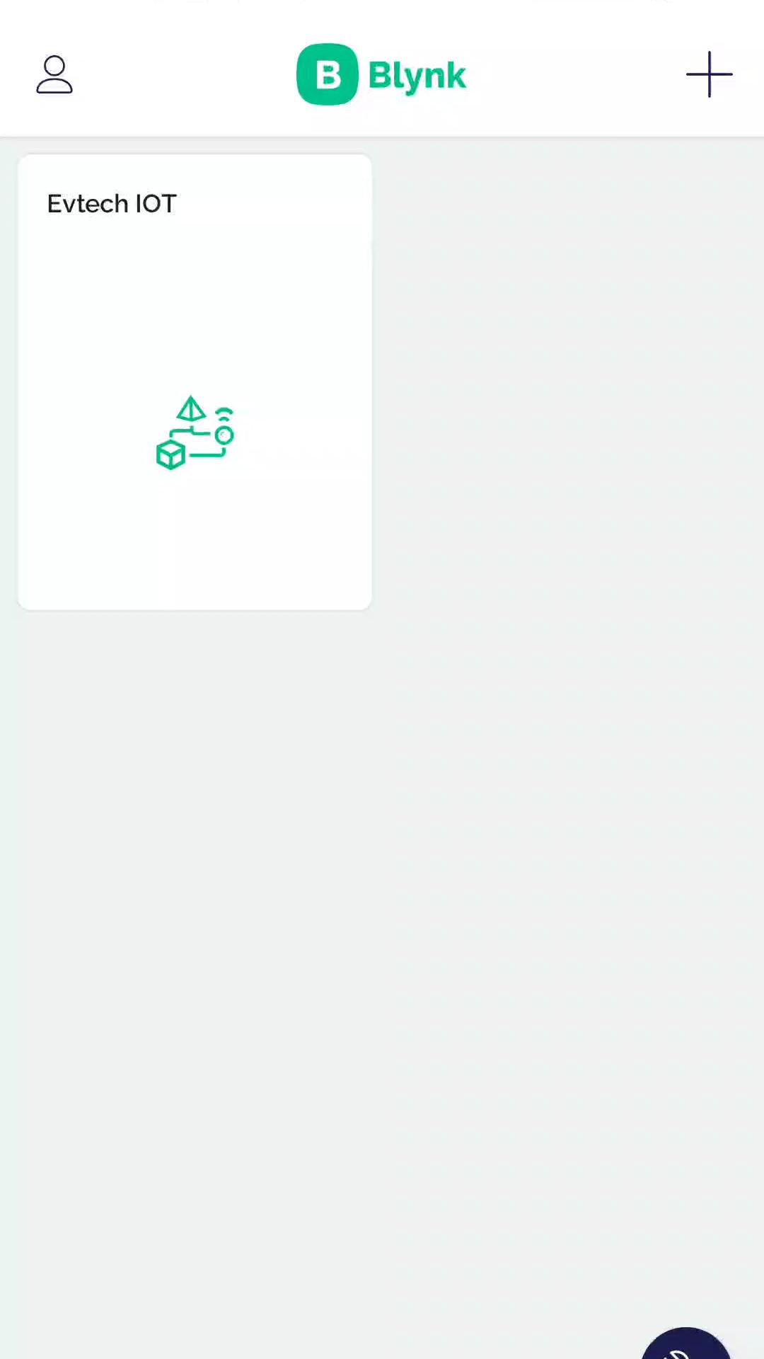
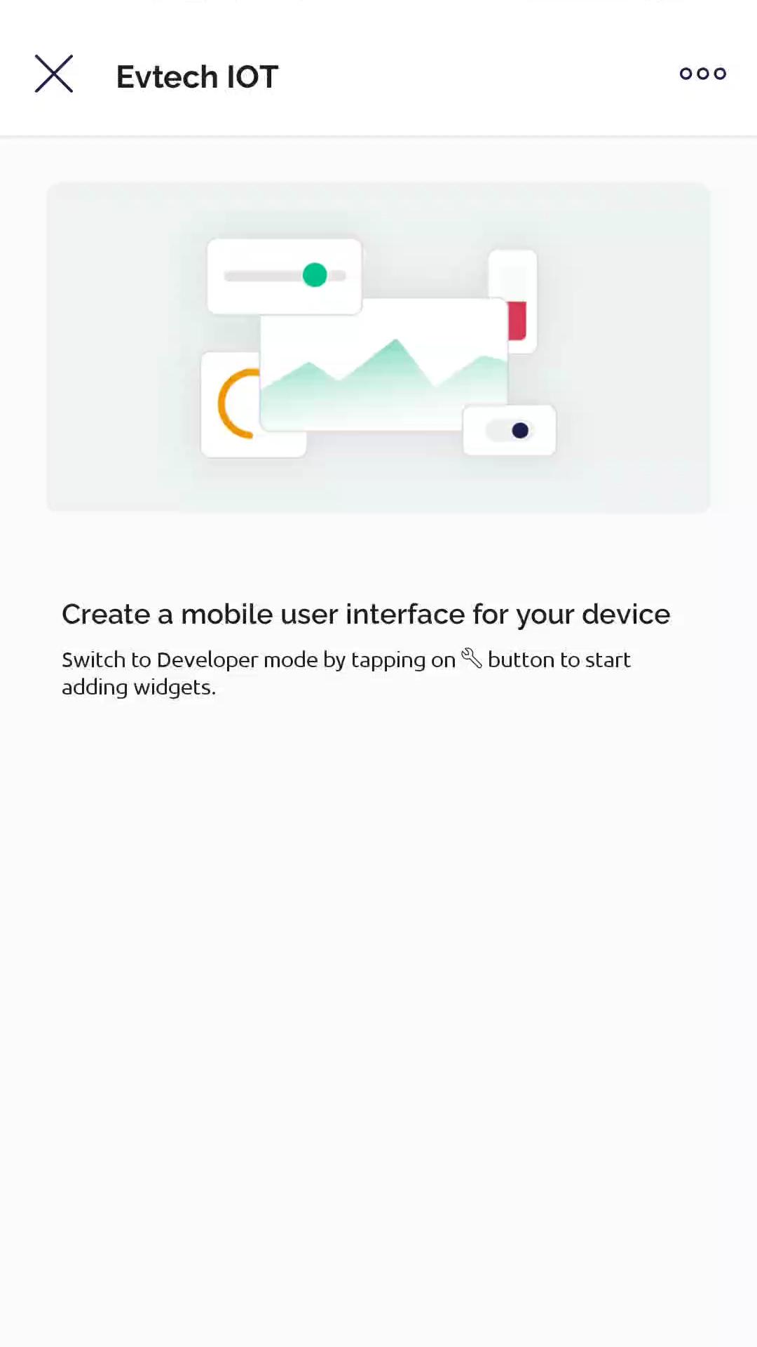
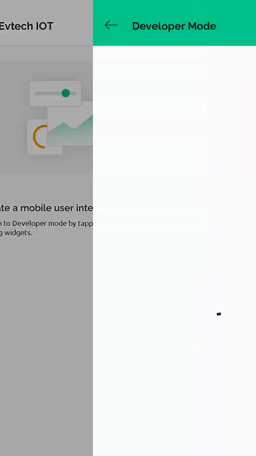
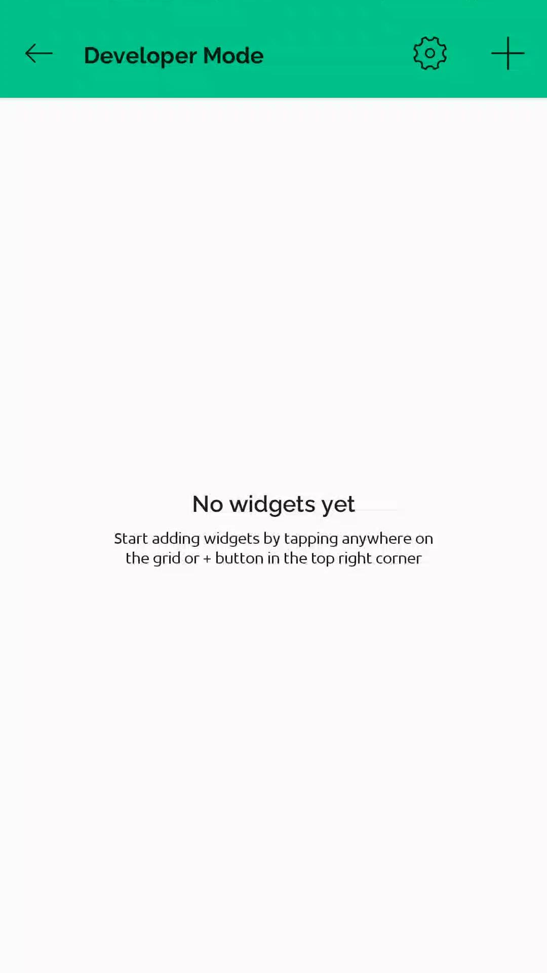
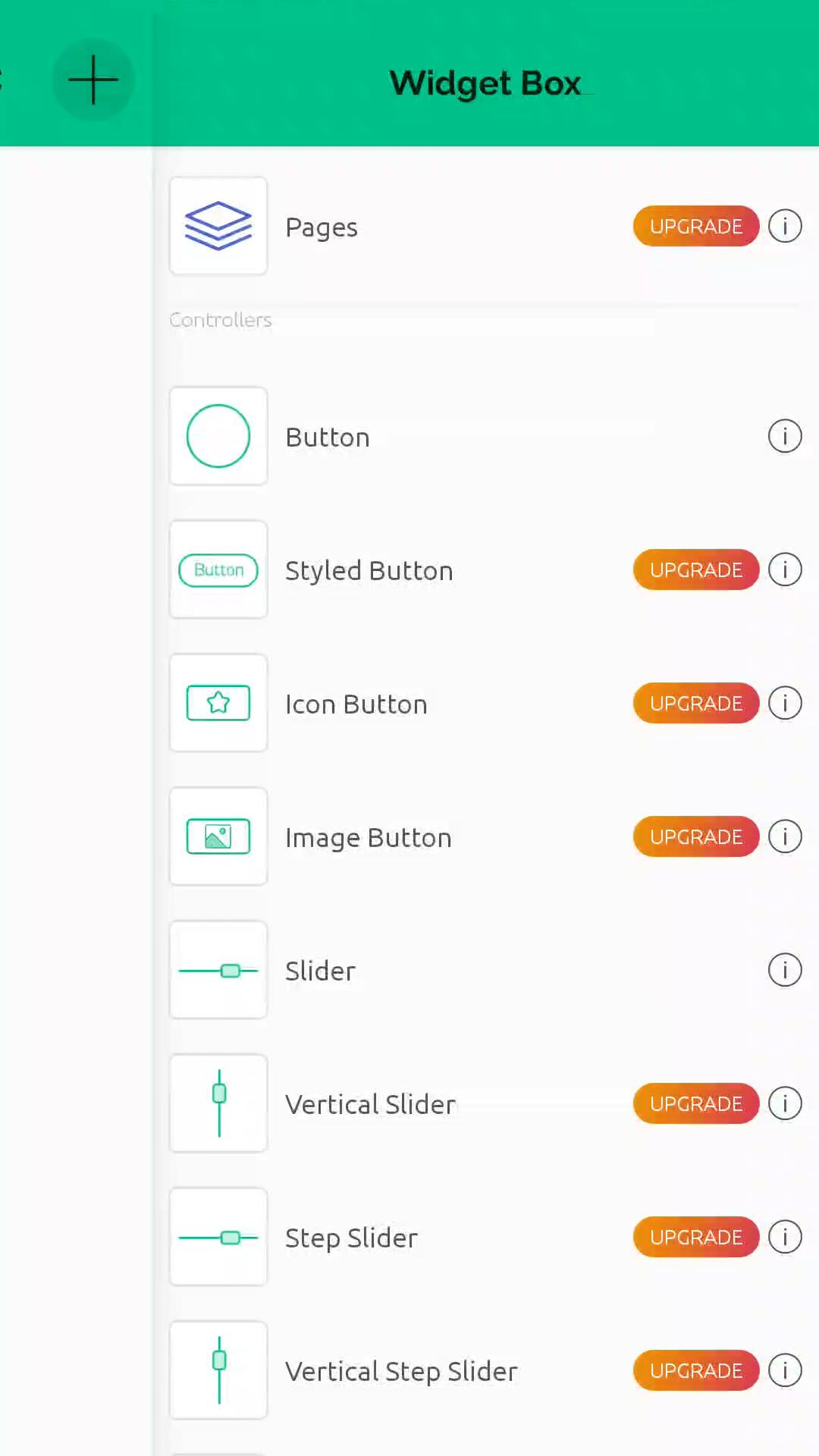
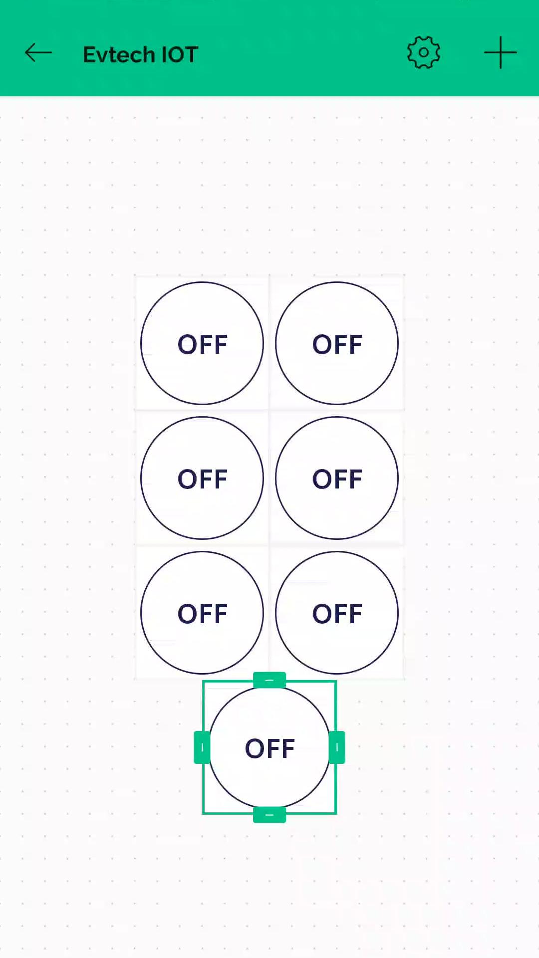
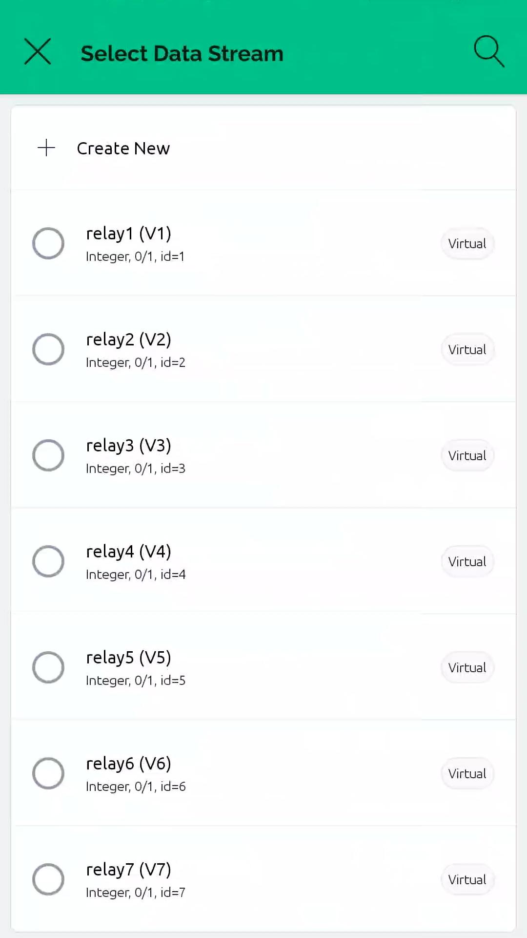
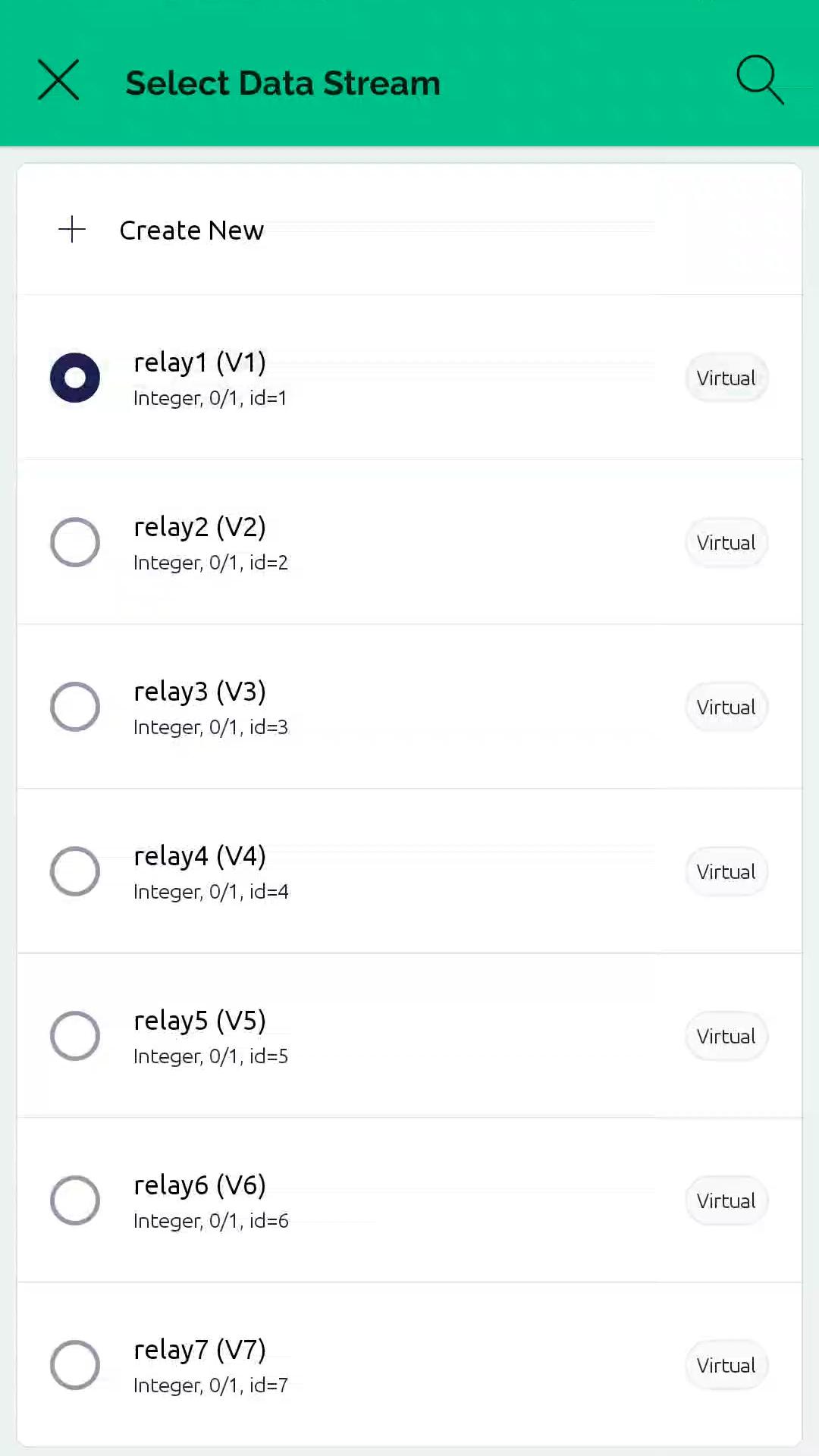
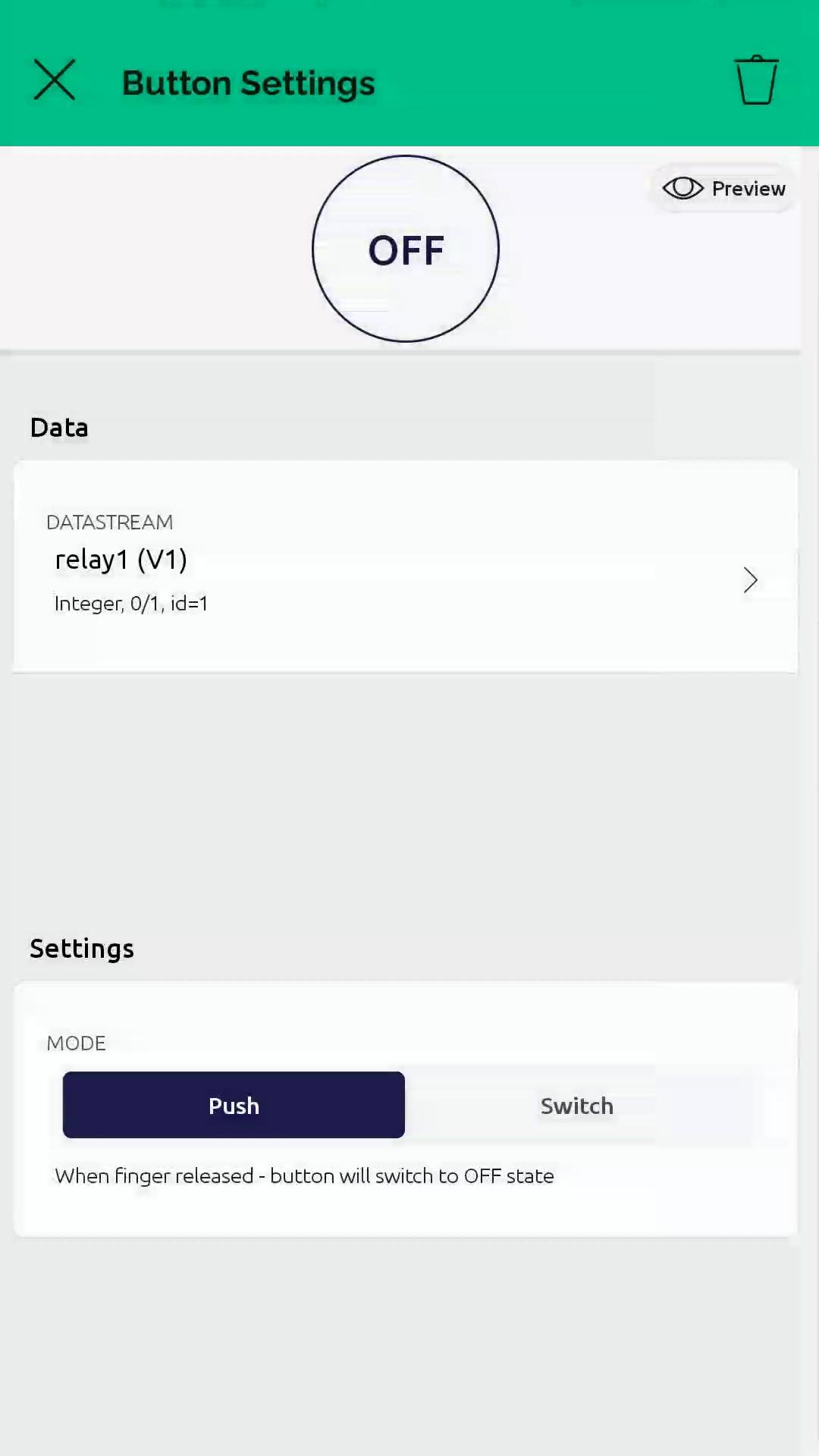
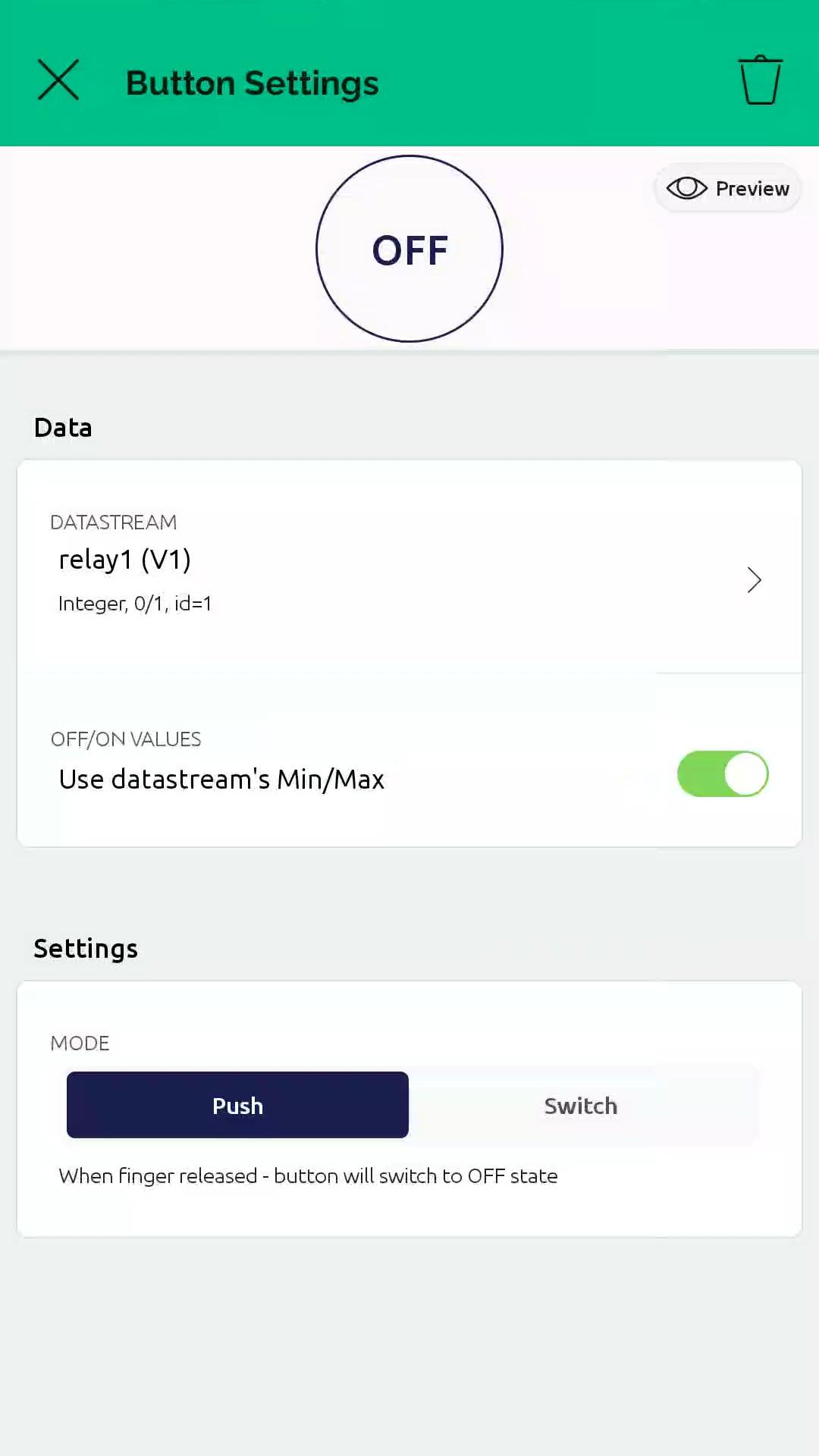
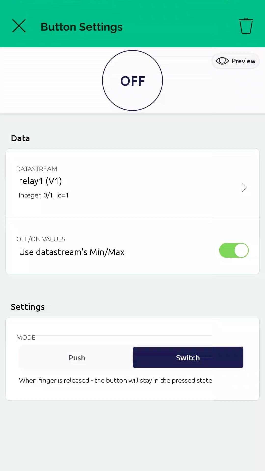
Next step is to install the Blynk app on your mobile phone to create a mobile dashboard. Search for Blynk 2.0 from the Play Store, and then install the Blynk IOT app. After the installation is complete, open the Blynk app. Here, log in with the same email that you used to create your account. Next, select the device that you created. Now, click this button to start adding widgets. After that, add 7 buttons here to control the 7 relays. Tap the first button, and then select datastream as relay1 (V1). Change the button mode to switch. Do the same process six more times and configure it from V2 to V7.
And there you have it! We have successfully configured the Blynk app dashboard!
Wire Them Up!
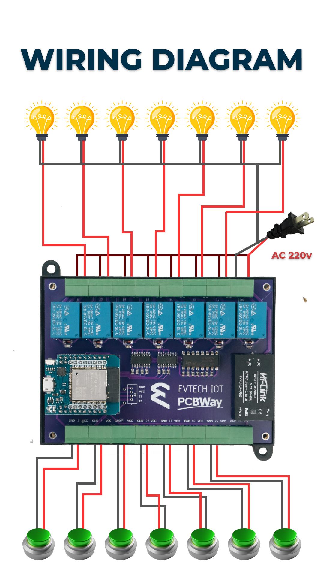
The last thing that we need to do is connect the electronic devices, which in my case are two bulbs, to test this project.
Enjoy!

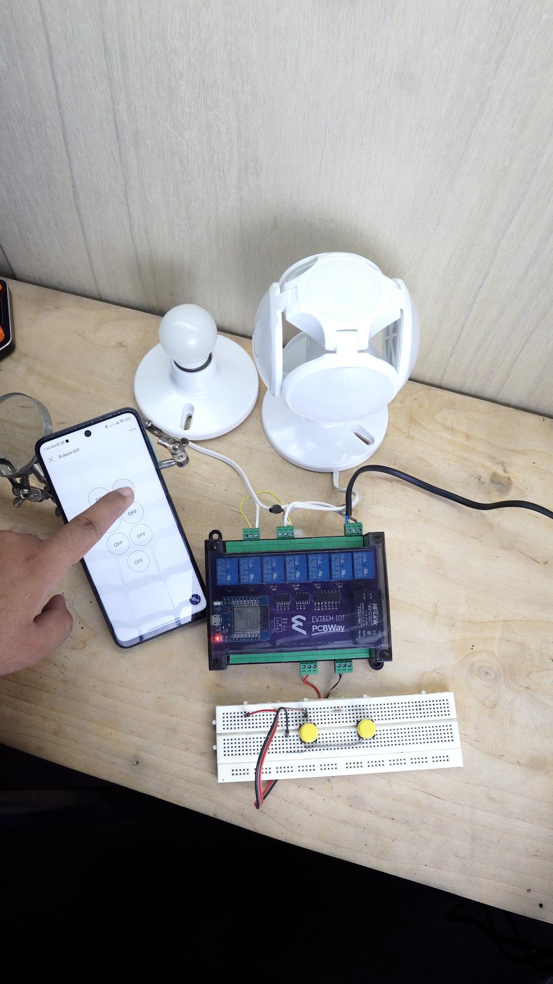
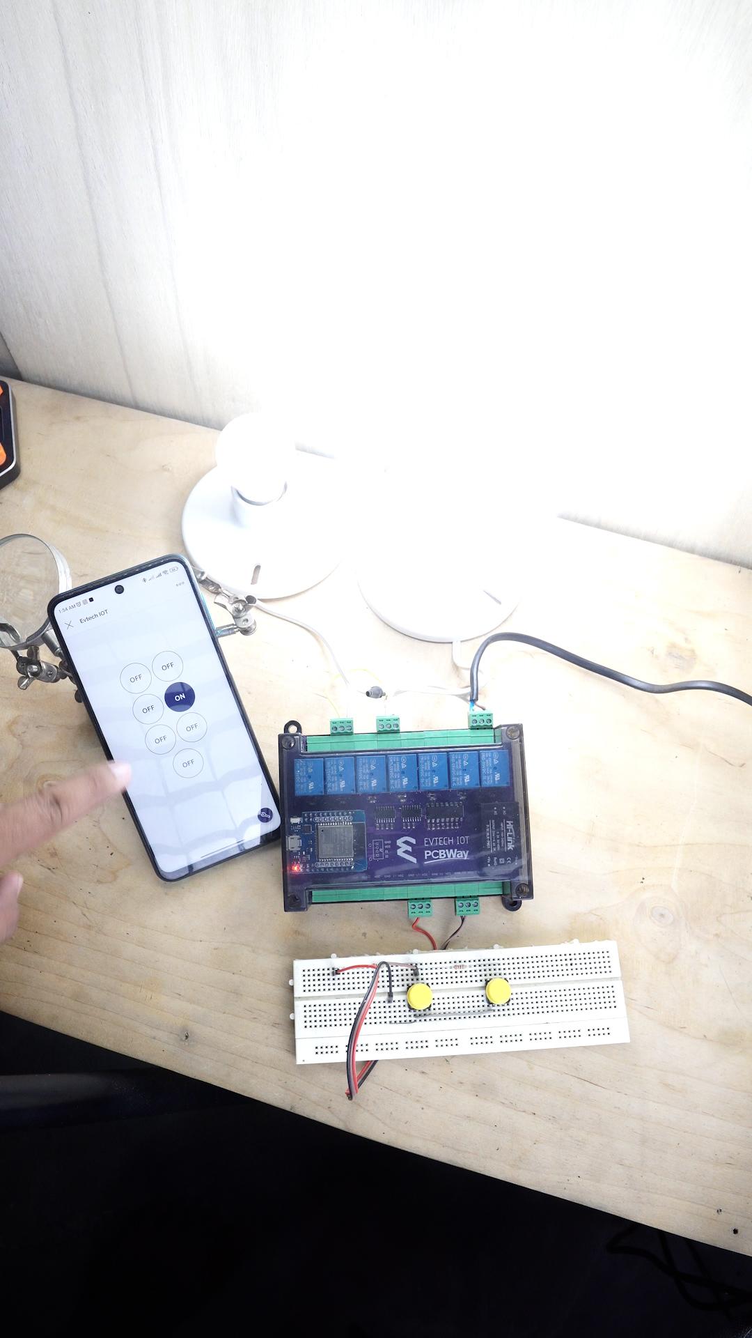
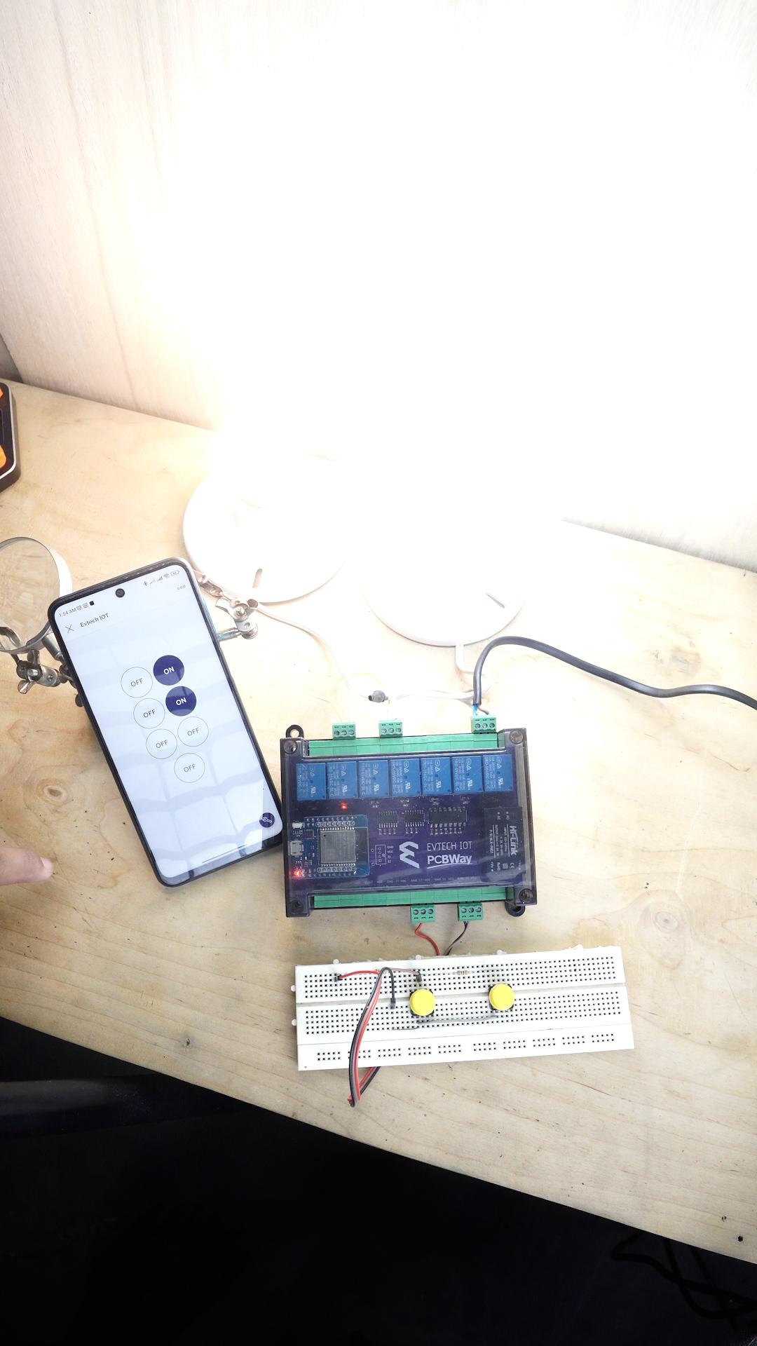
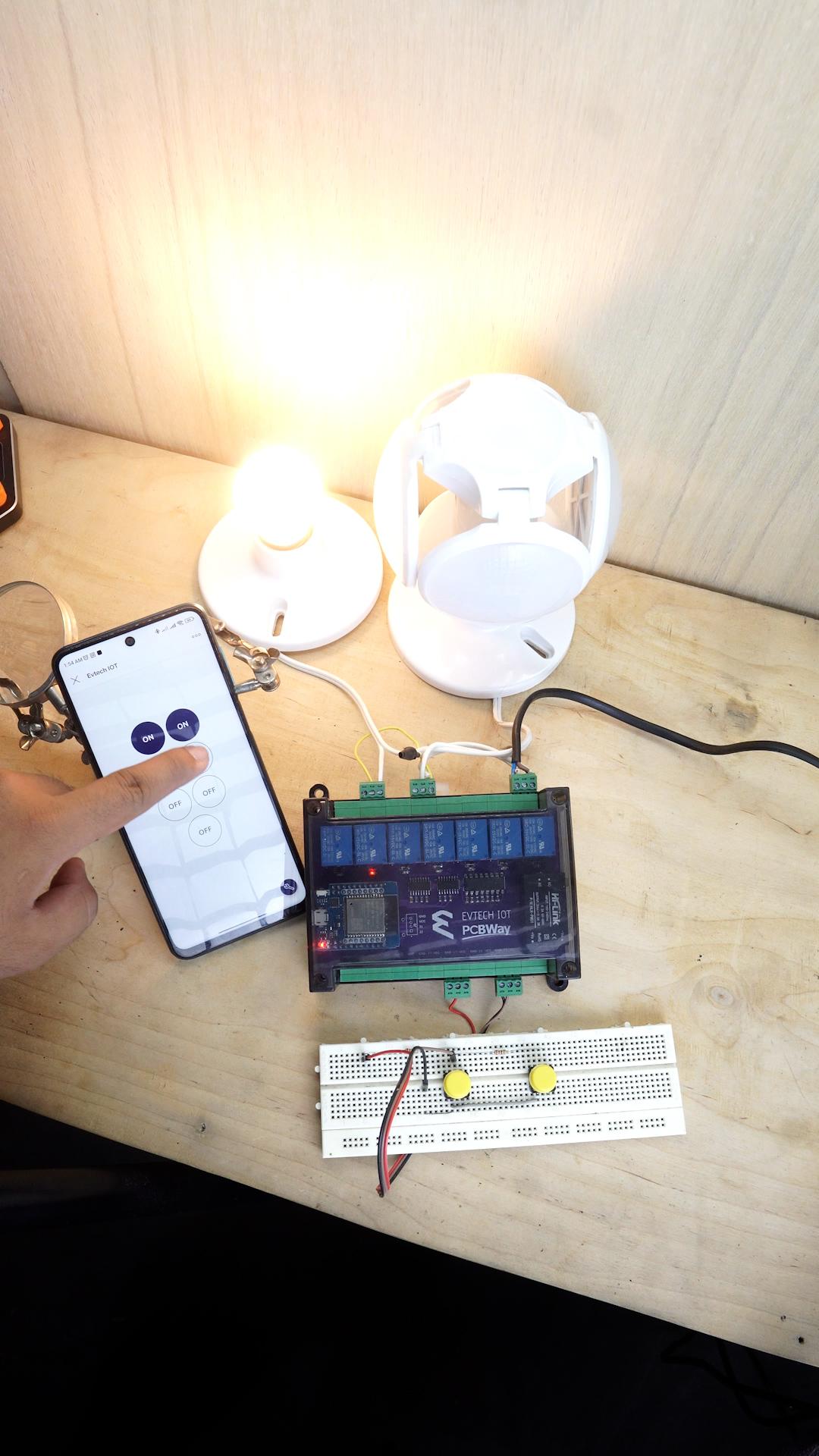
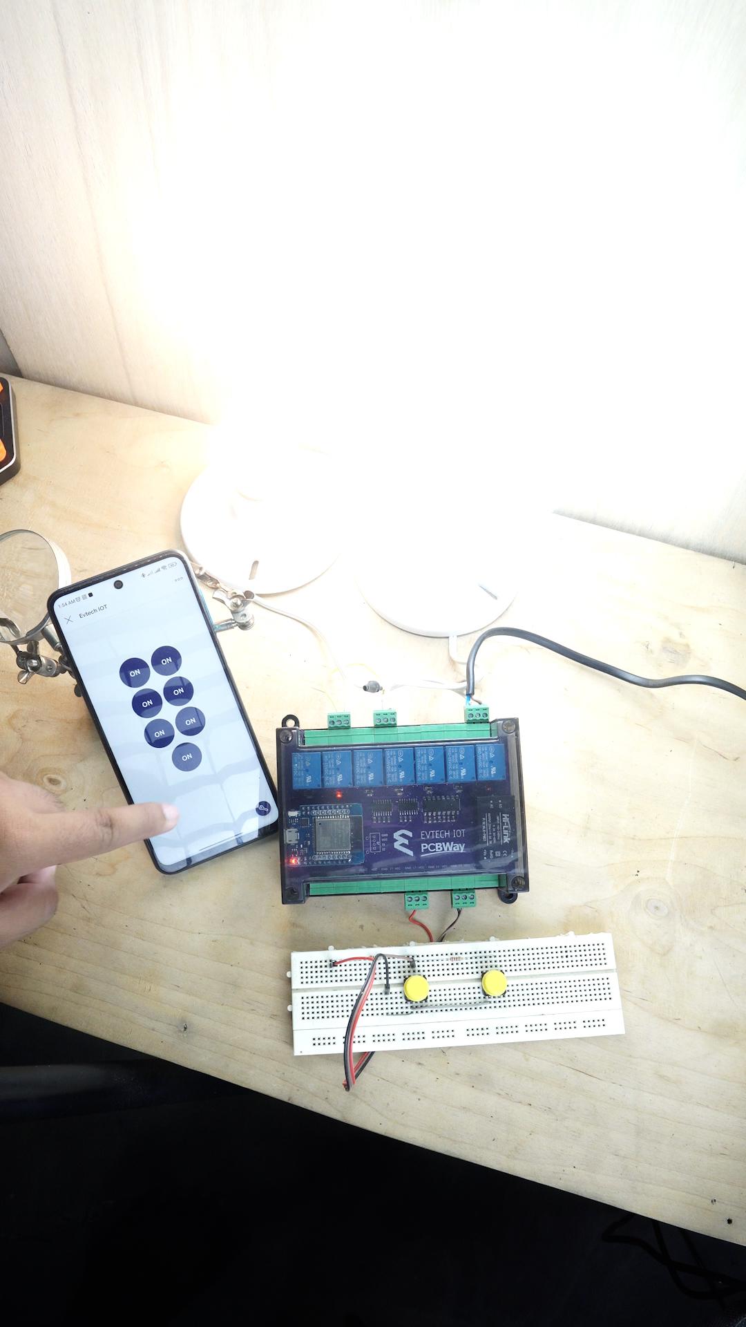
As you can see in the video/ picture, I can control the bulb using my mobile phone, and if there's no internet connection, you can manually control your electronic devices using a switch.
And that's how you make an Evtech IOT - Universal Controller.
And as always, keep learning and have fun! Byiee!