Home Automation Step by Step Using Wemos D1 Mini With PCB Design
by jithinsanal1610 in Circuits > Arduino
3221 Views, 1 Favorites, 0 Comments
Home Automation Step by Step Using Wemos D1 Mini With PCB Design

Home Automation Step by Step using Wemos D1 Mini with PCB Design
A few weeks back we published a tutorial “Home Automation using Raspberry Pi” in rootsaid.com which was well received among hobbyists and college students. Then one of our members came up with an Arduino Home Automation system using NodeMCU.
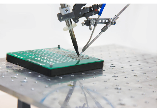
Arduino Home Automation System Here we will be showing you how to build an Arduino Home Automation System that can control electrical devices like lights, fans, garage doors etc using our mobile phone from anywhere around the world. To build this DIY Home Automation System, All you need is an Wemos D1 Mini Board, some relays and an android phone.
Online PCB Manufacturer – JLCPCB
.png)
.png)
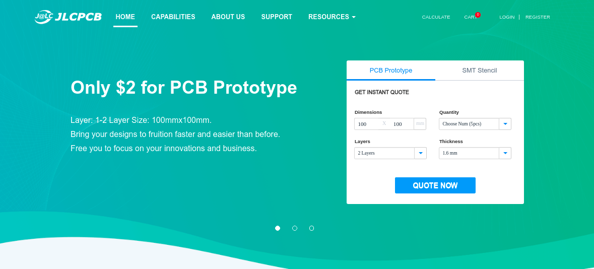
JLCPCB is one of the best Online PCB manufacturing company from where you can order PCBs online without any hassle. The company works 24 hours a day, 7 days a week nonstop. With their high tech machinery and automated work stream, they can manufacture huge quantities of high-class PCBs within hours.
JLCPCB can develop PCBs of various complexity. They develop Simple and cheap PCBs with Single layer board for hobbyists and enthusiasts as well as complex multi layer board for high standard industrial applications. JLC works with large product manufacturers and may be the PCB of devices you are using such as laptop or mobile phones were made at this factory.
Circuit and PCB Layout
.png)

Depending upon the output of arduino board, you can select your relay. Since the Output of Node MCU GPIO pins are 3.3V, you will have to buy a 3.3V Relay.
Voltage Regulator
I also added a 7805, regulator which will helped me to provide an input voltage between 7 volt and 35 volt in the input, so that I can use a 5 volt USB power supply, 9-volt battery or even a 12 volt lithium polymer battery without any issues.
I also added some indicator LEDs that will let me know if something stopped working. You will find the circuit to my EasyEDA below.
PCB Layout
Next, designing the PCB. PCB Layout is actually a significant part of PCB Design, we use PCB Layouts to make PCBs from schematics. I designed a PCB where I could solder all the components together. For that, first save the schematics and from the top tool list, Click on the convert button and Select “Convert to PCB”.
This will open up a window like this. Here, you can place the components inside the boundary and arrange them the way you want. The easy way route all the component is “auto-route” process. For that, Click on the “Route” Tool and Select “Auto Router”.
This will open up an Auto Router Config Page where you can provide details such as clearance, track width, layer information etc. Once you have done that, click on “Run”.
Thats it guys, your layout is now complete. This a dual layer PCB which means the routing is there in both side of the PCB. You can now download the Gerber file and use it to manufacture your PCB from JLCPCB.
PCB Manufacturing
.png)


Getting the PCB Manufactured from JLCPCB
JLCPCB is a PCB manufacturing company with a full production cycle. Which means they start from “A” and finishes with “Z” of PCB manufacturing process.
From raw materials to finished products, everything is done right under the roof. Go to JLC PCBs website and create a free account.
Once you have successfully created an account, Click on “Quote Now” and upload your Gerber File. Gerber File contains information about your PCB such as PCB layout information, Layer information, spacing information, tracks to name a few.
Below the PCB preview, you will see so many options such as PCB Quantity, Texture, Thickness, Color etc. Choose all that are necessary for you. Once everything is done, click on “Save To Cart”. In the next page, you can choose a shipping and payment option and Check Out Securely.
You can either use Paypal or Credit/Debit Card to pay. Thats it guys. Its Done. The PCB will be manufactured and you will received with in the mentioned time period.
Installing the App and Running Home Automation

.png)
Install RootSaid WiFi Command Center from Google PlayStore
RootSaid WiFi Command Center is a simple light weight android application that can be used to control robots and Raspberry pi and Arduino Home Automation over WiFi.
All you have to do is connect your mobile phone to the network, enter the IP address and Port of the server (the NodeMCU of our Home Automation system using Arduino) and control it using the On Off buttons.
Click here to know more about this App. Click Here to Download this app from Playstore. Step 5 Now all you have to do is start the App, enter the IP address of the Pi and port it is listening to (5005).
Load the IP and Port using the link button and navigate to the Home Automation Tab. Thats it, your Home Automation system using Arduino is now ready.
You will find complete Information about the Code from here.
You can now control devices connected to your Node MCU using this simple app and turn it on and off.