Home Assistant Geiger Counter Integration
by danionescu in Circuits > Sensors
3706 Views, 11 Favorites, 0 Comments
Home Assistant Geiger Counter Integration
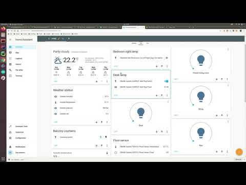
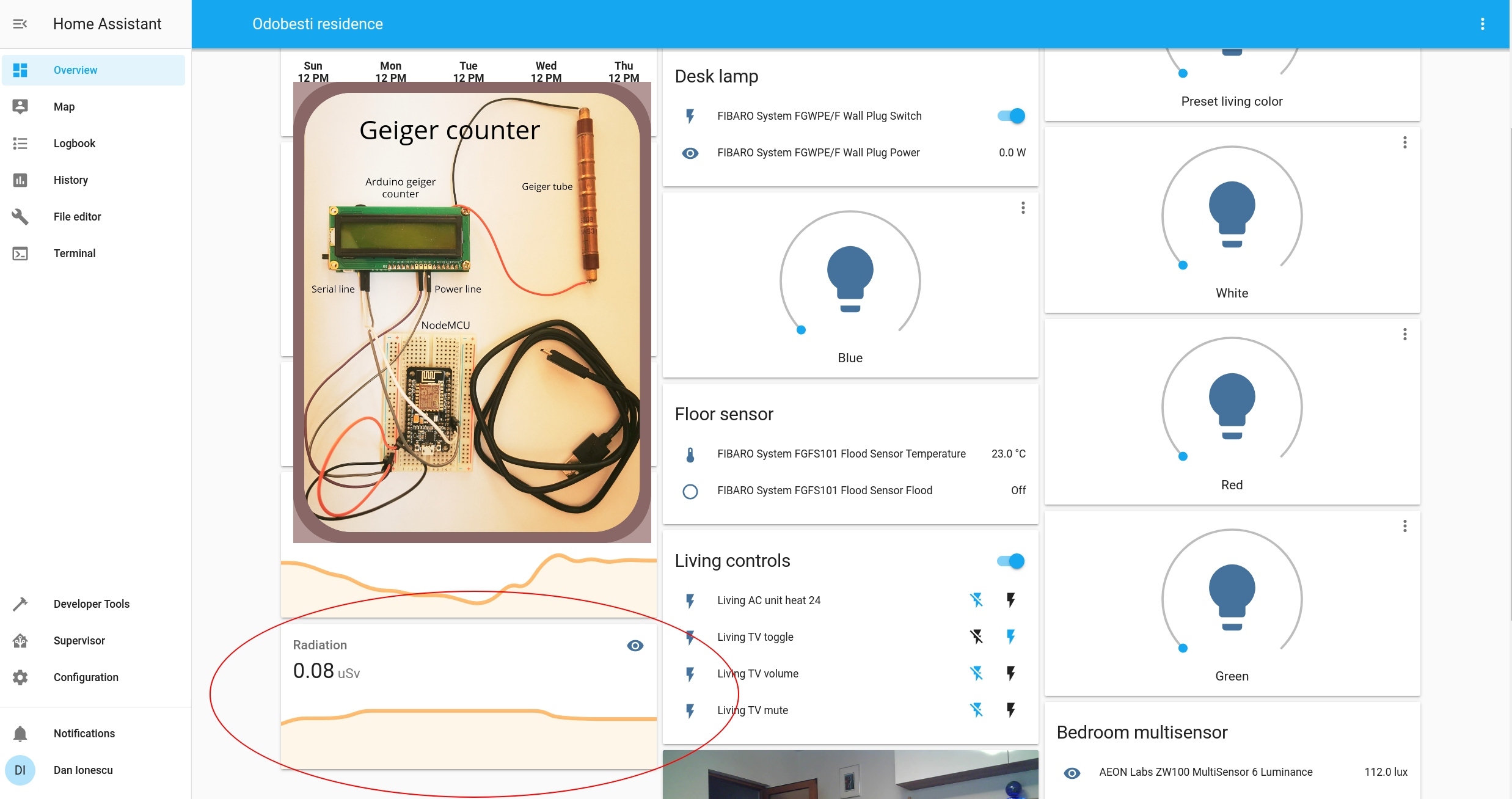
In this tutorial i'm going to show how you how to add custom sensors to HASS (home assistant) more specifically a geiger counter but the process is similar for other sensors too.
We'll be using the NodeMCU board, an arduino based geiger counter and an already installed home assistant.
The integration will be based on a MQTT server (public or private) and i'm going to take you step by step with this.
In case you don't know what is home-assistant please visit their page https://www.home-assistant.io/. It's a well known home automation platform that's very well maintained and highly customizable.
You'll be learning about:
- advanced configuration for Home Assistant
- NodeMCU (development board) and how to program it with the Arduino IDE
- OTA (over the air updates) using the Arduino IDE for the NodeMCU board
- how to connect a serial device to the NodeMCU
- manually installing a MQTT server on linux (optional)
Basic assumptions:
- you have Home Assistant up and running
- you know a bit about electronics
- you have Arduino IDE installed
Parts and Tools
Parts:
1. NodeMCU board
2. breadbord
3. male-male and male-female juper wires
3. usb to micro usb cable
4. arduino geiger counter with serial interface
(search Ebay for "arduino geiger couter")
5. radioactive material (optional a small test sample)
Tools:
1. Arduino IDE
2. Home Assistant installed
Principle of Work
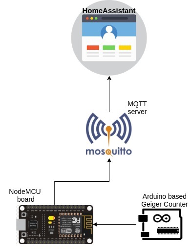
Our goal is to show on HomeAssistat (HASS) the readings from the geiger counter. On one side we have a HASS server up and running somewhere it may be a raspberry pi or other device and on the other side we have the geiger counter.
The geiger counter has a serial port, one solution will be to attach directly the serial port to the RaspberryPi on which the HASS runs.
Some reasons why it may not be a good ideea:
- there is no physical space there
- we have some some other device on the serial port
- we want to attach an environmental sensor that should be placed outside instead of the geiger counter
Ok so we're going to explore another possibility make the connection through WIFI:
The HASS supports reading sensor data and displaying that through an MQTT server, this kind of server is a lite weight connection for small devices one device publish a message on a "topic" the other listens on that topic to receive the message. So HASS will listen, and we need something that will publish the message.
Our sensor knows only to talk over the serial line so we'll use a board that can read a serial line and that can connect over WIFI and talk to the MQTT server. A cheap board that does this is the NodeMCU.
The NodeMCU can be programmed with Arduino IDE. The sketch is pretty simple, it does the following:
- connects to WIFI
- maintains a MQTT connection with the server and retries the connection when failed or disconnected
- listens to serial incoming data as a series of integers
- once an integer arrives it sends it through MQTT to a specific topic
Assemble the Device
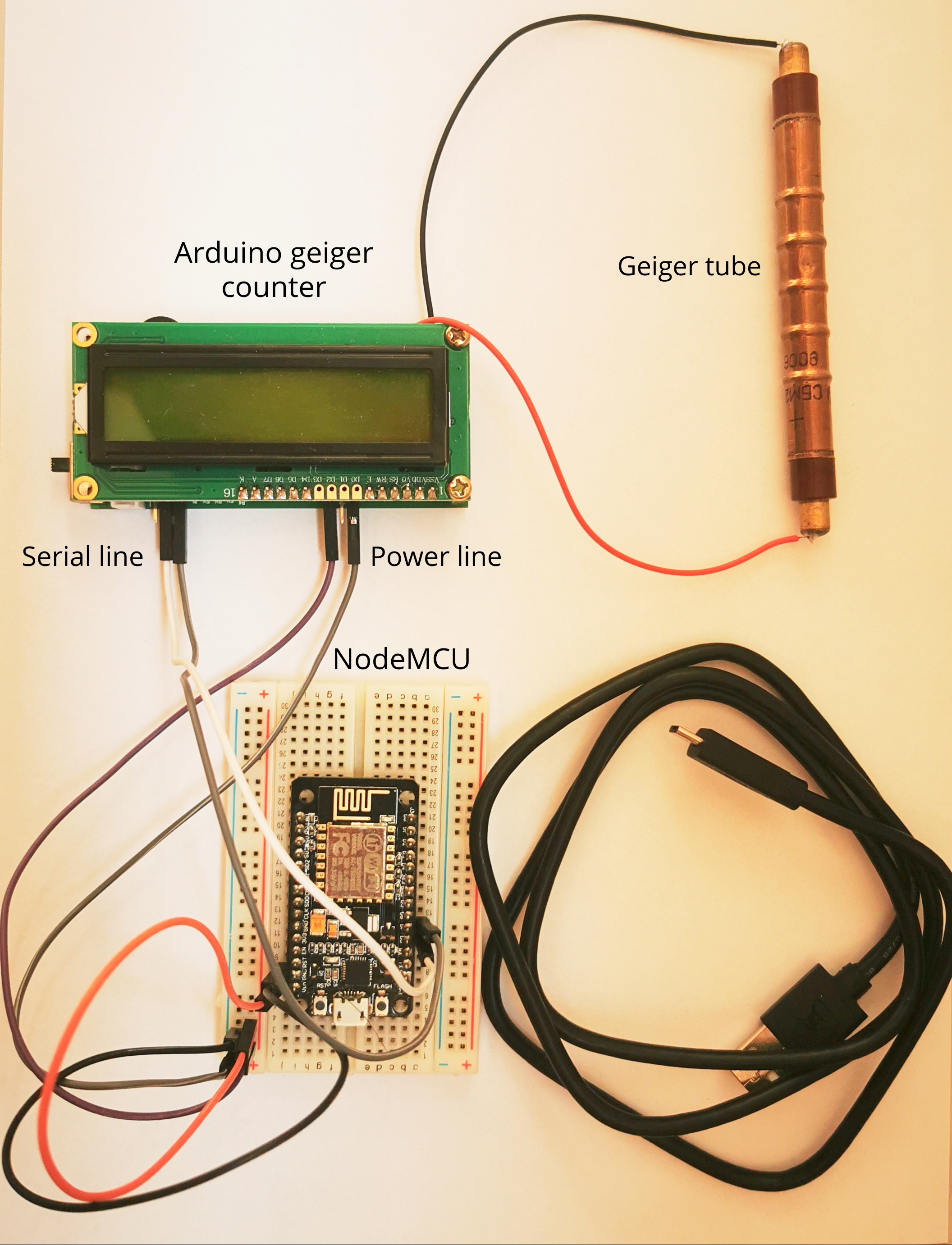
We'll be using breadboards and wires so it's fairly simple, we have a few steps:
- put the NodeMCU on the breadboard
- connect the geiger tube to the geiger counter (watch out for polarity)
- VIN goes to geiger counter +
- GND goest to geiger counter -
- NodeMCU D7 (pin 13) goes to geiger TX
- NodeMCU D8 (pin 15) goes to geiger RX
- power NodeMCU through micro USB from the computer
Upload the Code
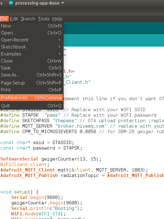
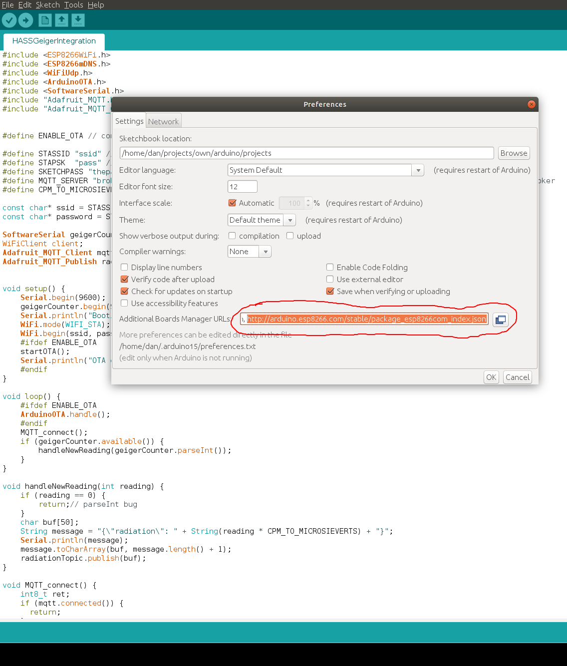
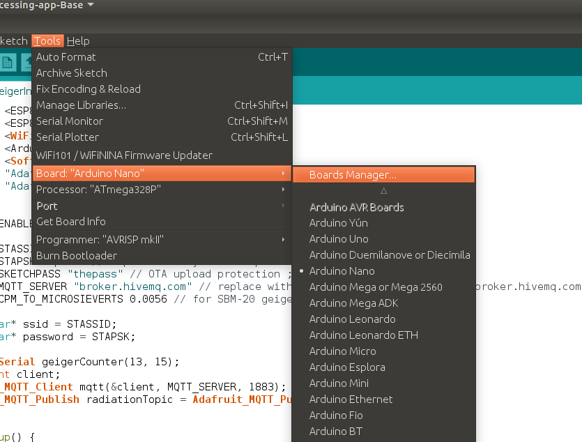
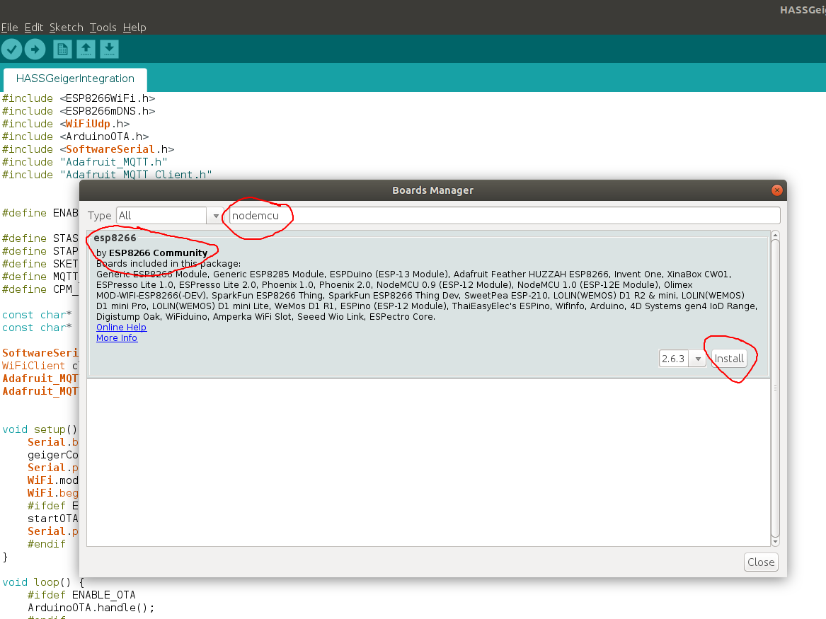
We're going to use Arduino IDE and we'll make sure we have the NodeMCU board installed and the Adafruit_MQTT library installed.
1. Clone the github repository:https://github.com/danionescu0/arduino and copy the sketch from projects/HASSGeigerIntegration to your arduino sketchbook location
2. Open Arduino IDE and install NodeMCU
- go to File -> Preferences , in the Additional Boards Manager URLs add http://arduino.esp8266.com/stable/package_esp8266com_index.json if you already have something there put a coma in front and click ok
- from Tools -> Board -> Board Manager type "nodemcu" and select the entry esp8266 by ESP8266 Community, and press install
3. Install Adafruit_MQTT
- go to Tools -> Manage Libraries -> search "Adafruit_MQTT" and install "Arduino MQTT library"
4. Plug in the USB cable in your computer and configure the board:
- go to Tools -> Board -> select NodeMcu 1.0
- Tools -> Port -> your USB port
- leave the other settings unchanged
4. In the sketch change your WIFI credentials to match your own:
#define STASSID "ssid" // Replace with your WIFI SSID

#define STAPSK  "pass" // Replace with your WIFI password</p>
5. Upload the sketch to your board and after the upload reset the board from the button
6. Open the serial monitor, if all has gone well you should see some output like this:
Booting
IP address: 192.168.1.168
OTA enabled
Connecting to MQTT... MQTT Connected!
{"radiation": 0.03}
..
Configure HomeAssistant
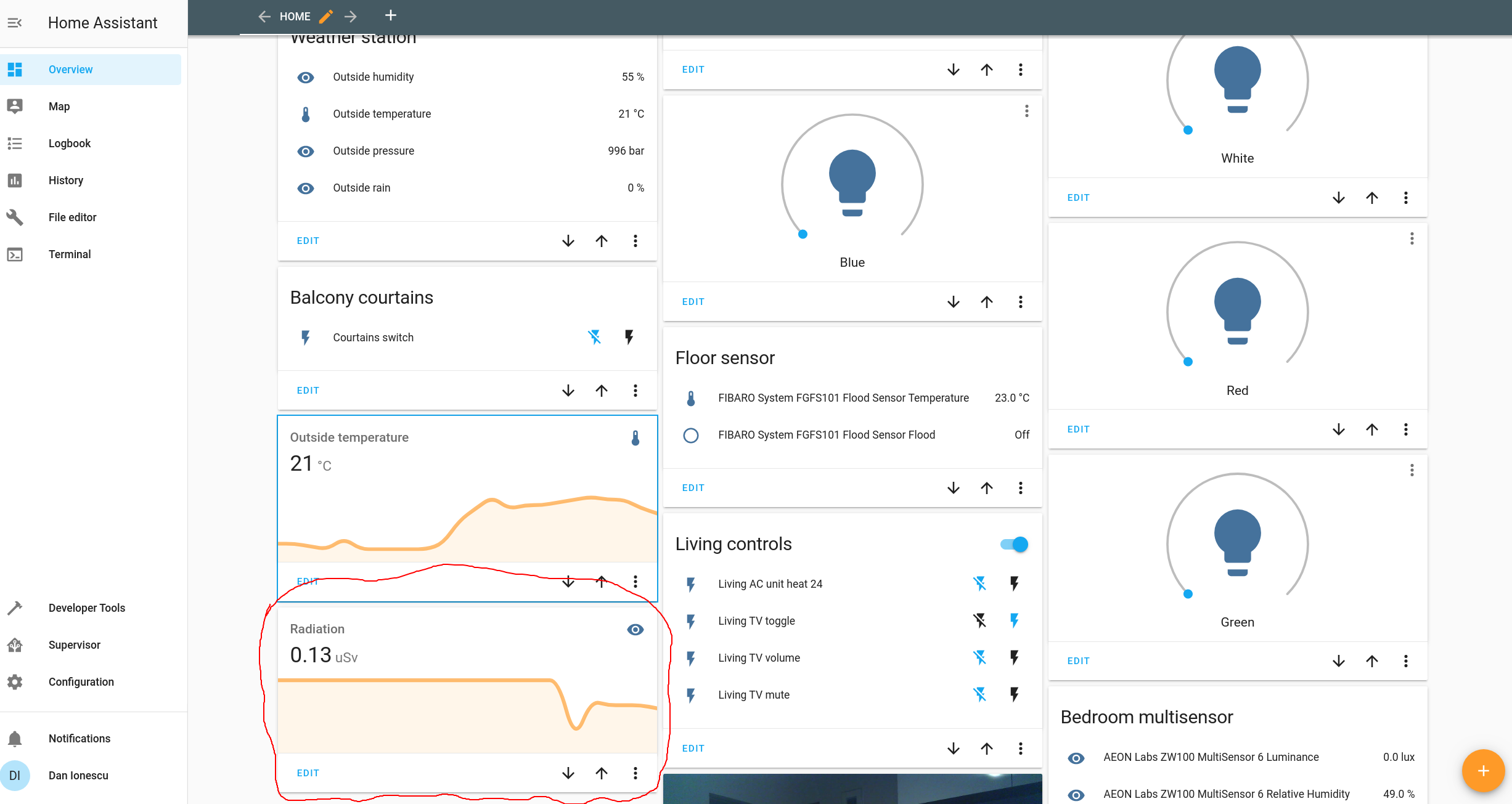
We're going to assume that you have home assistant up and running. On my system i have HASSOS version 3.12 on a RaspberryPi. If your version of home assistant is too old or very new some features may differ. This tutorial works for sure with 3.12 version.
If your don't have Home Assistant installed , check out their official installation guide: https://www.home-assistant.io/getting-started/
Before advancing with the instalation make sure the NodeMCU is plugged and it publishing data.
Ok we'll have a series of steps here too for the configuration:
1. Install "file editor" if you don't have it in the menu, here is the official tutorial: https://www.home-assistant.io/getting-started/configuration/
2. Edit "/config/configuration.yaml" file and add the following and save it
- the mqtt section if you don't have it already
mqtt:
  broker: broker.hivemq.com
  discovery: true
  discovery_prefix: ha
- the sensors section
sensor:
  - platform: mqtt
    name: "Radiation"
    state_topic: "ha/radiation"
    unit_of_measurement: 'uSv'
    unique_id: "radiation"
    value_template: "{{ value_json.radiation }}"
3. From Configuration -> Server controls : press "Check configuration" the check the yaml config file for errors, and then press "restart" and wait until it's restarted
4. From Overview -> Top right corner menu -> Configure UI -> press the + button from the bottom right
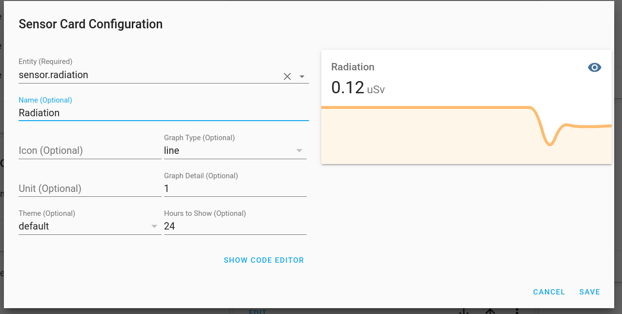
5. Select "sensor" from the list -> in the "entity" field search for "sensor.radiation" , in the name field write "Radiation" and click ok, it should be on the main page now
Configuring Your Own MQTT Server [Optional]
Let's discuss a bit about MQTT
“MQTT is a Client Server publish/subscribe messaging transport protocol. It is light weight, open, simple, and designed so as to be easy to implement. These characteristics make it ideal for use in many situations, including constrained environments such as for communication in Machine to Machine (M2M) and Internet of Things (IoT) contexts where a small code footprint is required and/or network bandwidth is at a premium.”
Citation from the official MQTT 3.1.1 specification.
So basically we can publish a message somewhere on one side and on the other side we can listen for those messages and do something with the data. MQTT support "topics", topics are strings that the broker uses to filter messages for each client so if we publish a message to "/radiation" topic a listener must subscribe to the same topic to get the messages that we're sending.
Here is a great tutorial about MQTT in detail: https://www.hivemq.com/mqtt-essentials/
Using the free hive server there are some disadvantages like:
- anyone listening to your topic will receive your messages
- if it goes down or requires payment later on you won't be able to use it (unless you pay)
- if anyone that publish messages to the same topic you'll receive their messages too, they may publish incompatible messages and break your HASS graphs
Using a private server
If you don't want to use the public free server you have the option of a private server. We're going to install the Mosquitto MQTT on a ubuntu / debian server like a raspberry pi or computer.
Mosquitto is a server that implements MQTT protocol and it's free.
To install it log into your raspnerry pi or other debian based server and run:
sudo apt update
sudo apt install -y mosquitto mosquitto-clients
sudo systemctl enable mosquitto.service
This will update the repository, install mosquiito server and client and enable it a service to run at startup
To get the server ip execute:
hostname -I
and it will output something like:
192.168.1.52 172.17.0.1 172.18.0.1
So my ip is 192.168.1.52, in the commands below replace it with your own ip
You can test the MQTT server by publishing a message and receiving it with the console tool, for this two terminals must be opened one that listens for a message, one that will publish the message.
First in a terminal run this command to listen for a message on "/some-topic"
mosquitto_sub -h 192.168.1.52 -t /some-topic
Open another terminal and publish a message to that topic:
mosquitto_pub -h 192.168.1.52 -t /some-topic -m '{"humidity": 74.0}'In the first terminal you should see '{"humidity": 74.0}' printed out.
Special attention:
- this setup assumes that HASS, Mosquitto and NodeMCU are connected to the same WIFI network and there are no firewall rules and they can communicate freely
- the Mosquitt MQTT server has no username/password, if you do want to setup credentials check this out: http://www.steves-internet-guide.com/mqtt-username-password-example/ Also you would need to configure the credentials in Home Assistant and in the arduino sketch
OTA (Over the Air Updates) for the NodeMCU
Over the air updates means that the development board can be flashed wirelesly without the need of a physical cable.
Arduino IDE supports this functionality for ESP8266 series and some other boards:
- requires initial flash over the USB cable
- creates a virtual port over WIFI and it's visible only from Arduino IDE
- no Serial debug information is available
- supports protection with password
To enable OTA in a ESP8266 sketch first include the library:
#include "ArduinoOTA.h"
Also define this sketch password constant:
#define SKETCHPASS "some_password"
In the setup section add these lines:
while (WiFi.waitForConnectResult() != WL_CONNECTED) {
      Serial.println("Connection Failed! Rebooting...");
      delay(5000);
      ESP.restart();
    }
    ArduinoOTA.setPassword(SKETCHPASS);
    ArduinoOTA.onStart([]() {
        String type;
        if (ArduinoOTA.getCommand() == U_FLASH) {
          type = "sketch";
        } else { // U_FS
          type = "filesystem";
        }
        Serial.println("Start updating " + type);
    });
    ArduinoOTA.onEnd([]() {
        Serial.println("\nEnd");
    });
    ArduinoOTA.onProgress([](unsigned int progress, unsigned int total) {
        Serial.printf("Progress: %u%%\r", (progress / (total / 100)));
    });
    ArduinoOTA.onError([](ota_error_t error) {
        Serial.printf("Error[%u]: ", error);
        if (error == OTA_AUTH_ERROR) {
          Serial.println("Auth Failed");
        } else if (error == OTA_BEGIN_ERROR) {
          Serial.println("Begin Failed");
        } else if (error == OTA_CONNECT_ERROR) {
          Serial.println("Connect Failed");
        } else if (error == OTA_RECEIVE_ERROR) {
          Serial.println("Receive Failed");
        } else if (error == OTA_END_ERROR) {
          Serial.println("End Failed");
        }
    });
    ArduinoOTA.begin();
    Serial.print("IP address: ");
    Serial.println(WiFi.localIP());
And in the loop section add this line:
ArduinoOTA.handle();
After your initial code upload after the board boots up you should see in the Arduino IDE in the Tools->Port section two types of ports:
Serial ports: /dev/ttyUSB0 (for example)
Network ports: esp8266-xxxxx at 192.168.1.xxx
Now you can select the network port and upload the sketch remote, you will be prompted for the sketch password (the one that you have defined in a constant above)
Conclusions, Future Work
This tutorial can be easily modified to send data about other types of sensors:
- if your sensor is directly supported by NodeMCU through a library, just pool data from the sensor and directly push it through MQTT
- if the sensor library doesn't work with NodeMCU but it's only for Arduino then upload your code to the arduino , output the value through the serial line and read it in the NodeMCU and push it (just like we did with the geiger counter)
We can even modify it to send data from multiple sensors like so:
- connect your sensors to the NodeMCU
- poll data from each sensor
- for each of the sensor publish the data to a different topic
- in the HASS define multiple sensors (like we did with the geiger) that will listen to different topics