Home Ambient Lighting Using PICO
by MellBell Electronics in Circuits > Arduino
1992 Views, 8 Favorites, 0 Comments
Home Ambient Lighting Using PICO
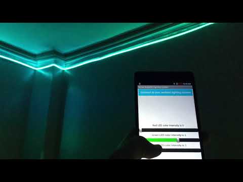
Didn't you ever want to change your room's mood by changing the light's color? Well, today you will learn how to do exactly that. Because, with this project you will create a Bluetooth controlled RGB ambient lighting system that you can place anywhere in your house, and have it colored however you want.
This project will use PICO, an LED RGB strip, some transistors and electrical components, and an app that you will learn how to create using the MIT app inventor.
Components
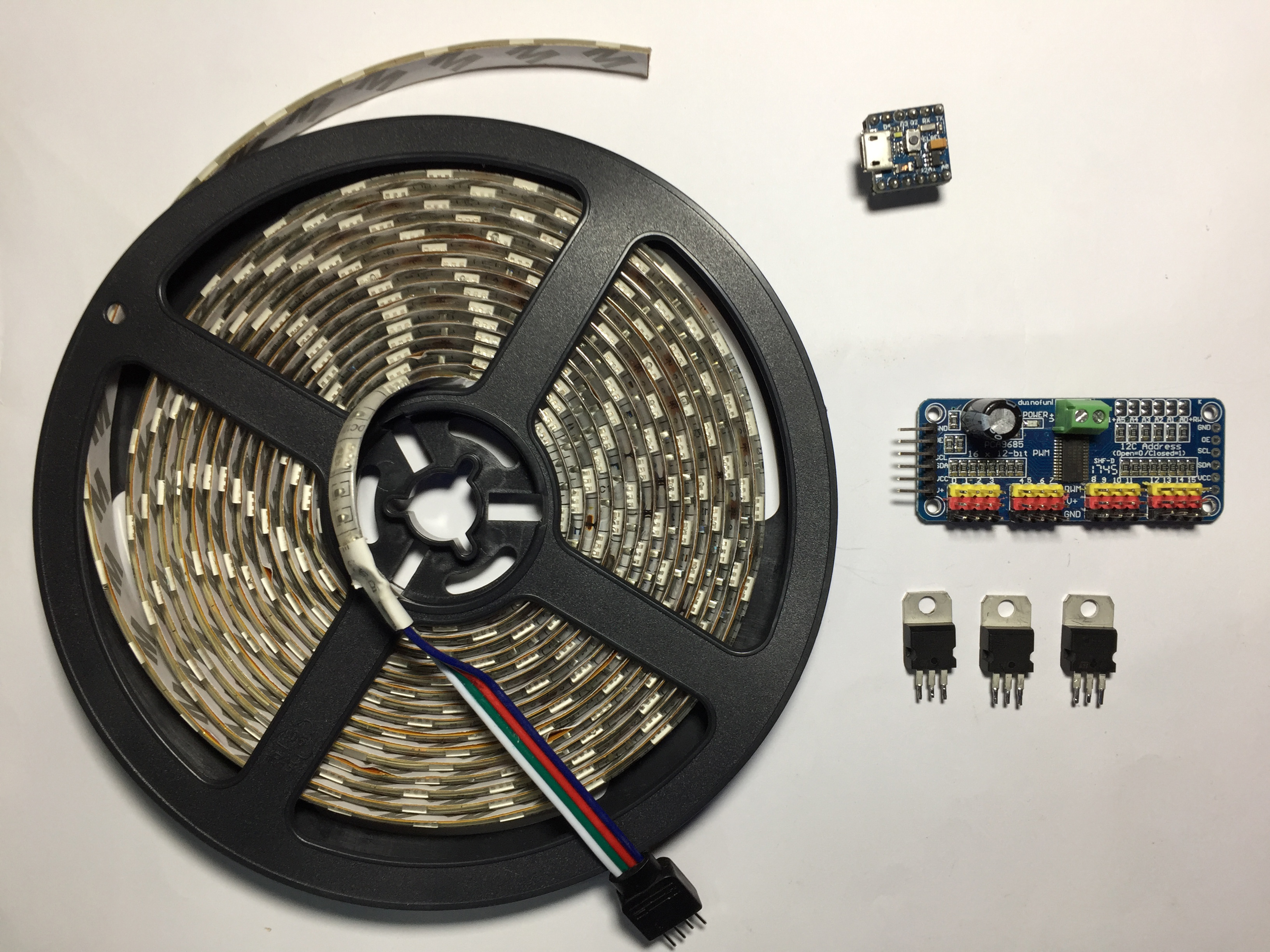
These are the components needed to create this project, and they are:
- PICO, available on mellbell.cc ($17.0)
- A 4 meters RGB LED strip(5050 SMD- 60 LED - 1 M)
- 3 TIP122 Darlington transistors, a bundle of 10 available on ebay ($1.22)
- 1 PCA9685 16-channel 12-bit PWM driver, available on ebay ($2.07)
- 1 HC-05 Bluetooth module, available on ebay ($3.51)
- A 12 volt 5 Amp power supply
- 3 1 k ohm resistors, a bundle of 100 on ebay ($0.99)
- 1 Breadboard, available on ebay ($2.32)
Powering the RGB LED Strip
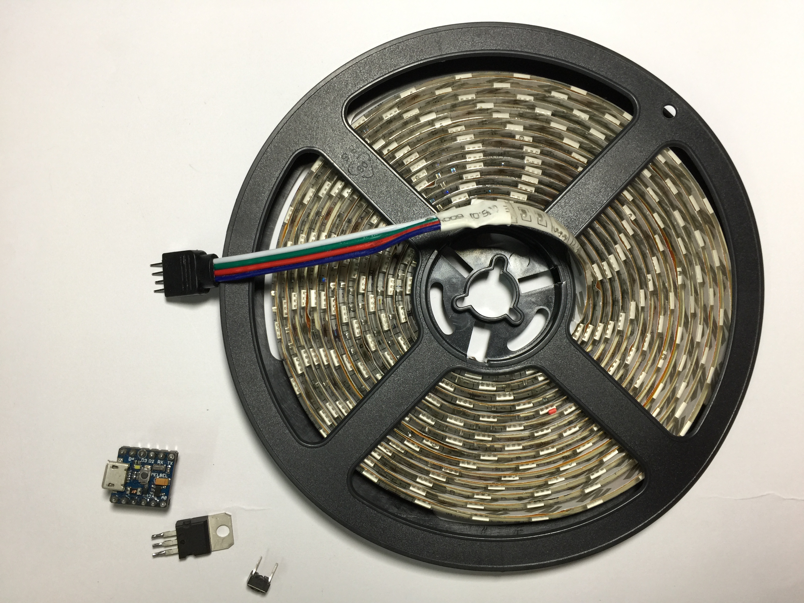
We of course want to connect the LED strip to our PICO to light it up and control it.
But, before anything, we need to do some math to know how much current our LED strip is going to draw from the power source. In the strip that we are working with, each LED in a single RGB cell draws 20mA, for the total of 60mA for the whole RGB cell. Our strip has 20 RGB cells per meter, and we have a 4 meters long one. Which means that our total current draw at maximum intensity is:
4(meters) * 20(cell/meter) * 60(mA) = 4800mA
This draw will vary depending on the intensity that you are working with, but we did the math with the highest possible numbers, so that we can work freely and safely with the RGB strip. Now, we need a power source that can provide us with 4.8A.
The best power source that we can use is a power supply/converter that converts AC power to DC, we also need it to offer 12 volts and at least 4.8 amps. And we have exactly that, as the power supply that we are using offers 12 volts and 5 amps, which is exactly what we need.
Connecting the RGB Strip to the Power Supply
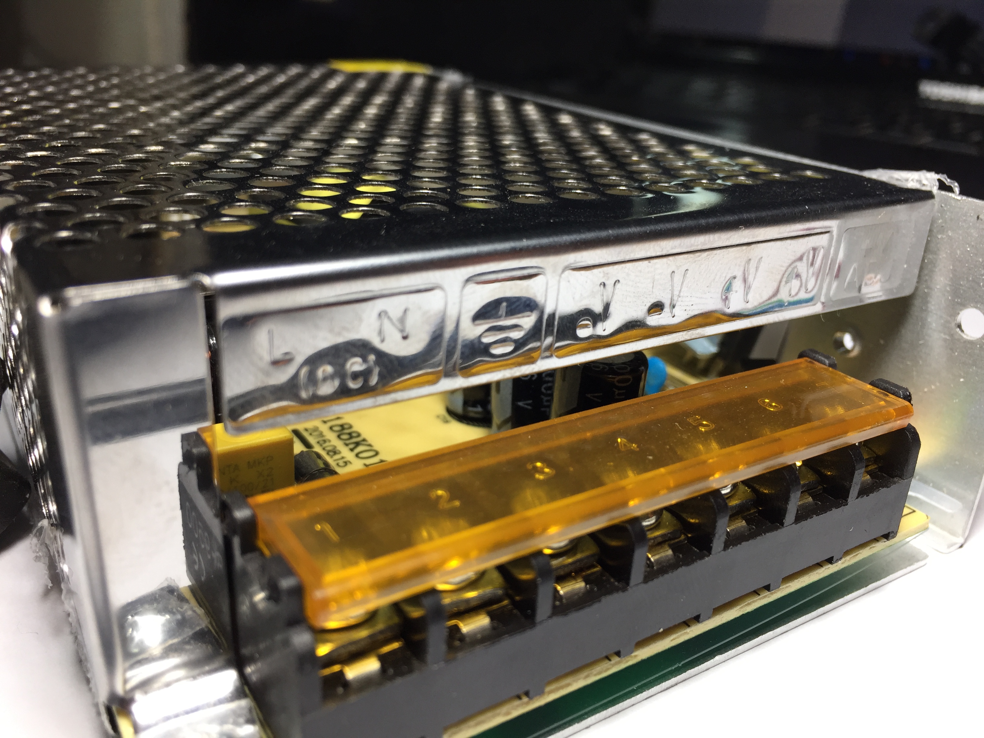
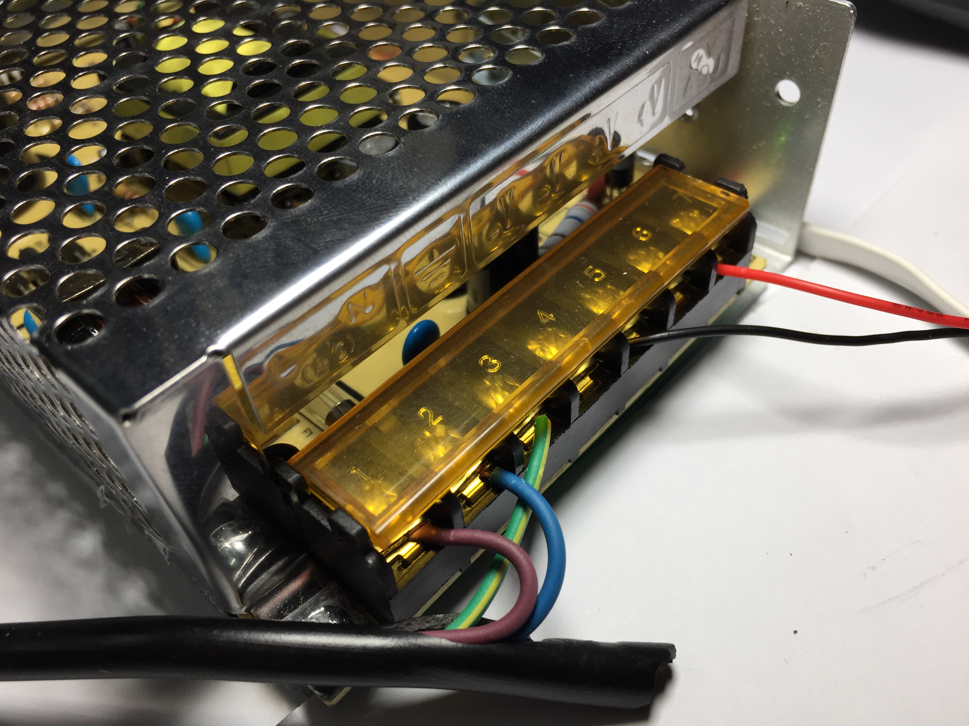
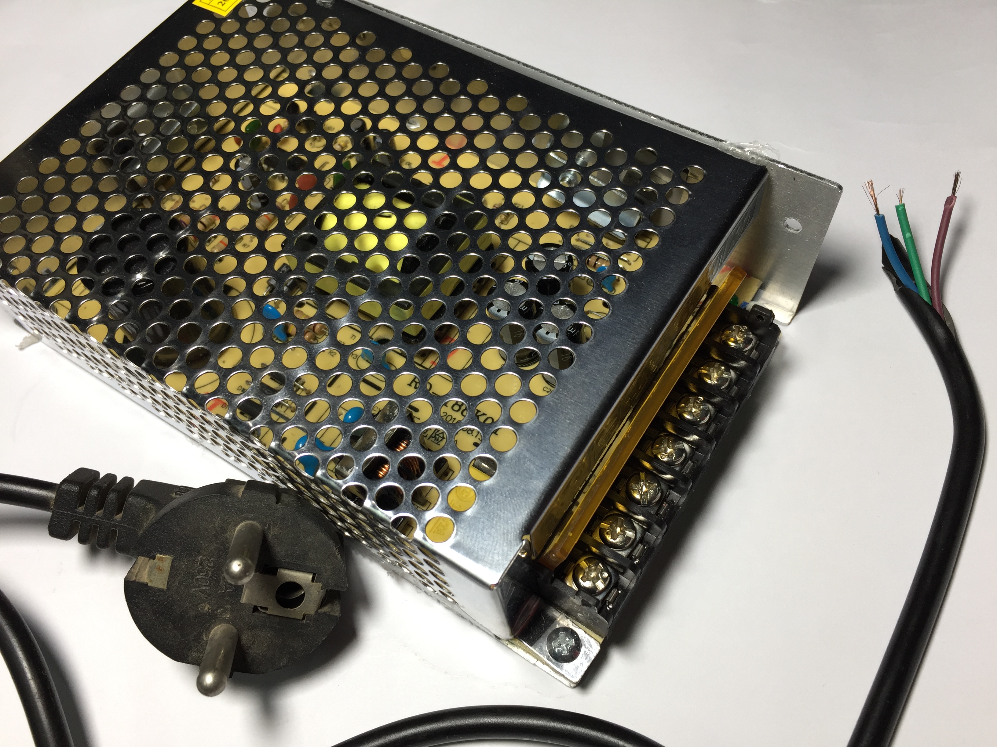
A power supply is an electrical device that converts one type of electrical power to another. In our case, we are going to use it to convert the 220v AC power, to 12v DC power.
The first three terminals are the inputs from the AC power source:
- L → live
- N → neutral
- GND → earth
The last four terminals are the outputs to the electrical device you need. It is divided into two "sections", one for the positive output, and the other for the negative. In our case we are going to use the following:
- V- → negative
- V+ → positive
And we connect them as follows:
- Brown wire (AC power source)→ L (live)
- Blue wire (AC power source) → N (neutral)
- Green wire (AC power source) → GND (earth)
And the red and black wires are the output 12v DC power:
- Red wire → output positive (V+)
- Black wire → output negative (V-)
Now lets connect all of our components to PICO!
Connecting Everything to PICO
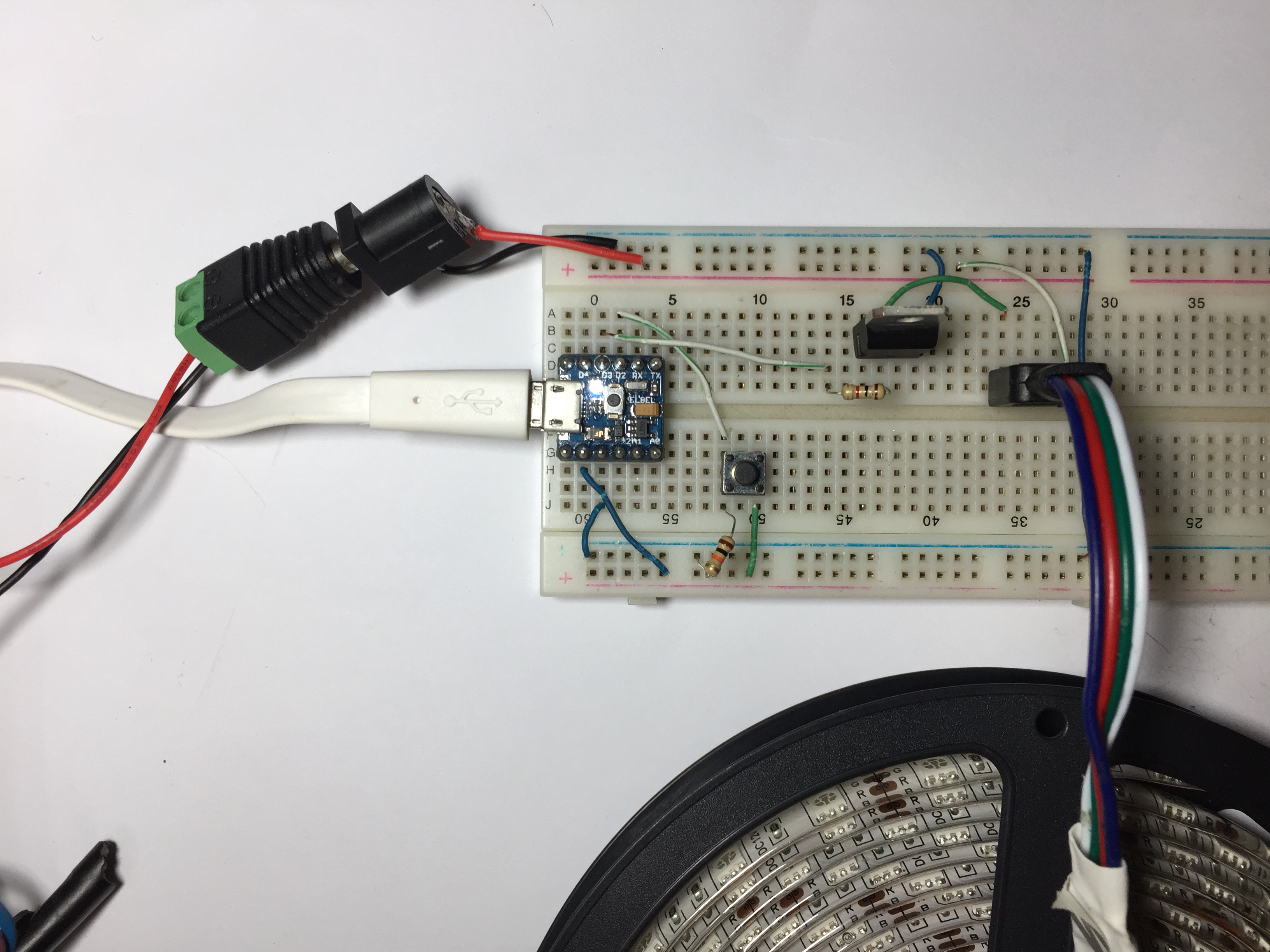
As we said earlier, the LED strip needs 12v and 4.8A to fully operate. And we know that the maximum current that any PICO pin can provide is only 40mA, which isn't enough. But, there is a solution for this, and it is the TIP122 Darlington Transistor, which can be used to drive high power loads by using small amounts of current and voltage.
The wiring is pretty simple, we will connect the base of the transistor to PICO’s D3 pin to control the led strip brightness using the PWM technique, the emitter to GND, and the collector with the load.
- Base (TIP122) → D3 (PICO)
- Collector (TIP122) → B (LED strip)
- Emitter (TIP122) → GND
Also we are using a push button to turn on or off the LED strip.
A push button is a component that connects two points in a circuit only when it’s pressed, it has no polarity so we can connect it with no concern about which leg goes to which side. In our case, we'll be connecting one of the push button legs to the GND through a pull-down resistor, and connecting the other leg to the VCC(5 volt). After that, we will connect PICO's D2 with the push button's leg that is connected to GND.
So, when the button is pressed the PICO’s D2 pin will read HIGH(5 volt), and when it’s not pressed PICO’s D2 pin will read low(0 volt).
Then we'll connect the LED to the power supply and the TIP122 transistor.
- +12 (LED strip) → positive 12 volt output (power supply)
- B (LED strip) → collector (TIP122).
Don’t forget to connect the power supply output negative wire(black wire) with the PICO’s GND pin.
Downloads
Connecting the RGB Strip With PCA9685
Now that we can control a single color from the RGB strip, lets make it that we can control all of the RGB strip's colors. To do so we have to use PWM signals to control the strip.
As we know, PICO only has a single PWM output, and the fix for that is the PCA9685 PWM pins expanding module. This module expands your board's PWM pins, , and we will use it alongside some TIP122 Darlington transistors to fix this issue.
The circuit's wiring is very simple, and it goes as follows:
- VCC (PCA9685) → VCC (PICO)
- GND (PCA9685) → GND (PICO)
We have to power the PCA9685 module using PICO, so that it can function properly.
- SCL (PCA9685) → D3 (PICO)
- SDA (PCA9685) → D2 (PICO)
Here we connect the PCA9685's I2C protocol pins SCL, and SDA to PICO's D3, and D2, so that they can communicate with each other.
We then connect the RGB strip's +12 with the positive lead of the power supply, and the G, R, B leads of the RGB strip to the TIP122 controller pins to feed the LED strip with the needed power from the external power supply.
The code is very simple, we just need to turn on and off all the three colors of the LED strip each one individually at it’s own, so we are making a two for loops for each color, the first for loop is for increasing the light intensity and the second one is for decreasing the light intensity,
Downloads
Creating the Mobile App
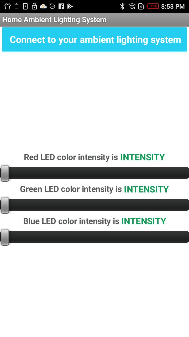
We now want to build the mobile app that will let us control the intensity of each color individually. And we are going to use the MIT app inventor tool to do so.
First, you have to go to the MIT app inventor official website and create an account with your email.
In the design that we'll be using we have:
- One list picker, "Connect to your ambient lighting system". Pressing this list/button will open a menu with the Bluetooth paired devices where we will choose our Bluetooth device from.
- Three sliders for controlling the individual colors
- A label above each slider that will be updated depending on the slider's position
- Adding the Bluetooth client component, to give the app the permission to use the Bluetooth of the device
The code will be divided into two parts:
- Bluetooth Connectivity
The first two lines of the code handle the Bluetooth communication process, as they give you the ability to add devices and choosing what to pair with.
- Sending Data
The rest of the code is for sending data. As it controls what sliding the sliders mean for PICO, it also updates the readings of the slider's labels.
You can download the app if you don't want to create it yourself. You can also download it then import it along with the design in the MIT app inventor tool and customize it to your liking.
Interfacing the HC-05 Bluetooth Module
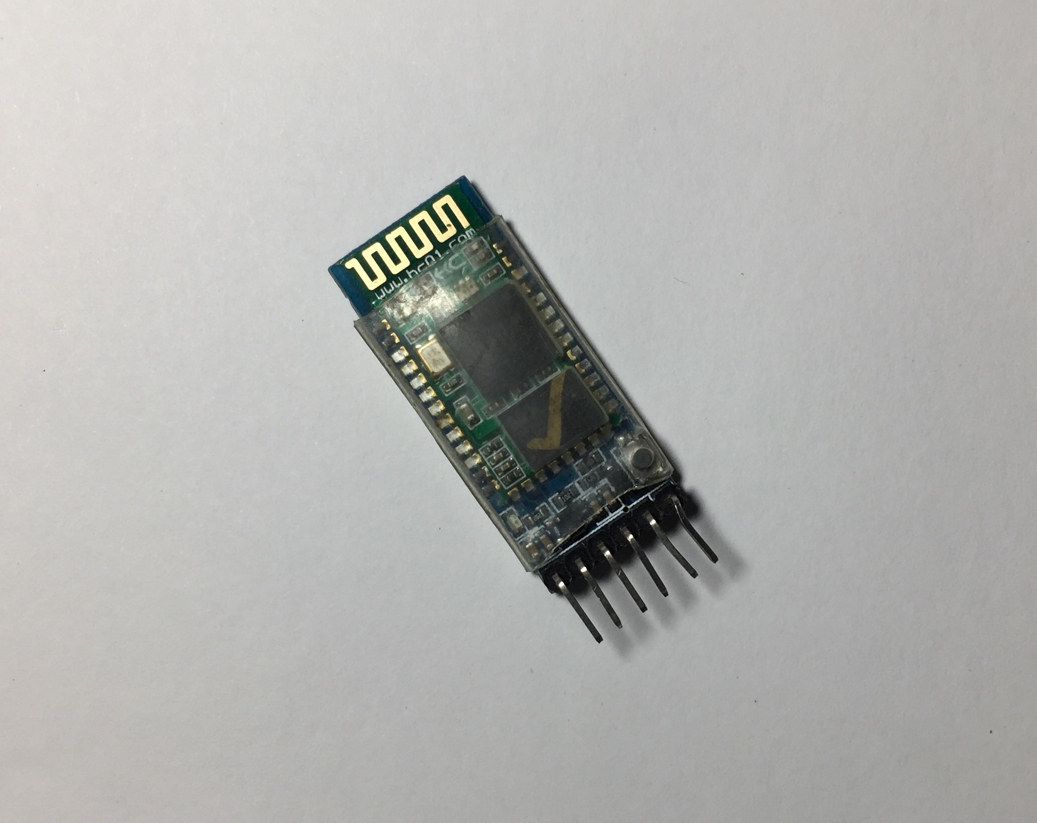
Now we just need to add Bluetooth connectivity to our PICO, and we will do so by using the HC-05 Bluetooth module.
This module is very simple and easy to use, as it is a SPP (Serial Port Protocol) module, which means that it only needs two wires (Tx, and Rx) to communicate with PICO. This module also works as slave and master, and has the connectivity range of about 15 meters.
The HC-05 Bluetooth module pin outs:
- EN or KEY → If brought to HIGH before the power is applied, it forces the AT commands setup mode.
- VCC → +5 power
- GND → Negative
- Tx → Transmit the data from the HC-05 module to PICO's serial receiver
- Rx → Receives serial data from PICO's serial transmitter
- State → Tells if the device is connected or not
And here is how you connect it to PICO:
- VCC (HC-05) → VCC (PICO)
- GND (HC-05) → GND (PICO)
- Tx (HC-05) → Rx (PICO)
- Rx (HC-05) → Tx (PICO)
Now that we have the Bluetooth module connected to PICO, lets edit our program so that we can control the LED strip from our phone.
Coding the Bluetooth Module
According to our plan, we wanted the ability to control the LED strips from our phone. And we didn't just want to control the LED strip, but we wanted to control each color individually.
And we'll do that be having each slider from our app send a different set of values to PICO:
- The red color slider sends a value between 1000 and 1010
- The green color slider sends a value between 2000-2010
- The blue color slider sends a value between 3000-3010
We will use an "if" condition to check the data and know what range of values is changing. For example: if the value is changing between 1000 and 1010, PICO will know that we are changing the red color, and it will remap it accordingly. It will also do this for all values that you created, letting you control each color separately with its slider.
Downloads
Your Project Is Lit!
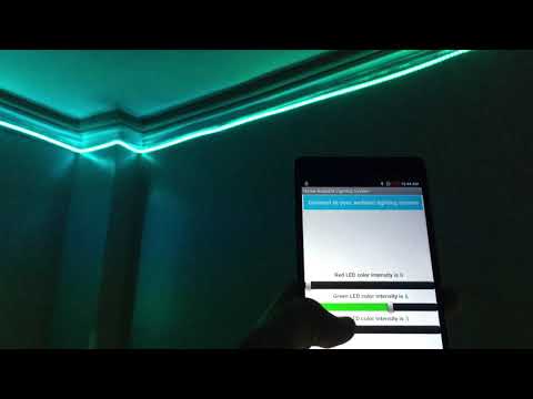
We learned how to calculate the needed power for an RGB LED strip, how to use transistors to manipulate current values, and how to decide on the power supply needed to do all of that. We also learned how to create a mobile app using the MIT app inventor tool, and how to connect it via Bluetooth to PICO.
And with all of your new skills you were able to create an LED strip that you can place anywhere in your house, and have it light with any color you want, how cool is that?
Don't forget to ask any questions if you have any, and see you soon in the next project :D