Hitech Name Badge
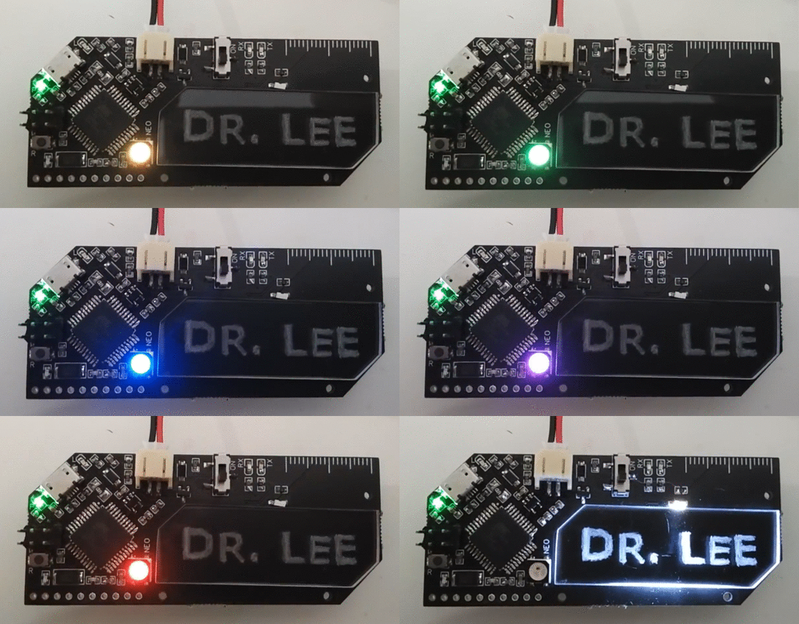
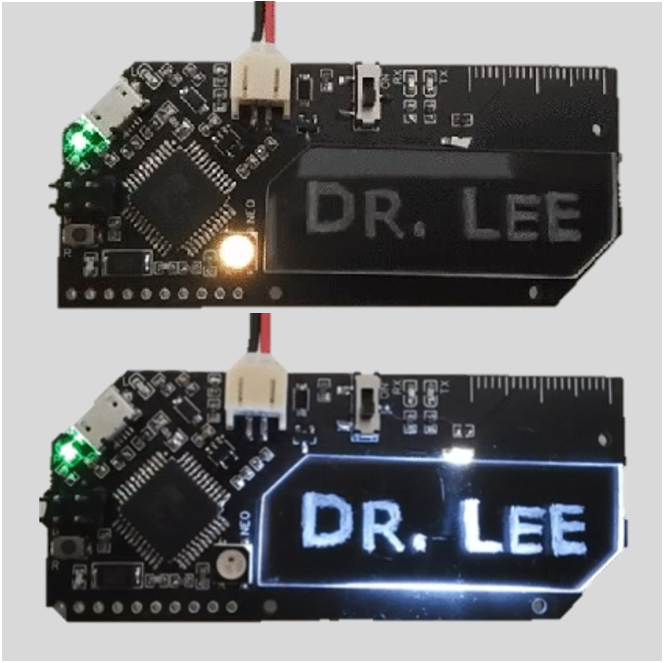
This is a fancy, customized name badge that was made as a congratulatory gift for friends who finished their PhD.
Supplies
- An interactive BOM for the electronic components is located here. A csv file can be downloaded from here
- 2mm acrylic sheet to engrave the name on
- Access to a laser cutter to cut the name tag. Alternatively, a fine saw can be used. Try not to crack the acrylic.
- Engraving tool
- Sandpaper
- Soldering iron, solder and flux
- A couple of CR2032 batteries or a LiPo battery
- Access to a 3D printer to print a battery holder
- Magnetic badge holders
- A spare Arduino UNO or some other board to use as a programmer
Front
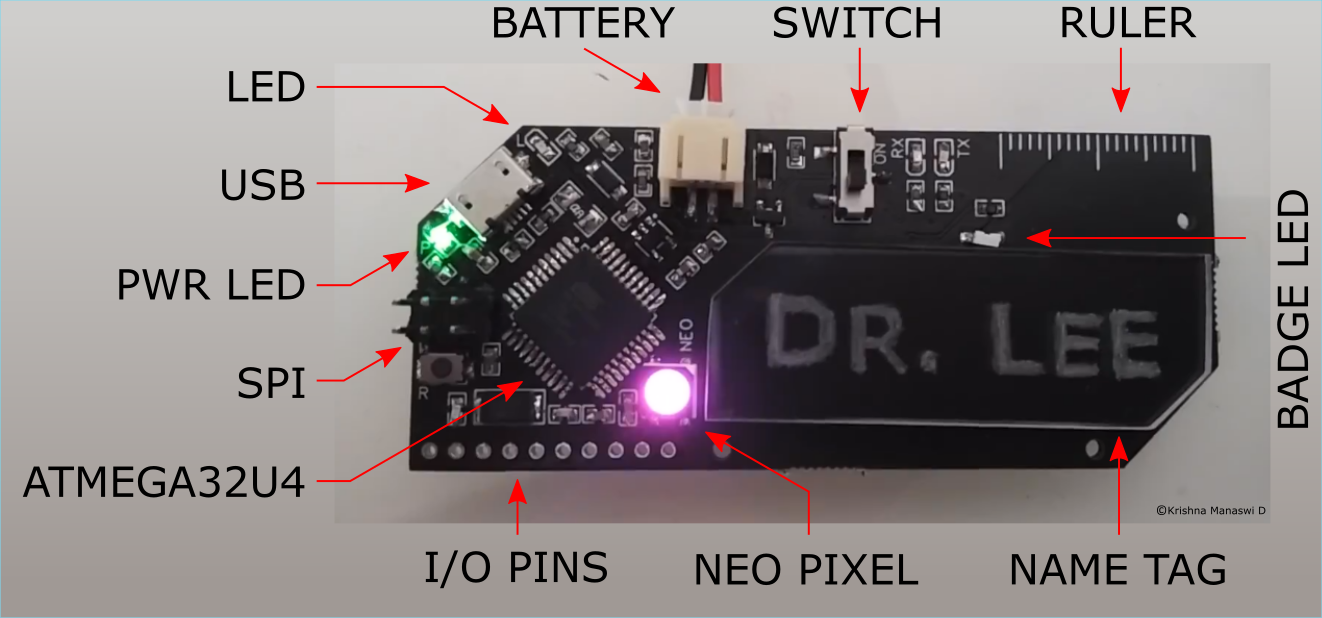
An engraved name tag with a built in micro-controller and a ruler to measure their tiny egos with.
The name tag is edge lit and shines using internally reflected light.
Back
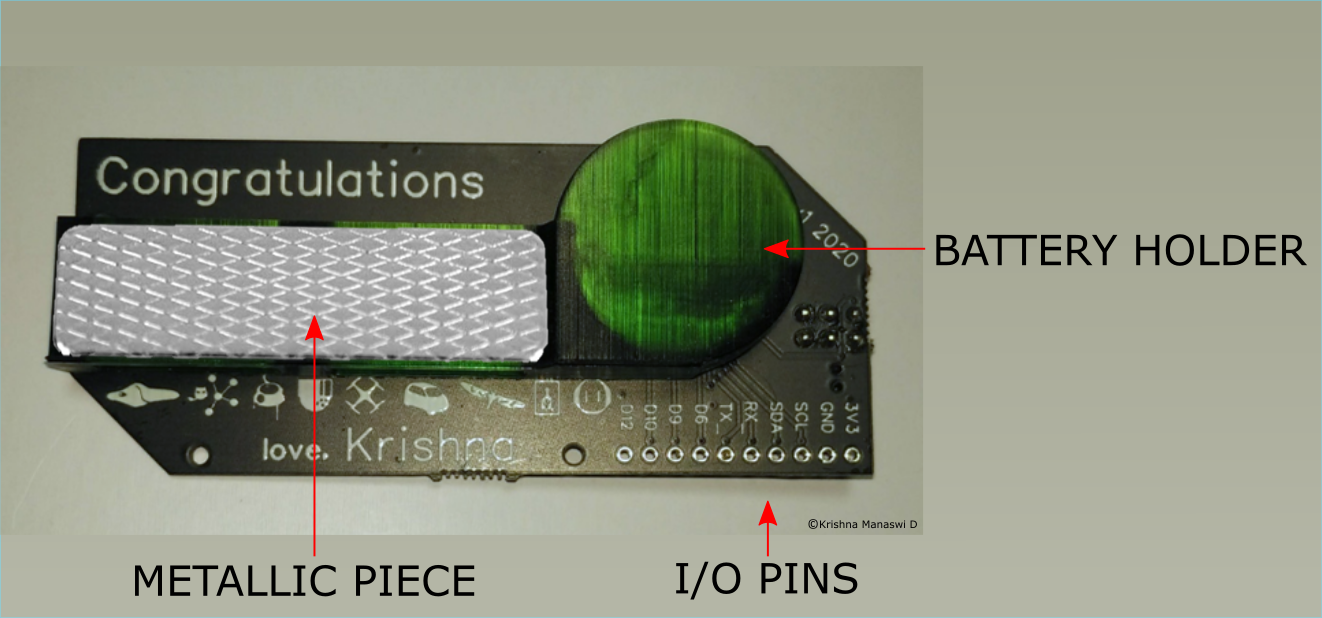
A pictorial representation of our theses and a battery holder with a magnetic piece.
Schematic
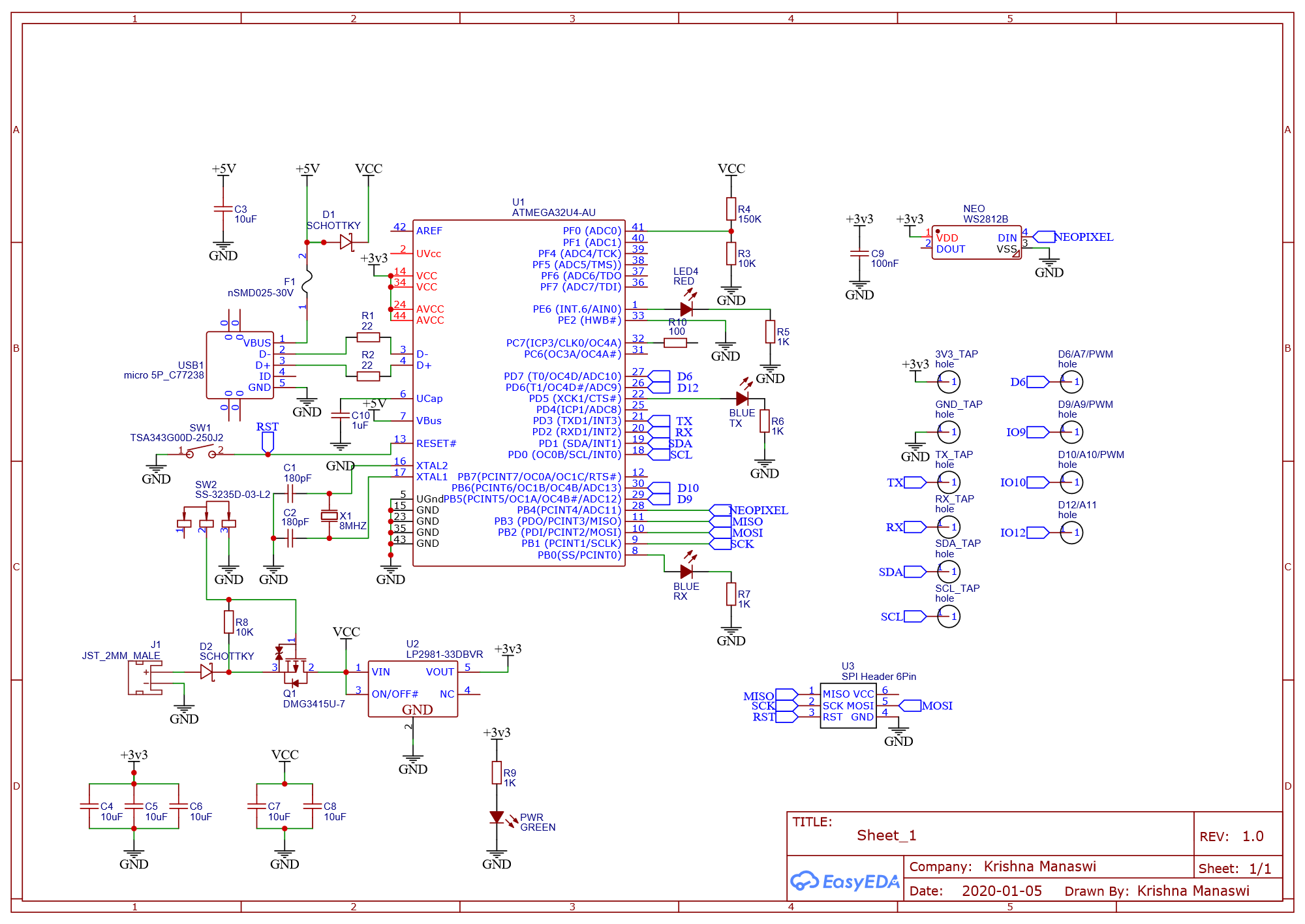
The circuit is a modification of the Adafruit Flora board. The schematic was first drawn in easyeda. A pdf version of the schematic can be accessed here.
Be sure to check out the mistakes at the end of the instructable before copying this design.
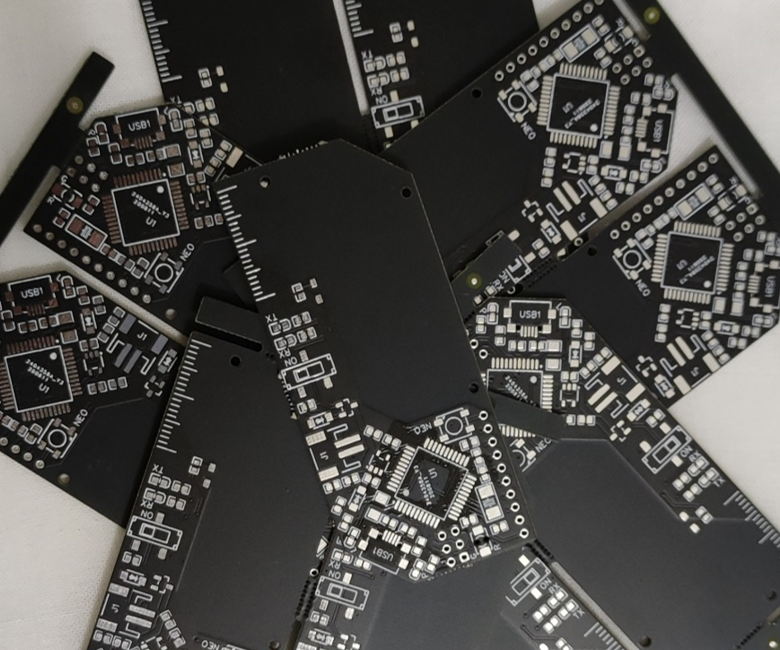
Getting the PCBs Manufactured
Solder the Components
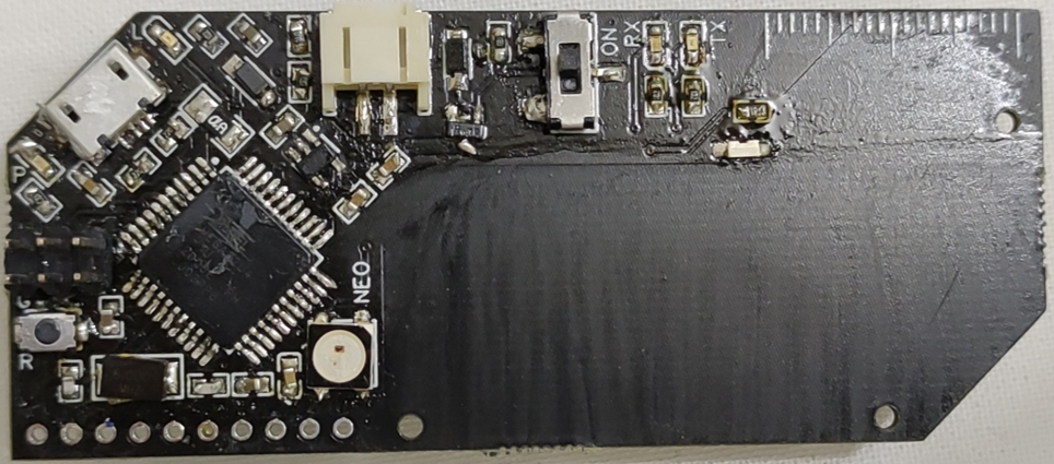
After the boards arrive, solder the components. They were purchased from LCSC, and are common enough to be available from most other suppliers. All the components except the battery are on the front. They can be soldered by hand with a cheap soldering iron. A pointed tip works best. If you have some steel wool handy, it helps with keeping the tip clean. Use plenty of flux. I recommend a flux pen like this one.
- First solder the microcontroller.
- Then do the USB port.
- The other ICs can be done next.
- Do the WS2812 LED
- Finally do the passives and, switches and JST connector.
Doing the hardest ones first makes soldering a more pleasant experience. Use the interactive BOM to keep track of what goes where.
3D Print the Battery Holder
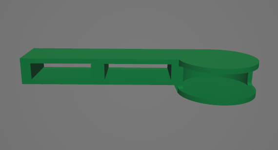
The battery holder is designed to hold two CR2032 batteries (3V each) in the circular portion or a small 3.7V LiPo battery in the rectangular section.
It was printed using an Anycubic Photon S. An FDM printer will also work fine. The stl file can be downloaded from here. Once done, glue it on the back.
The badge has an onboard regulator that supplies 3.3V to the chips. Connect the batteries using the JST header. If you are using CR2032 batteries, solder a couple of battery contact plates from an old battery holder to a JST plug. This way you will have a guaranteed contact and an easy way to plug the battery in. Be sure to check the polarity.
Affix the Metallic Plate

I used a generic magnetic badge attachment to use the circut as a badge. They are sold for cheap on ebay or amazon. When you buy them, they come with two parts. One is a metallic bar. The other is a bar with magnets. Glue the plain metallic bar without the magnets onto the 3D printed battery holder.
Engrave the Name
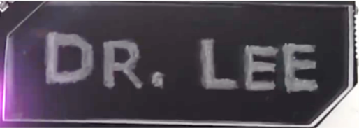
The name plates were cut out of acrylic using a laser cutter. A dxf file is provided here. One can also cut them by hand using a fine saw.
The engraving was done by hand using a rotary tool. Alternatively, you can do the engraving on the laser cutter itself for a cleaner finish. Sand all the sides to maximise internal reflection and make the engraved portion shine brighter. Then glue it in place on the front using clear double sided tape. I used 3M VHB 3905.
Programming
The board is very similar in design to the Adafruit Flora.
There are a few differences like extra I/O pins and LEDs but you can treat it in a similar manner. To set it up like an Adafruit Flora, you need to burn the correct bootloader. The advantage is that the Arduino IDE recognises the board as a Flora and you can program it through the USB port. The disadvantage is that the additional pin functionality is lost.
Alternatively, you can treat the board like a programmable chip and write custom code on it through the SPI header.
Follow the steps below to set it up in whichever way you want. Both methods require the use of a programmer. An Arduino UNO that is set up as an ISP will do fine.
Convert an Arduino UNO to a programmer
- Connect a working Arduino UNO to your computer.
- Using the Arduino IDE, burn the ArduinoISP sketch from the provided examples. Your Arduino UNO is now a programmer.
For more details, you can refer here
Connecting the Arduino UNO to the badge
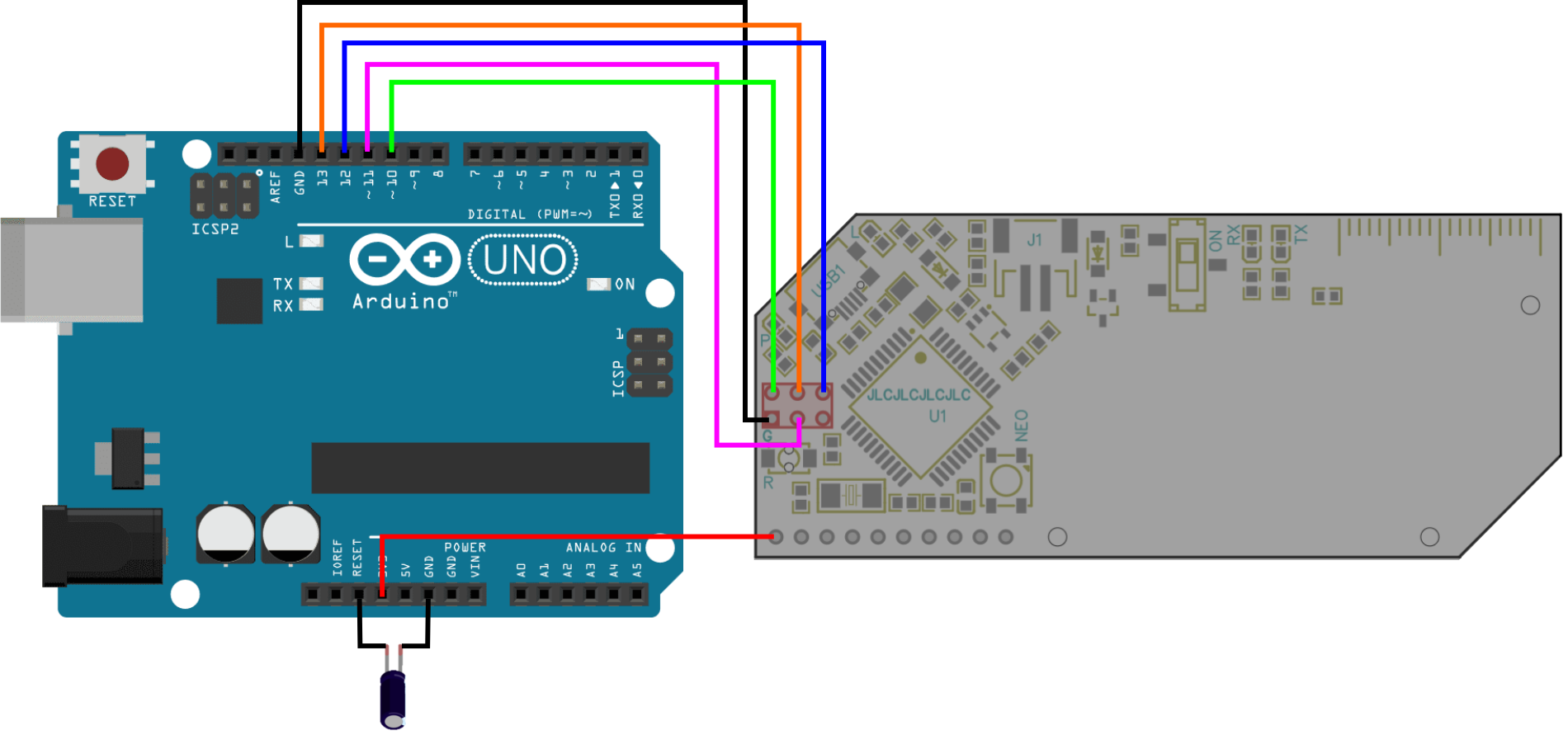
You will need to connect the SPI headers as shown below.
UNO -- Badge
Pin 10 -- RESET
Pin 11 -- MOSI
Pin 12 -- MISO
Pin 13 -- SCK
GND -- GND
3V3 -- 3V3
If you are looking at the front of the badge, the SPI header is to the left of the ATMEGA32U4 chip. The pins are as follows. The square pad is the GND pin in my design.
RESET SCK MISO
GND MOSI VCC
Note: You will also need to use a 10µF electrolytic capacitor between RESET and GND on the UNO when using it as a programmer. Connect this only after burning the ArduinoISP sketch.
Additional note: The VCC pin on the badge pcb is not connected to anything else. To power the board during programming, connect the 3V3 pin on the UNO to the 3v3 pin on the badge (first hole on the bottom left). Be careful that you are using the 3V3 pin from the UNO and not the 5V pin. The badge only runs at 3.3V. You should also be careful that the connection is stable for the entire duration of the programming and does not dislodge as the badge is being programmed. Else, you risk bricking the board. You can also try providing power with a battery.
Option 1: Burning the Adafruit Flora bootloader to the badge
- First, make sure you have the relevant bootloader. Install the Adafruit boards to the Arduino IDE by following the instructions here.
- Connect the UNO to the badge as described in the section above. Double check the 3V3 cable.
- Under Tools -> Board, choose Adafruit Flora.
- Under Tools -> Port, choose the port that the UNO is connected to.
- Under Tools -> Programmer, choose Arduinoo as ISP
- When you are ready, click on Burn Bootloader in the Tools menu.
Your board should now be detected as an Adafruit Flora. You might have to install the relevant drivers on Windows. See here. You dont need the UNO anymore. Use the badge as if you use a regular Arduino. A ton of Flora related tutorials can be found here.
Option 2: No bootloader. Use an UNO to upload a sketch to the badge each time
- In the Arduino IDE, open the sketch that you want to write to the badge. A demo code is here.
- Coonect the UNO to the badge as described in the section above. Double check the 3V3 cable.
- Under Tools -> Port, choose the port that the UNO is connected to.
- Under Tools -> Programmer, choose Arduinoo as ISP
- When ready, go to Sketch -> Upload using programmer. This will write the sketch to the badge.
If you disconnect the UNO, connect a battery and turn the badge ON, you should see the sketch running.
You need to use the UNO, that has been set up as a programmer, each time you want to upload a new sketch.
Addressable LEDs and I/O
The red LED in the top left of the badge is on pin 7.
The LED above the name tag is on pin 13.
The neopixel is on pin 8.
I/O pins at the bottom are pins 6, 9, 10 and 12.
Mistakes in the design
- On the top silkscreen, the ON side of the power switch is indicated incorrectly. The switch is ON when it is towards the bottom end of the badge and OFF when it is towards the top end.
- The USB connector needs to be grounded. The pcb does not do it. Solder a suitable resistor between the USB casing and a nearby GND pin.
- The VCC pin on the SPI header is not connected to anything else. This means that during programming, power must be supplied to the board through the 3v3 pin.