High Resolution Webcam
by justusbernold in Circuits > Raspberry Pi
2786 Views, 21 Favorites, 0 Comments
High Resolution Webcam
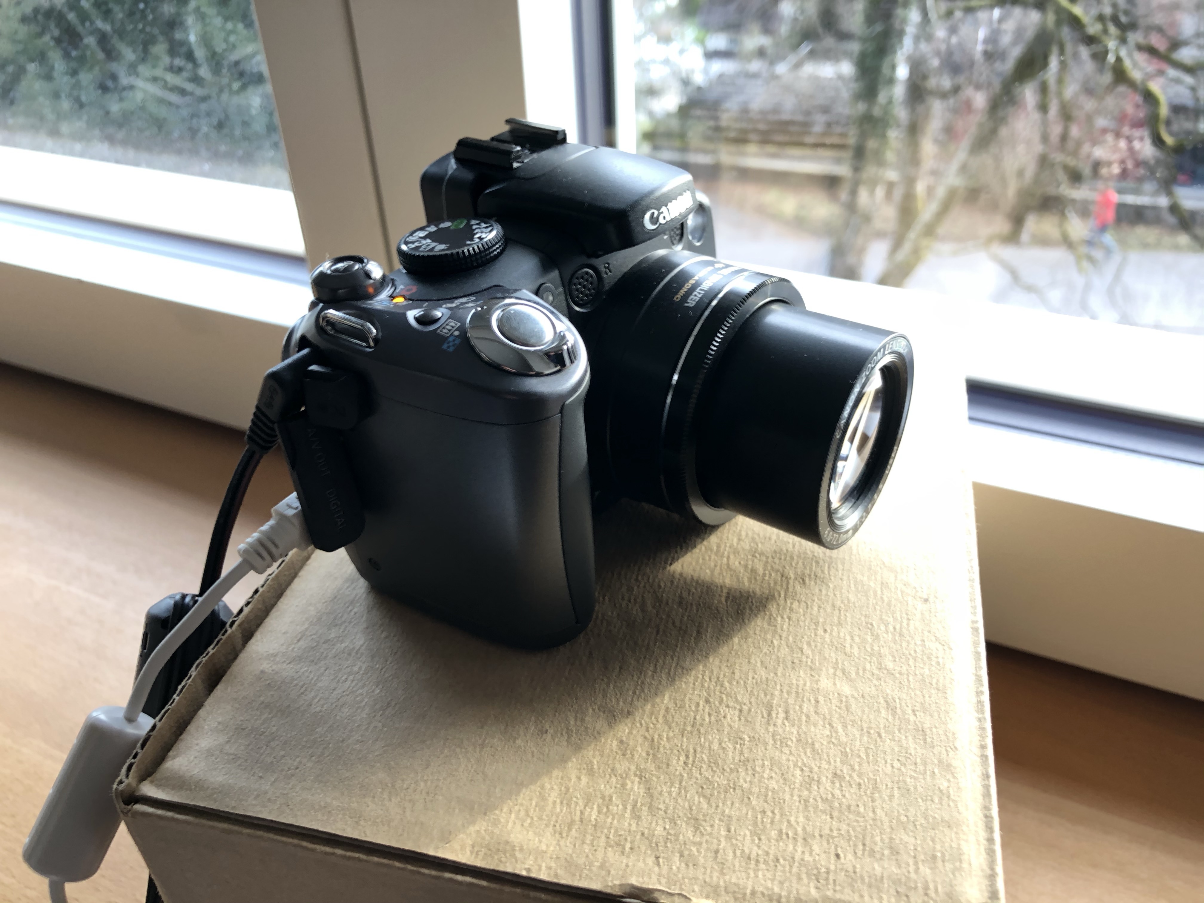
For some years I used a RPi based webcam (with the PiCam module). The produced images were all right but then, there was the moment where I wasn't satisfied with the quality any more. I decided to make a high-resolution Webcam.
The following parts were used:
Supplies
- 1 RPi 3, Model B, V1.2 (bought locally ~30$)
- 1 Canon Powershot S5 (bought on a secondhand online platform for around 20$)
- 1 Power over Ethernet Splitter: PoE to 12V/9V/5V: (TL-POE10R: PoE Splitter), ca. 12$
- 2 Step-down converters 1.5..35V to 1.5 .. 35V: (DSN6000AUD), 2x 3.5$
Prepare RPi
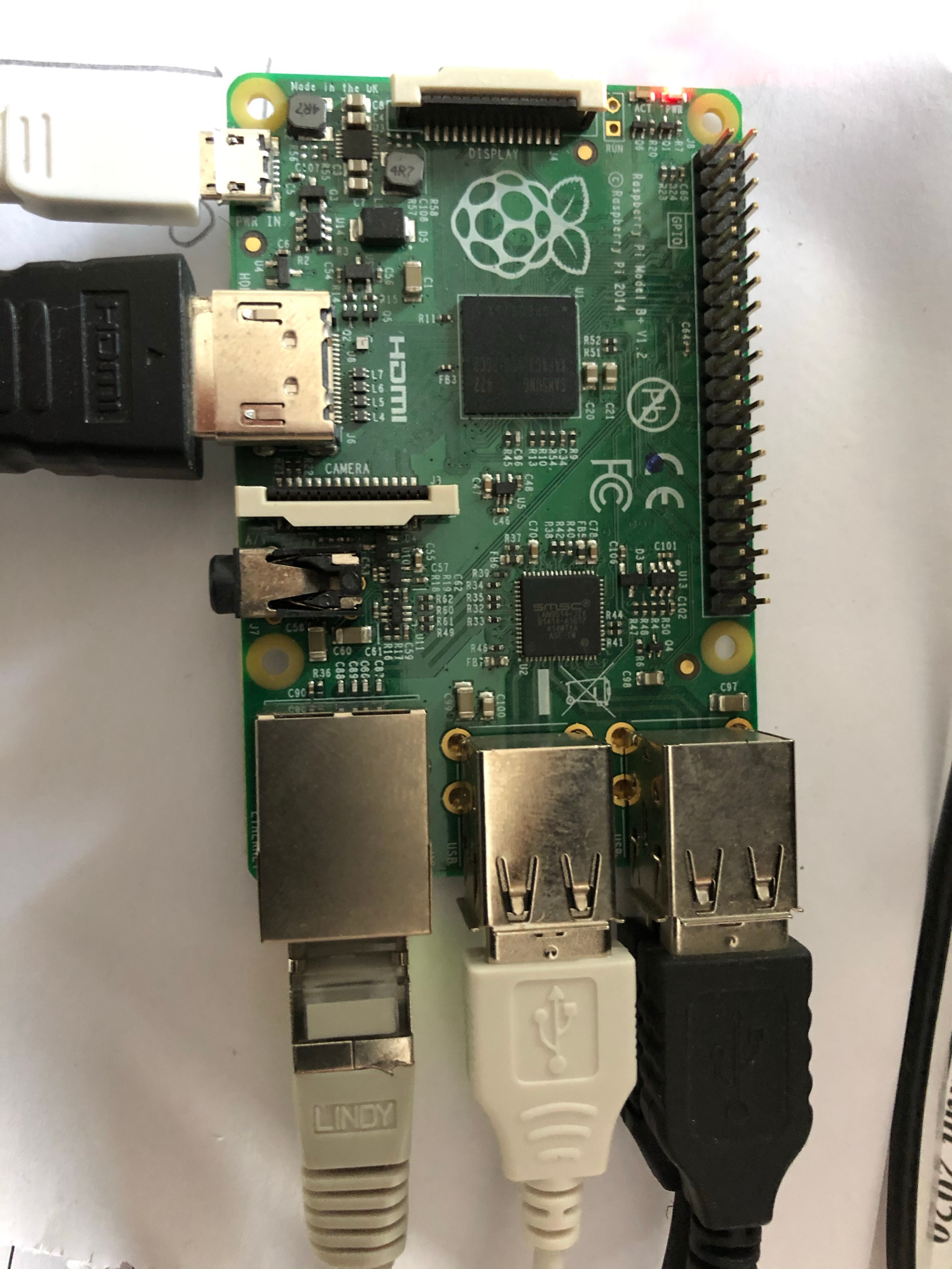
I'm not going to describe the preparation of the RPi. There are probably thousands of Instructables and howto's showing this step.
As a result, you have a ready RPi with raspbian of a current version.
Personalize the RPi
Now for the more interesting steps.
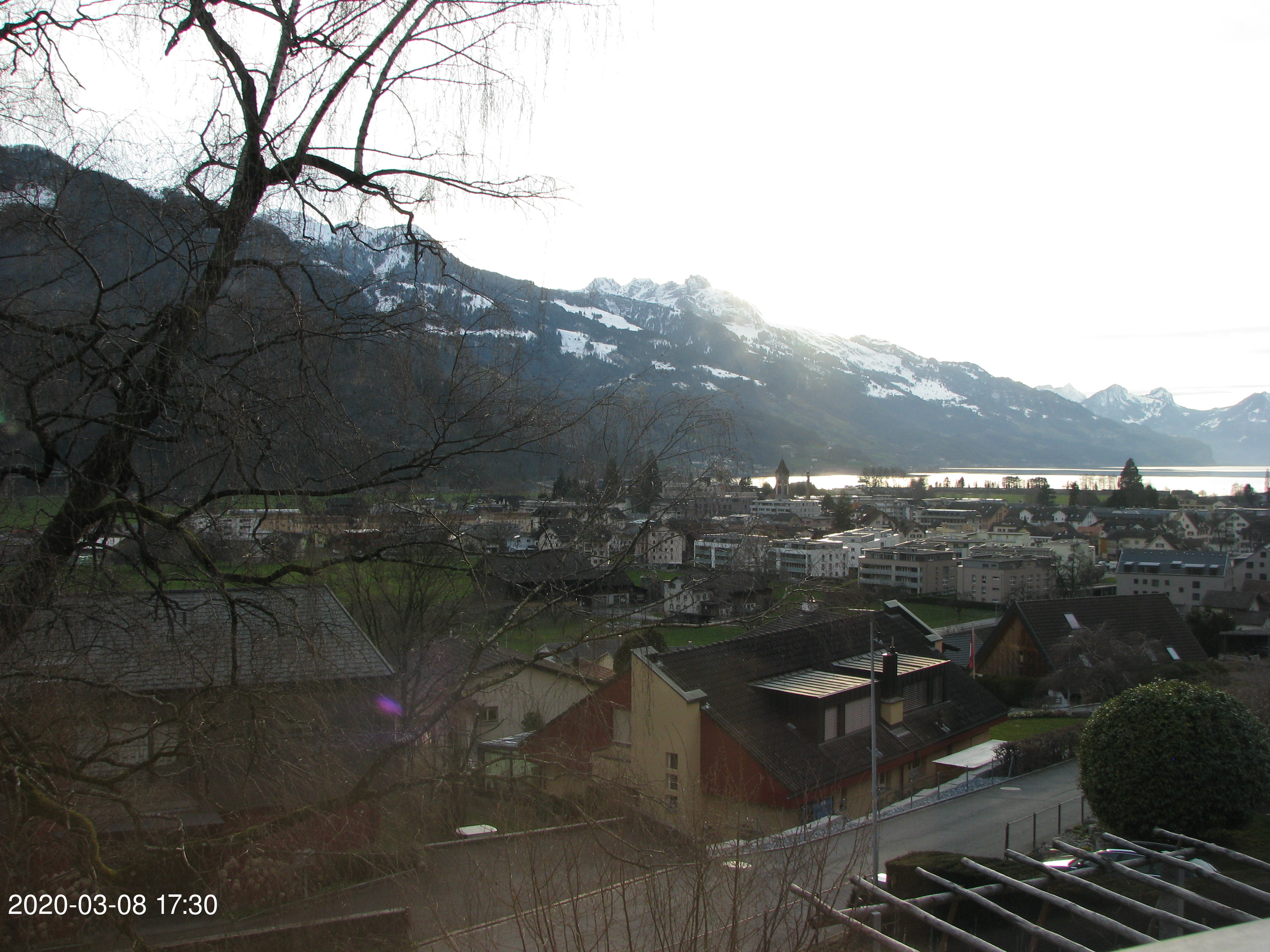
The idea behind the whole exercise is: take pictures every 10 minutes, store them onto the network attached storage (a Synology NAS), print the date and time on the image and, voilà.
The current image is available over the web as the folder on the NAS is the one which is accessible from the internet.
First the RPi has to mount the available share on the NAS where the picture is to be stored. Therefore the file /etc/fstab had to be adapted and the following line was added:
# mount the NAS<br>192.168.1.2:/volume1/web /mnt/nas2/web/ nfs vers=3,rw,soft,intr 0 0
If your going that direction, use your own proper addresses of NAS. As an alternative, you could also save the file locally on the RPi and access it directly. In that case forget this alteration of /etc/fstab.
For taking pictures I used gphoto2 and the following simple script:
#!/bin/sh
#kill any ghoto2 process possibly accessing the USB bus
pkill gphoto2
#take the picture with gphoto2
gphoto2 --capture-image-and-download --force-overwrite --filename /mnt/nas2/web/test.jpg
#insert date and time into picture
TEXT=`date +"%F %H:%M"`
convert -font helvetica -fill white -pointsize 70 -draw "text 20,2350 '$TEXT'" /mnt/nas2/web/test.jpg /mnt/nas2/web/test.jpg
This script is being stored as
/home/pi/take-picture.sh
make it executable by
chmod a+x /home/pi/take-picture.sh
Now attach the camera with a USB cable and power the camera.
If the storage of the camera is mounted automatically, you have to suppress that as gphoto2 can access the camera if it is in the so called PTP mode. You can suppress the automount on the desktop of the RPi.
Execute the script and the camera should take a picture.
You'll get a response like:
pi@picam2-walensee:~ $ ./take-picture.sh
Neue Datei ist in /store_00010001/DCIM/100CANON/IMG_0163.JPG auf der Kamera
Speichere Datei als /mnt/nas2/web/test.jpg
Lösche Datei /store_00010001/DCIM/100CANON/IMG_0163.JPG auf der Kamera
As, in my case, the image is now taken, stored and labelled with date and time, I can access it over the web.
To execute the take-picture.sh script all 10 minutes, I added an entry in crontab:
sudo crontab -e
add the following lines:
# take picture every 10 minutes<br> */10 * * * * /home/pi/take-picture.sh
This is going to execute the script /home/pi/take-picture.sh every 10 minutes (first */10). As we edited the crontab with "sudo", the crontab is being made for the superuser and the script is being executed with the rights of the superuser. This could probably also be done as the user 'pi'. I didn't try it. In that case, the command to edit the crontab of the user pi would be "crontab -e".
Case
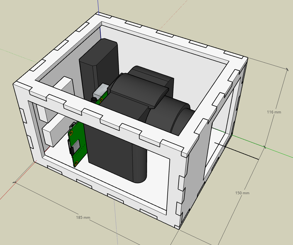
To determine the size of the case for the webcam, I constructed the whole thing in Sketchup. I made I rough model of the camera in the ON-state (lens is longer than in the OFF state) and added all the needed electronic components: Step-down-converter from PoE to 12V, 12V to 7.5V (for Camera), 12V to 5V (for RPi).
In front of the lens is the opening which will be closed with a piece of glass. The top and side opening are meant for mounting the parts and for maintenance.
Bottom plane (not visible here):
The bottom hole is for the ethernet cable and the slit is for the screw to fix the camera.
Perparing for Conversion to DXF
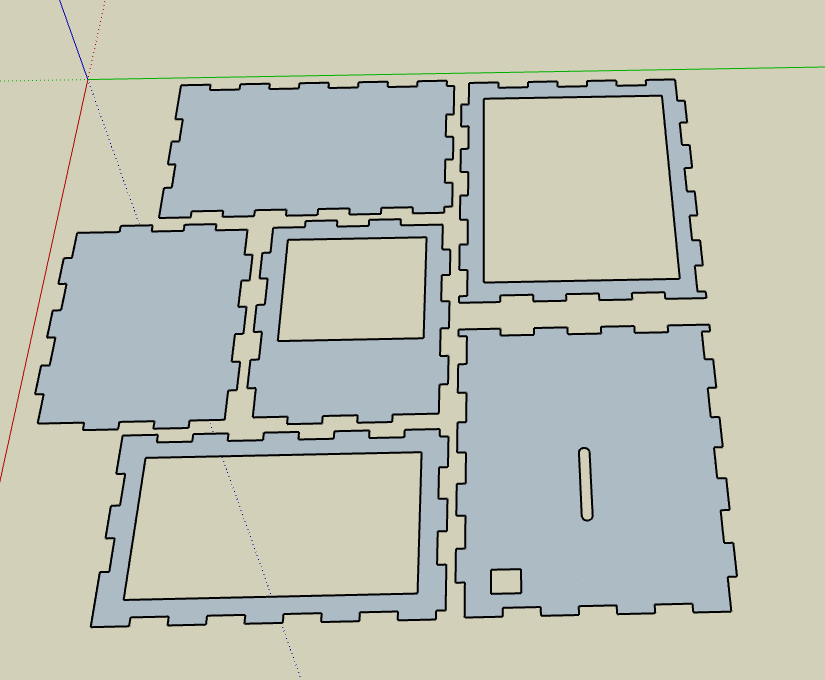
As I do only have a basic Sketchup account I had to find a way to convert the plan to a DXF file for laser cutting.
Therefore, I placed all the walls flat, one besides the other and removed the 3rd dimension. After that, I downloaded the resulting STL-file.
Conversion to DXF
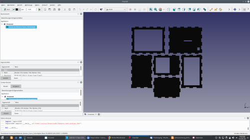
For the conversion to DXF I used freecad. Import the STL File and export as an DXF. This file was then sent to the shop to cut the 5mm plywood.
Oh-oh
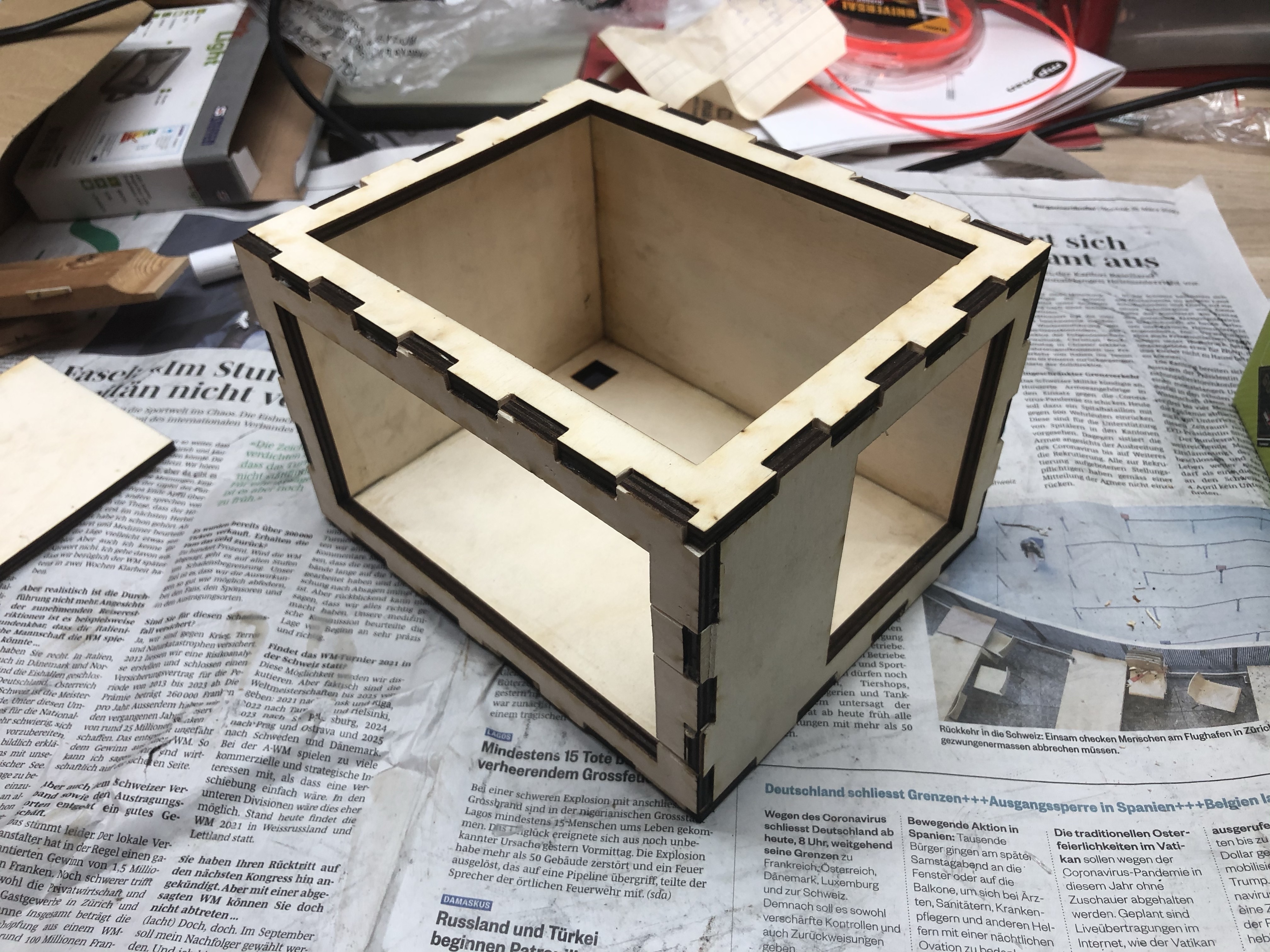
Some days later, the pieces were cut.. but my oh my. I somehow made a mistake converting the sketchup-data to the dxf data. I had to scale them and therefore: I had to use the rasp to make the parts fit. What a mess...
But in the end I could glue all parts together and finally painted them white to reflect as much sunlight as possible. (there is no cooling foreseen.)
Lids
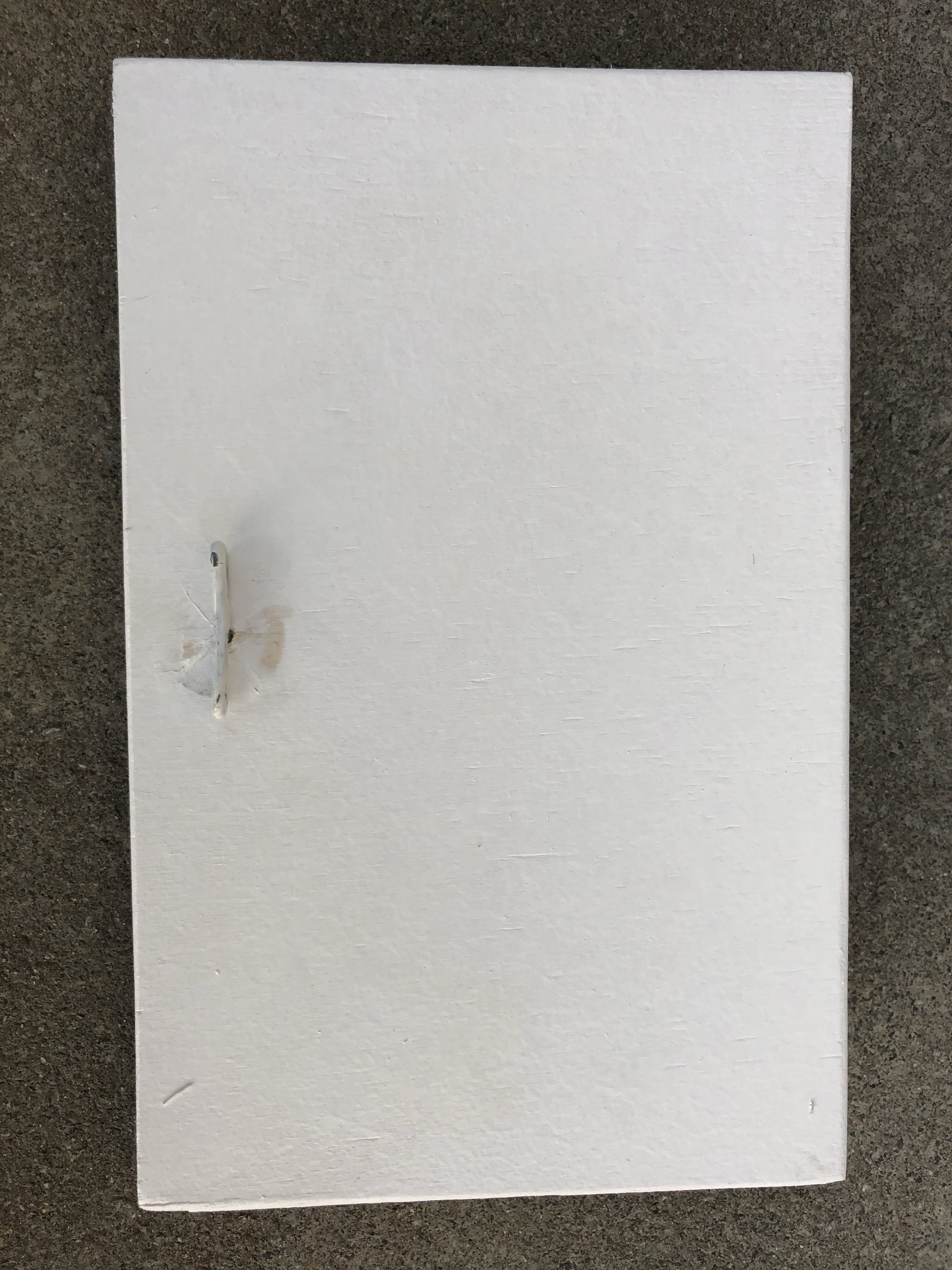
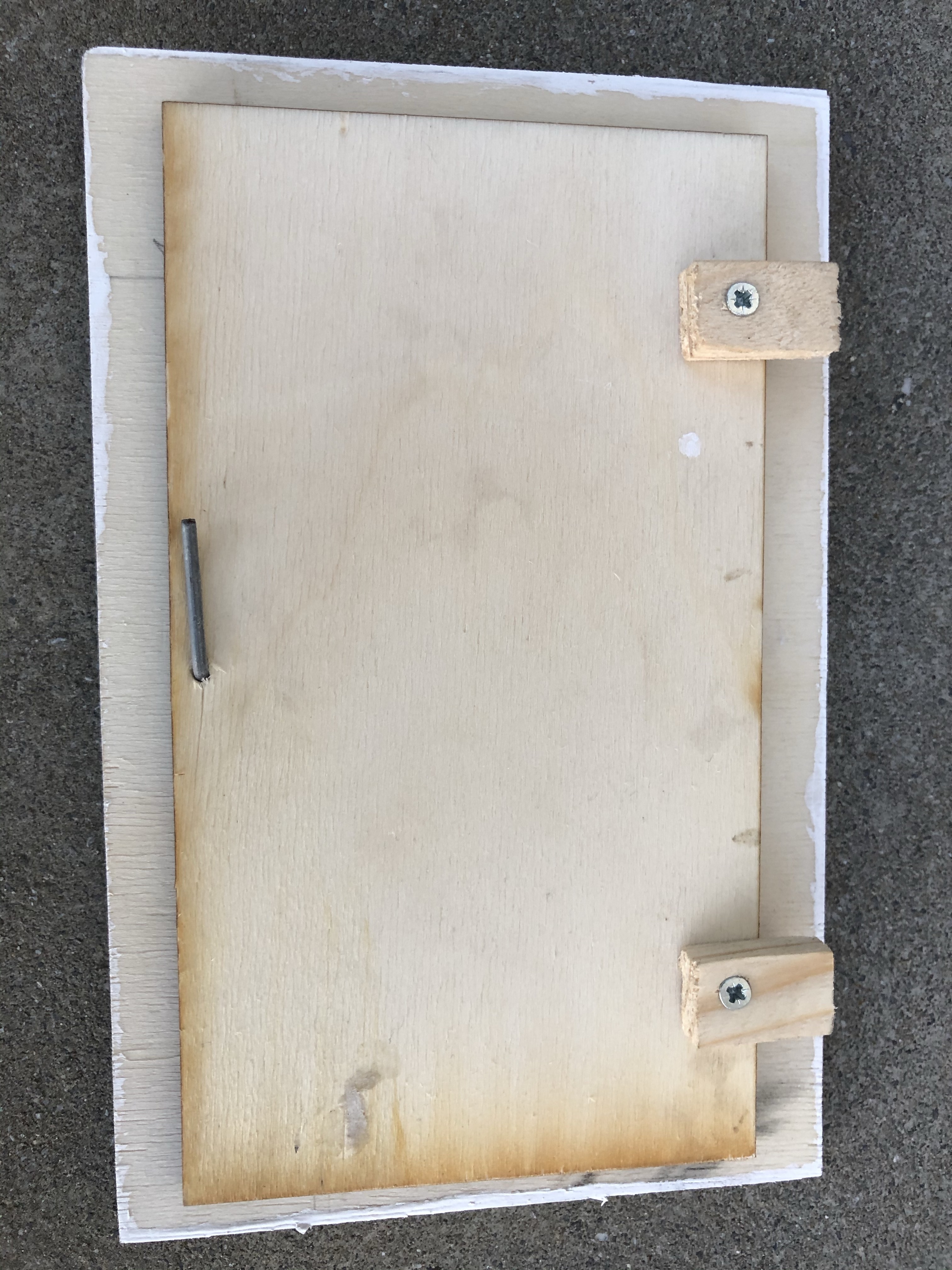
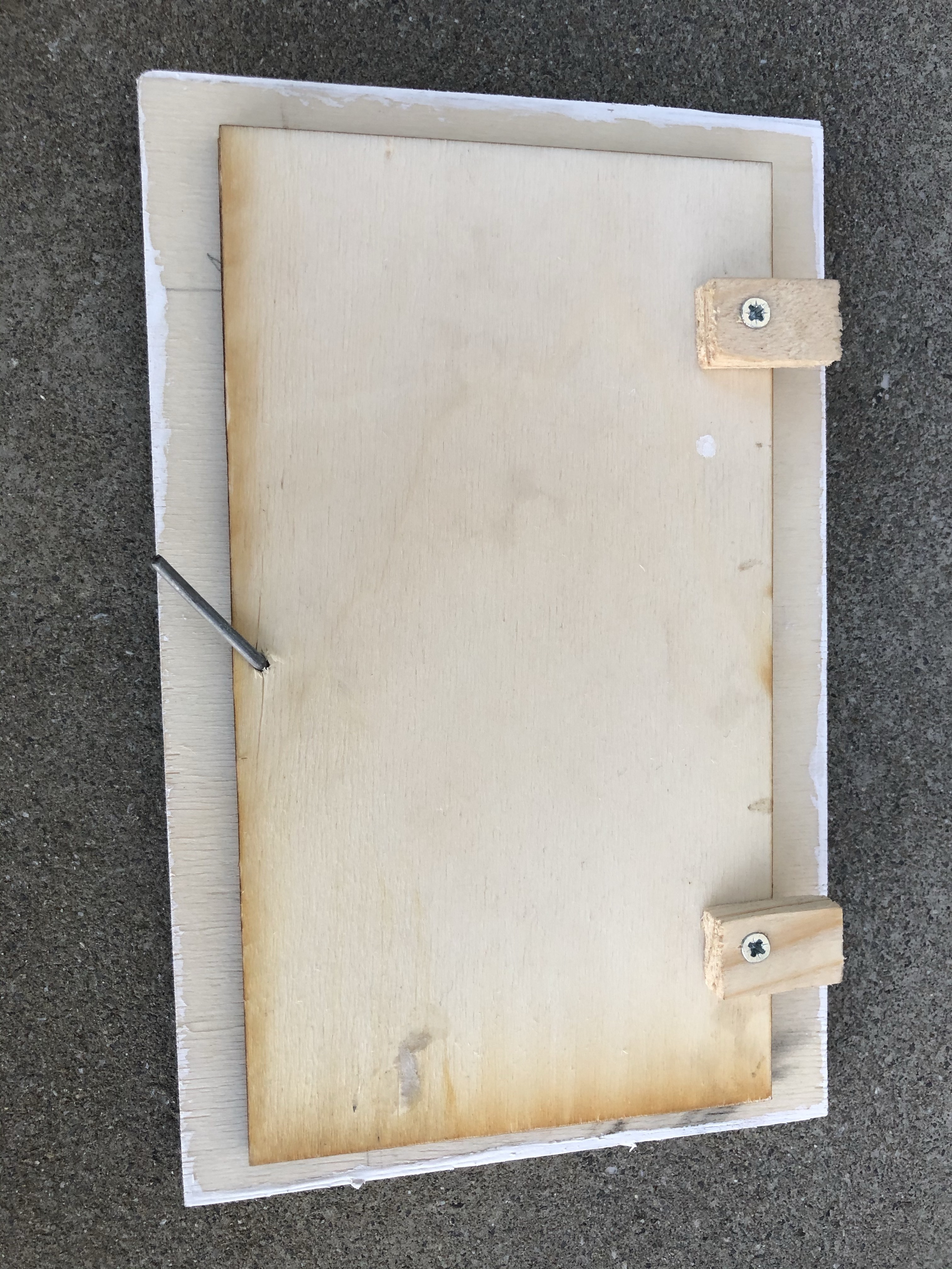
As I have already some experience with "not working" webcams, I decided to have easy access to the parts in the case.
Therefore I designed very simple lids. For the side-lid and for the top-lid, the mechanism is very easy. It's just a piece of bent wire which can be turned about 30° to lock the lid in place.
Access the Images
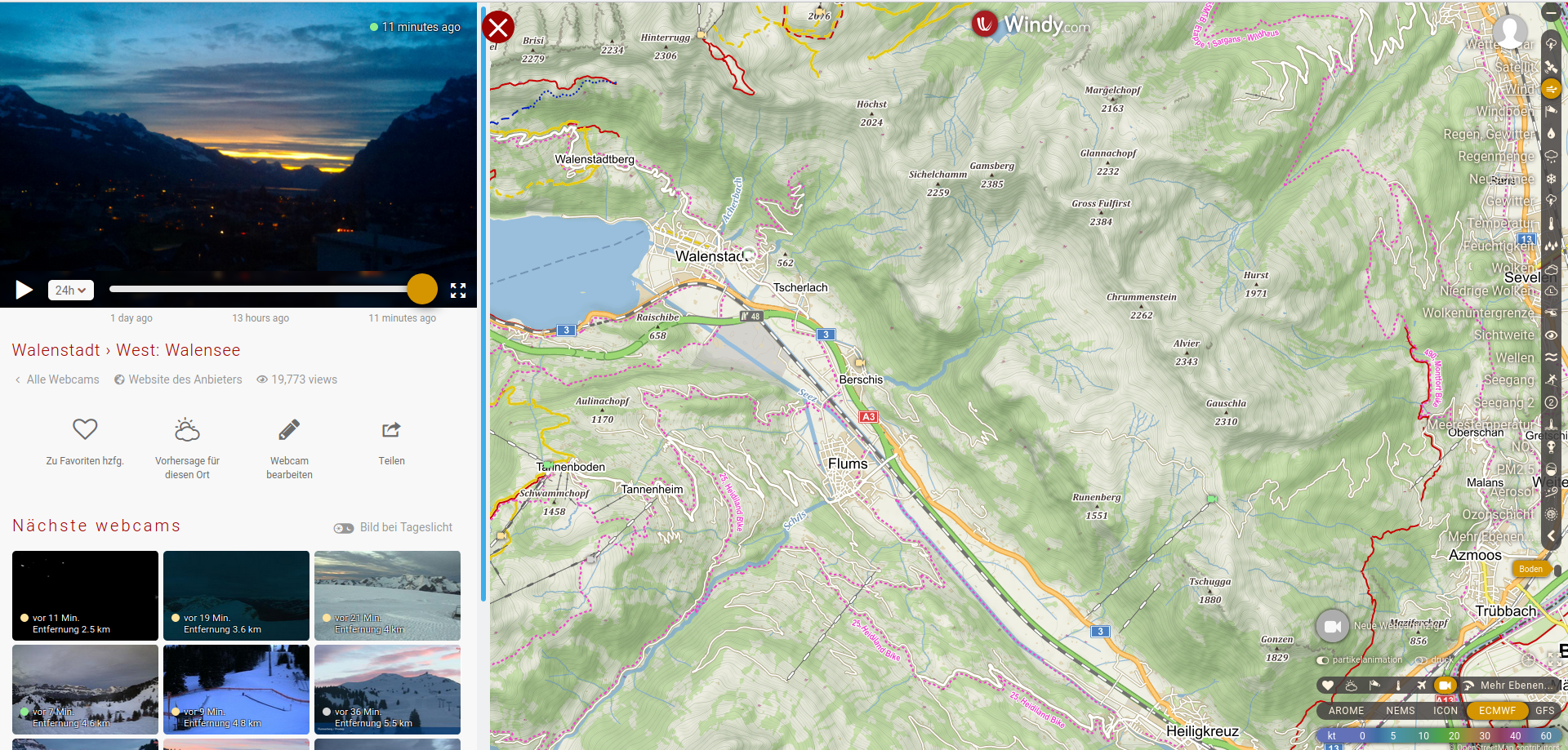
The images can be accessed via the following link:
https://www.windy.com/de/-Webcams/Schweiz/Sankt-Ga...
This are still the images of the old webcam. The new ones will follow.
Mounting the Camera
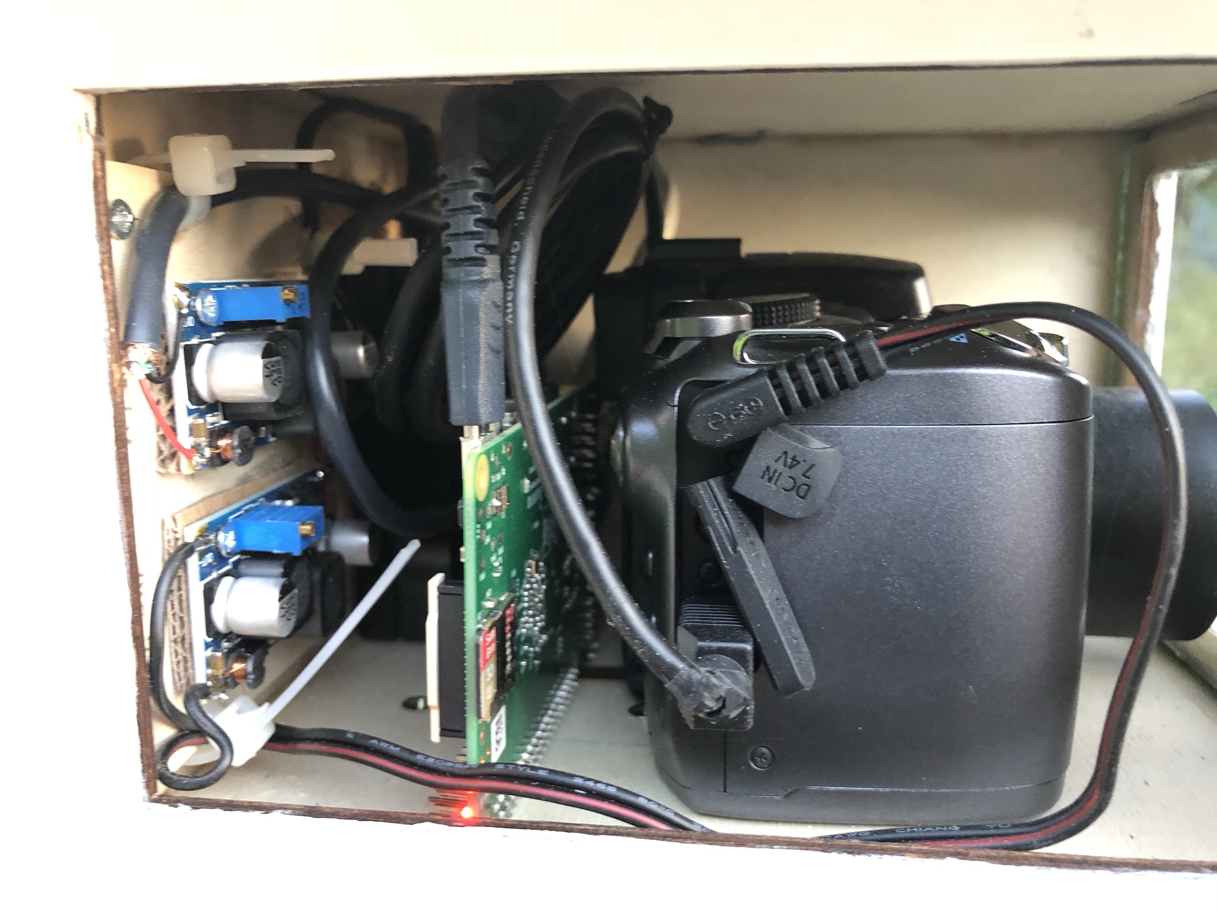
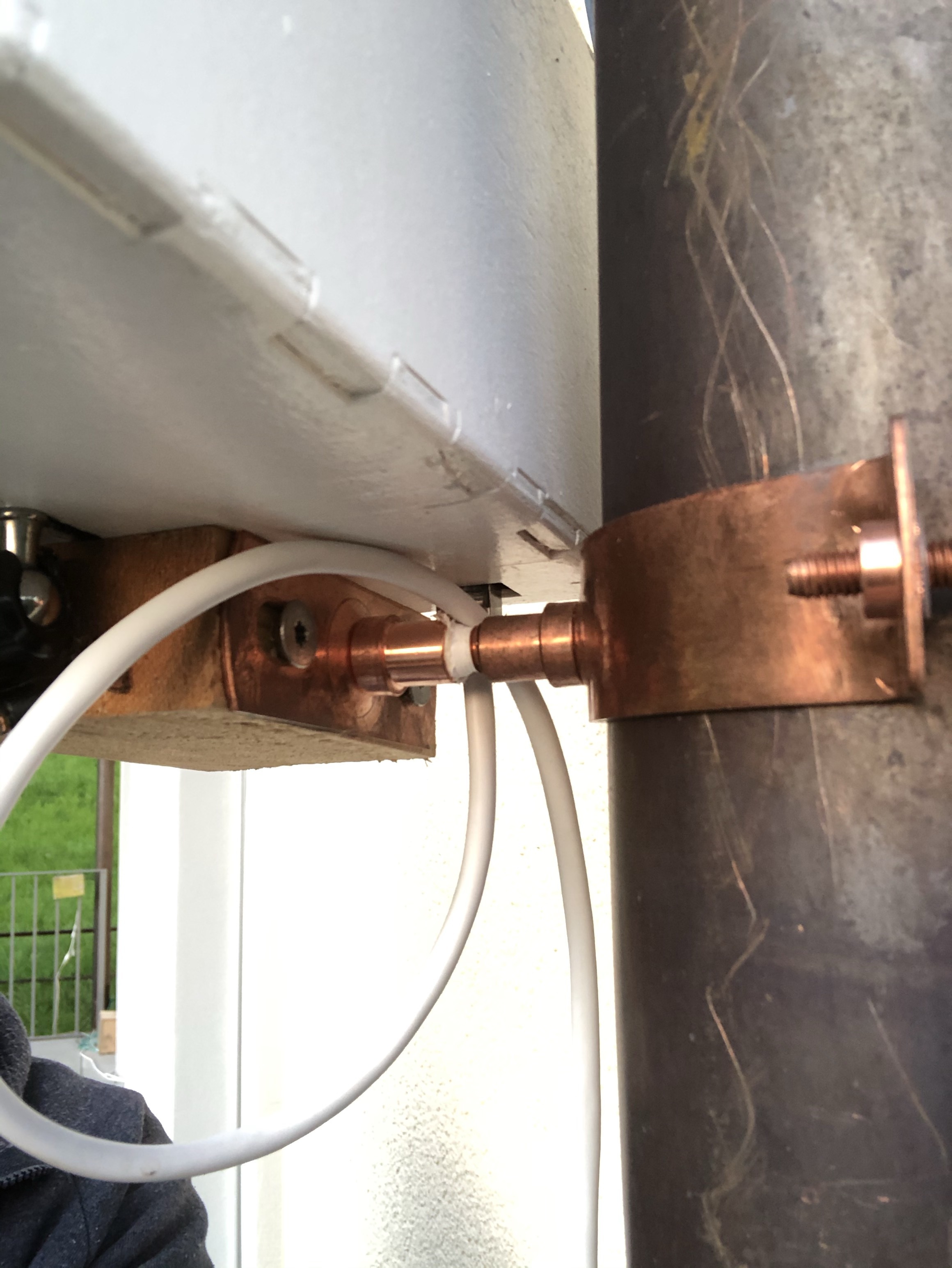
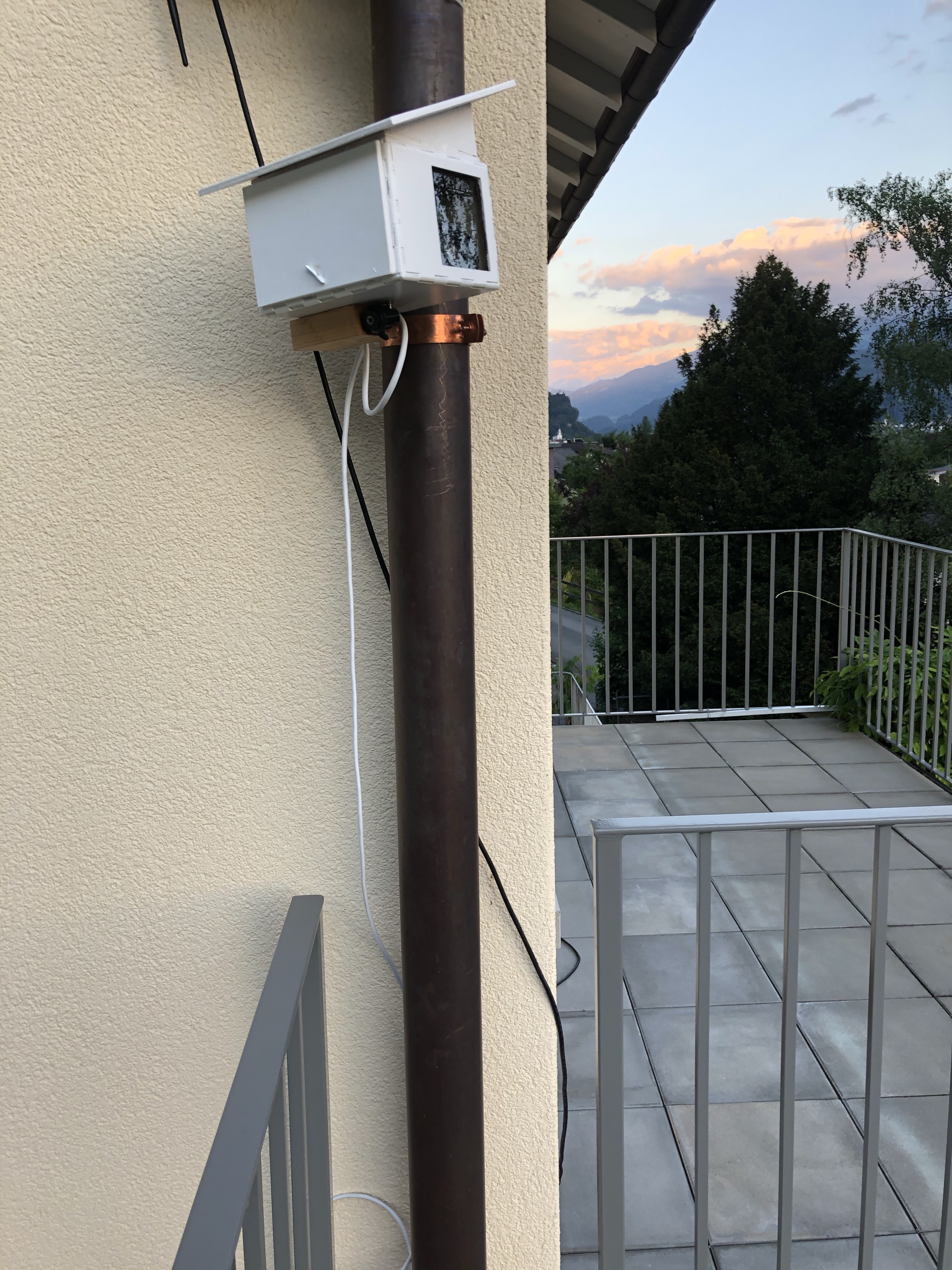
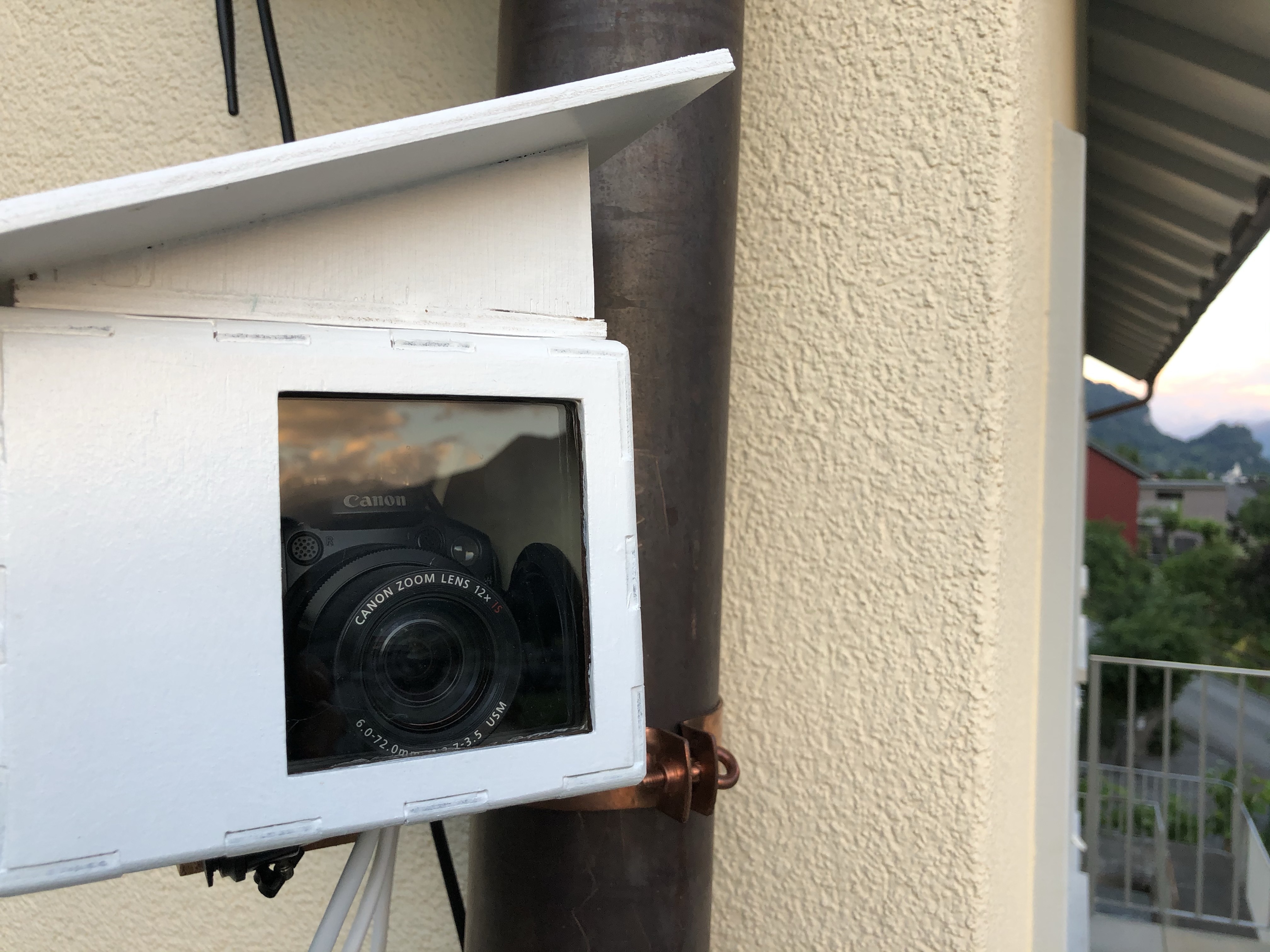
After the installation of all parts in the case, it was time to mount it.
As I normally do, I attached the whole case to the rainwater pipe using a bracket which is normally used to attach a drainwater pipe to a wall. I just used it the other way round.
As you can see in the last image, the window of the case could have been much smaller, but still - it seems to work.