Heavy Duty Giant Glowing Pushbutton
by CLClab306 in Circuits > Arduino
866 Views, 11 Favorites, 0 Comments
Heavy Duty Giant Glowing Pushbutton

Who can resist smashing a big pushbutton? If you have that urge, this project is for you!
I have been working on a game project in which players need a big pushbutton that provides some kind of visual feedback. Although commercially available pushbuttons might be hackable for this purpose, I decided it would be more fun to make my own. That way, the button could provide colored feedback under program control, and it could be made durable enough to withstand enthusiastic smashing by game participants.
This Instructable describes how to make a large circular pushbutton (110-mm diameter x 50-mm high) from four 3D printed parts designed in Fusion 360. The hollow translucent dome of the button piece is illuminated from below by a single RGB LED. Downward motion of the button dome activates a microswitch that, along with the LED, can be easily connected to your favorite microcontroller. Some soldering is required for the electronic parts, but the overall process of assembling the button is otherwise easy.
To illustrate the pushbutton in action, this Instructable also includes an Arduino sketch that detects and counts button presses, determines how long the button was pressed, and lights up the button's dome.
Supplies


Gather the following supplies:
- Arduino Uno microcontroller (or equivalent) & USB cable
- Microswitch with roller lever arm
- WS2812B RGB LED Pixel 5V DC
- Assorted Dupont Breadboard Jumper Wires
- 5V-1A Power Supply with 8 DC plugs
- 4-inch zip ties
- 3D Printer filament--Natural Translucent PLA or Clear T-Glase for button; any color PLA for other parts
- solder, heat shrink, and hot glue sticks
Tools


Tools needed for this project are listed below. I used a Lulzbot TAZ-5 3D printer, but any 3D printer with a build-base bigger than 110 x 110 mm should work.
- 3D-printer
- soldering iron & solder
- wire stripper
- wire cutter
- needle nose pliers
- hot glue gun & glue
Print 3D Parts


The four parts were printed in the orientation shown in the pictures. The layer height was 0.25 mm for the Button, Base and Lid (20% infill). For each of the 4 springs, layer height was 0.18 mm (100% infill). I did not use any supports. The spring was designed with an extra closed ring at the bottom to facilitate adhesion to the print bed. However, if you have adhesion problems, you may need to add a brim or raft. That's not a problem because the springs were designed longer than needed and the bottom part of the coil will be removed later using a wire cutter (Step 5).
Natural translucent PLA or clear T-Glase was used to allow illumination of the button’s dome. Any color PLA (or PETG) is fine for the remaining parts. Aside from removing stray strings from the holes on the lid (including the hole in the middle on the bottom) and sanding/filing rough edges, very little post-processing of the button, base or lid was needed.
I decided to try 3D printing the springs after failing to find wire springs of the right size in local hardware stores. To be honest, I was surprised that I was able to design plastic springs that worked as well as they do. If you have better luck finding appropriate wire springs locally (or online), you can easily substitute them for the plastic springs.
Design Notes: The four vertical shafts around the perimeter of the base are two-tiered to prevent the button piece from bending the roller arm on the microswitch. The ledge on the lower tier allows the button to go down far enough to close the switch, but no further. The screw-top lid makes assembly and access to the inside easy for anyone who's ever used a mason jar. If that turns out to be too easy for your users, you can always drill a hole through the side of the assembled lid and base and insert a screw to make disassembly more difficult.
Fusion 360 Design Files: Separate design files are included for the spring and for the main button assembly. My steps to the final design were somewhat circuitous, so let me know if I left anything out.
Solder Wires to Switch & LED


The next step is to solder the electrical parts that will be housed in the base. This process is broken down as follows:
- Prepare four 8-inch Dupont jumper wires for soldering: To simplify the next few steps, select one red wire (for 5V) and one black wire (for GND); the other two wires can be any color (the pictures show green and yellow). Using the wire clipper, cut off the crimp connector & housing on one end of each wire, but make sure the other end has a female crimp pin & housing. Using the wire stripper, remove about 1/4 inch of insulation from the end of the wire. Use your thumb and forefinger to twist the wire strands as tightly as you can (see picture).
- Tin the bare wire tips with solder: The goal of this step is to coat the twisted wire strands with a thin layer of solder. I usually set the hot soldering iron on my mat, hold the bare wire against the solder tip, and try to let the heat of the wire melt the solder onto the wire (see picture). After the wires are tinned, use the wire cutters to trim the wire tips back to about 3/16 inch.
- Prepare two additional black wires for soldering: Cut 4-inch and 8-inch pieces of black wire, strip the insulation from both ends, twist the wire strands, and tin all four wire tips as described above. These pieces can be made from standard jumper wires after clipping off the connectors or by using any black 24-gauge stranded wire.
- Solder yellow wire & 4-inch black wire to the microswitch: Before soldering, put some short (~6-7mm long) pieces of heat shrink over each wire and temporarily slide it down to the other end of the wire. Use the needle-nose pliers to bend the tip of the yellow wire into a V-shape and insert the wire through the middle solder lug on the microswitch (marked "NO" for "Normally Open"--see picture). Pinch the wire tightly against the lug with the pliers. Then, holding the hot iron tip against the wire and lug, allow the heat of the wire and lug to melt the solder over the connection. Repeat this process to attach the black wire to the solder lug marked "C" (for "Common"). To provide stress relief, slide the heat shrink pieces down over the lugs and use a hot-air gun (or other heat source) to shrink them down to a tight fit. Finally, carefully use the needle-nose pliers to gently bend both wire connections toward the roller end of the microswitch (see picture).
- Solder wires to the RGB LED: Tape the LED to your work surface, making sure the solder pads on the side marked "D-in" are exposed. Next, take the red and green connector wires and the 8-inch black wire with no connector, and insert the tinned wire tips through a short piece of heat shrink big enough for all three wires. Trim the tinned wire tips to about 1/8 inch. Then: (a) heat each of the three solder pads long enough to melt a small mound of solder on each pad; and (b) solder the wire tips of the red, green and black wires to the solder pads marked +5V, D-in, and --, respectively. In each case, place the wire tip on top of the solder mound and carefully press down with the hot iron tip until the wire is embedded in solder (see picture). Since the solder pads are very close together, this may take several tries to avoid solder bridges between pads. Finally, push the heat shrink up to the LED and use your heat source to shrink it. To provide addtional stress relief for these connections, I also applied a coat of Bondic over the solder pads and junction with the heat shrink. However, this was probably not necessary since the LED will get covered by hot glue in Step 4.
- Solder the wire tips of all three black wires together: Create a pigtail solder joint by twisting the remaining tinned tips of the three black wires together, heating the twisted tips with your iron, and applying solder (see picture). Finish with heat shrink over the joint (see picture).
Doublecheck all your connections before going to the next steps. If possible, use a multimeter to test for continuity.
Attach Wired Parts to Base and Lid


The next major step is to attach the "wiring harness" created in Step 3 to the base of the Giant Pushbutton.
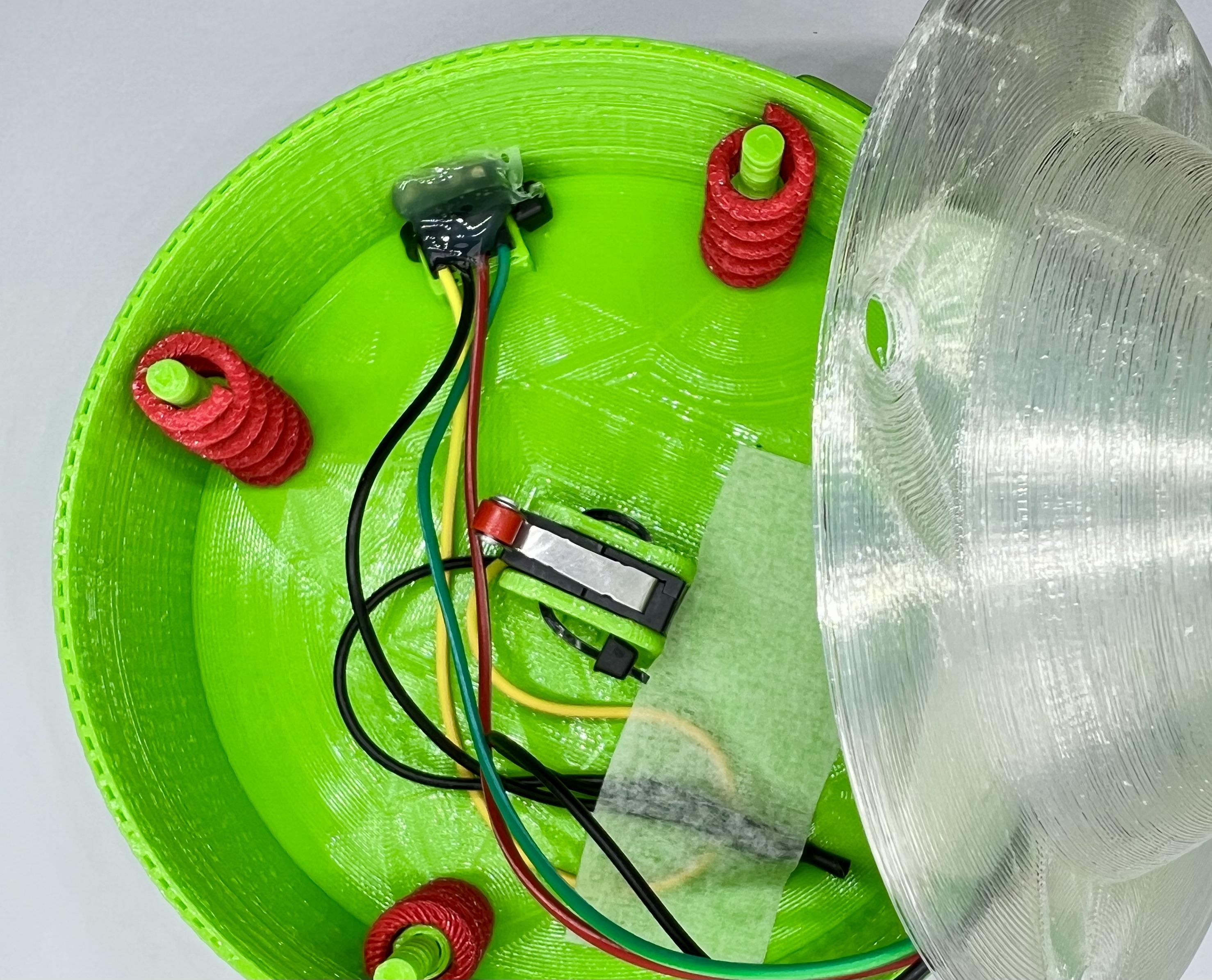
- Attach microswitch to base with zip tie: Slide the microswitch down into the switch holder with the roller arm and wires oriented as shown in the picture. Then, thread a 4-inch zip tie through the front and back holes in the switch holder and switch (see picture). I found it easiest to use the needle-nose pliers to direct and pull the zip tie. Get the head of the tie snug against the side of the holder, thread the tail through the head until it's tight, and trim the excess tail with wire cutters (see picture).
- Attach RGB LED to bottom of button dome: Place the RGB LED into the hole on the bottom of the button piece as shown in the picture. Temporarily hold the wires down with a piece of tape while you cover the LED, heat shrink and surrounding button with hot glue. After the glue has cooled down and set, re-tape the wires as shown in the picture so that they are not directed toward any of the perimeter holes.
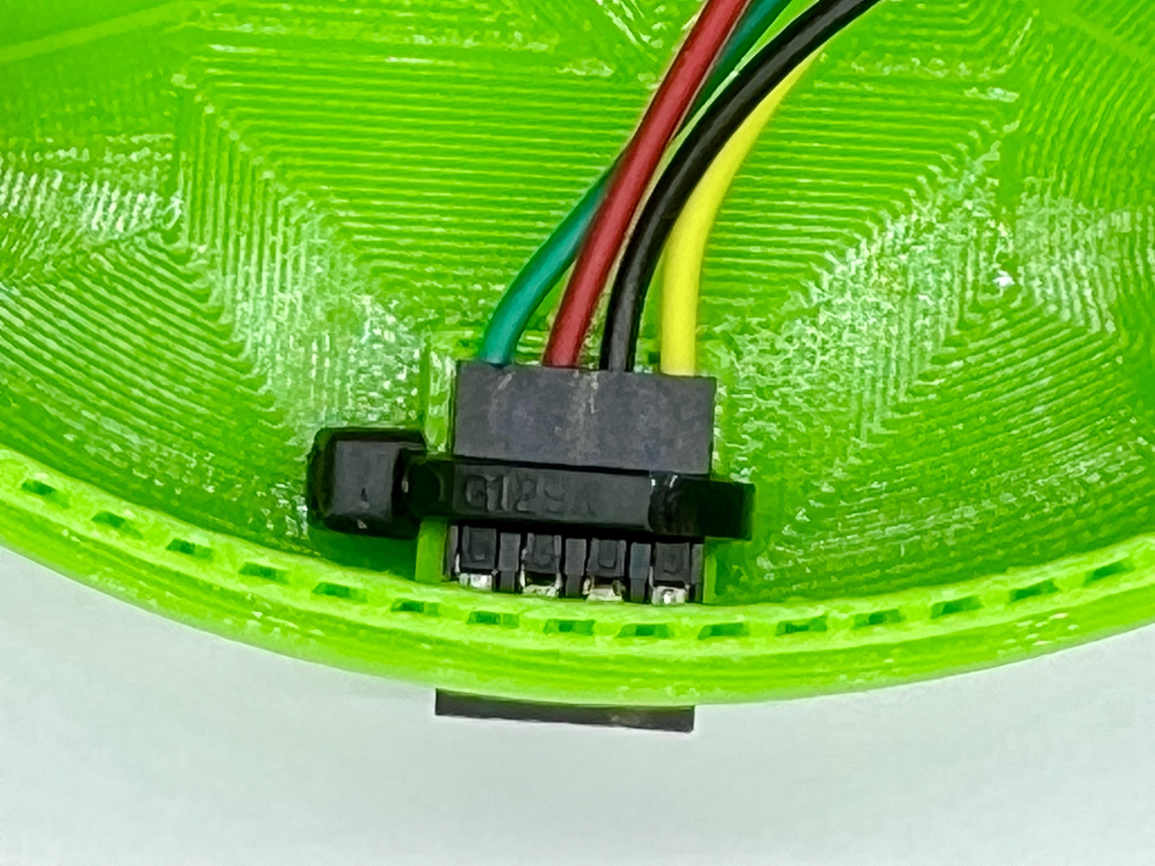
- Attach connectors to connector platform: The next step is to attach the 4 female connectors to the small platform under the hole in the base's side in the order shown in the picture (GRBY). If you have a housing for 4 crimp pins (which I did), I suggest removing each pin from its original single pin housing and inserting it in the 4-pin housing. As an alternative, you can tightly shrink some heat shrink around all 4 pins to keep them properly aligned. Then, insert a cable tie into the hole in the small platform. Feed the tail into the head just enough to latch the tie, but do not tighten yet (see picture). Next, place the connectors on the platform so that the tips poke out through the hole, tighten the zip tie, and cut off the excess tail. Finish up by coating the connector, zip tie, and nearby base wall with hot glue.
- Tape wires: To minimize interference with the springs and lever arm, I draped the pigtail joint and excess yellow wire in a counterclockwise direction from the front of the switch and taped them to the base (see picture).
Final Pushbutton Assembly

The Fusion 360 animation shows how the printed parts fit together (detailed description below).
- Trim the springs: Use the wire cutters to remove the circular ring at the base of each spring. Continue to trim the ends until the height of each spring is about 30 mm. Slide the springs over the 4 vertical shafts. The top of each spring should be about 1-2 mm below the top of the shaft.
- Center the button dome on the base: Align the 4 holes on the button over the 4 vertical shafts in the base. Turn the button in a counterclockwise direction so the hanging LED wires are directed away from the lever arm.
- Screw lid onto the base: To maintain button hole alignment, keep the button pressed down on the springs until the lid is completely screwed on.
- Label the pin assignments for the female connectors: I finished button construction by attaching a label above the connector hole to show how the 4 connectors were assigned. At this point, the button should be ready to connect to your microcontroller (Step 6).
Upload Demo Program to Arduino UNO


The program sketch was created and uploaded to an Arduino UNO using Arduino IDE 2.03. If you are not familiar with the Arduino IDE, you might take a look at one of the many nice tutorials on this topic before going further (e.g. lesson-0-getting-started). In addition to downloading the Arduino IDE to your computer, you will need to install two Libraries using the IDE's Library Manager: TimerOne (Version 1.1.0) and Adafruit_NeoPixel (Version 1.11.0).
- Download/Install the Arduino IDE: HERE and install on your computer (Windows or Mac OS).
- Install the two Libraries: Open the IDE and click on the Library Installer icon (see picture) to search for and install the 2 libraries named above. Type the Library names into the search window and click on INSTALL when you find the correct Library (see pictures).
- Download/Open the Giant Button Demo sketch: Download GiantButtonDemo.ino to your computer and open it by double-clicking on the file icon.
- Connect the UNO to your computer with USB cable.
- Select Board and Port: Click the downward caret to open the dropdown menu on the IDE menu bar, then click "Select other board and port..." as shown in the picture. Select "Arduino Uno" and the appropriate USB port in the popup menu (see picture). Click OK when finished.
- Verify the sketch to check for errors: Click the "Verify" icon in the IDE menu bar (see picture). The IDE will then attempt to compile the sketch, which should result in no error messages (unless the sketch was modified). Correct any errors before continuing.
- Attach jumper wires between button and UNO: Use male-male jumper wires to connect the button connectors to the appropriate header pins on the UNO. The connections are shown in lines 5-8 of the sketch.
- Upload sketch from computer to UNO: Click on the "Upload" icon in the IDE menu bar (see picture). The IDE will compile the sketch again and upload the compiled code to the UNO.
Downloads
Smash That Button!


If everything uploaded correctly, the button dome should be continually illuminated with a rainbow color sweep. Pushing the button should produce five white flashes before resuming the color sweep. Button presses are ignored during the white flashes. Click on the Serial Monitor icon in the upper right hand corner of the IDE window to view incoming pushbutton data. Right after releasing the button, the Serial Monitor will show the duration of the button press (in msec) and the total number of presses since the UNO was last powered up or reset.
The sketch is commented to explain what's going on in each section. To deal with the problem of switch bounce, the TimerOne Library was used to set up a clock interrupt function that checks the status of the switch input pin every 10 msec. The sketch will only count an input as a new button press if the switch was closed on the last 10-msec clock pulse, but is now open. Thus, to be counted, a switch closure must last at least 10 msec, which is longer than the typical duration of switch bounce. As you will see by running the sketch, most presses with this pushbutton are much longer than 10 msec (50+ msec). In other words, by using a 10-msec clock interrupt, you can avoid switch bounce problems and you need not worry about missing any button presses. Of course, this strategy necessarily imposes a slight delay (< 10 msec) between the precise moment of switch closure and the program's ability to act on that input, but that kind of precision is probably not an issue for most Maker projects.
The sketch illustrates some additional advantages of using a clock interrupt function. For example, by counting the number of clock interrupts between the onset and offset of the switch closure, the program can measure button press duration with 0.01 sec resolution. Also, the number of clock interrupts can be used to time output events like blinking the UNO's built-in LED every 250 msec and updating the rainbow color sweep every 10 msec. In this sketch, the clock interrupt makes it look like the UNO is doing 3 different things "simultaneously": (a) monitoring button presses, (b) blinking the built-in LED, and (c) displaying a rainbow color sweep on the button dome. It would be much more difficult to do all three things in the main loop function using the delay() function for timing.
There are many uses for giant pushbuttons beyond counting presses, measuring their duration, and blinking lights. Pushbuttons are an ubiquitous feature of many Maker projects--a giant glowing pushbutton will add fun to its basic function. The Giant Pushbutton can be used as a separate component of a larger project or, in this case, the pushbutton's large base can actually be used to house a small microcontroller (e.g., ATTiny84, ATTiny85, ESP8266, ESP32) and a rechargeable Li-Ion or Li-Poly battery, making a self-contained portable Giant Glowing Pushbutton.