Heads Up


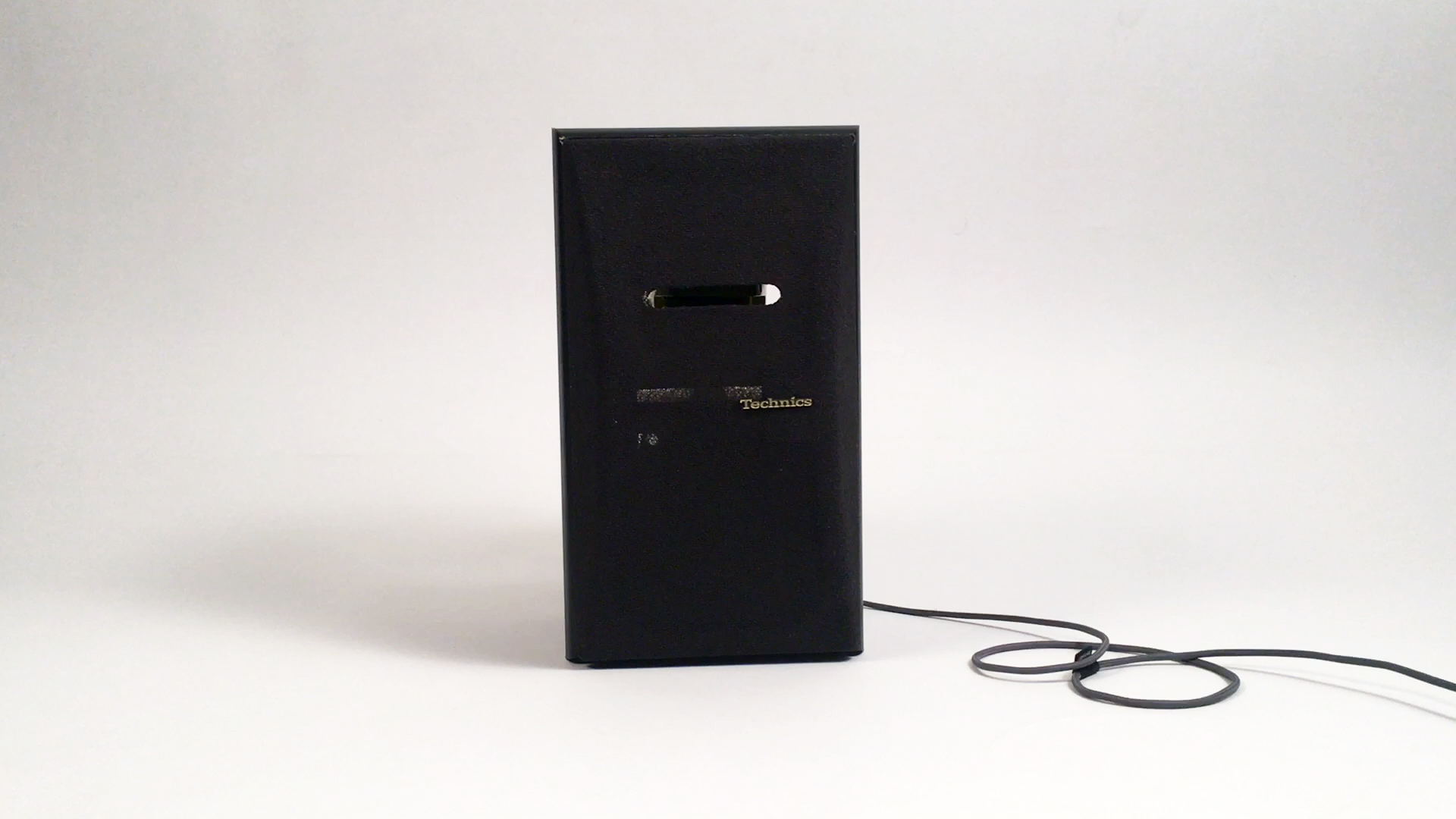
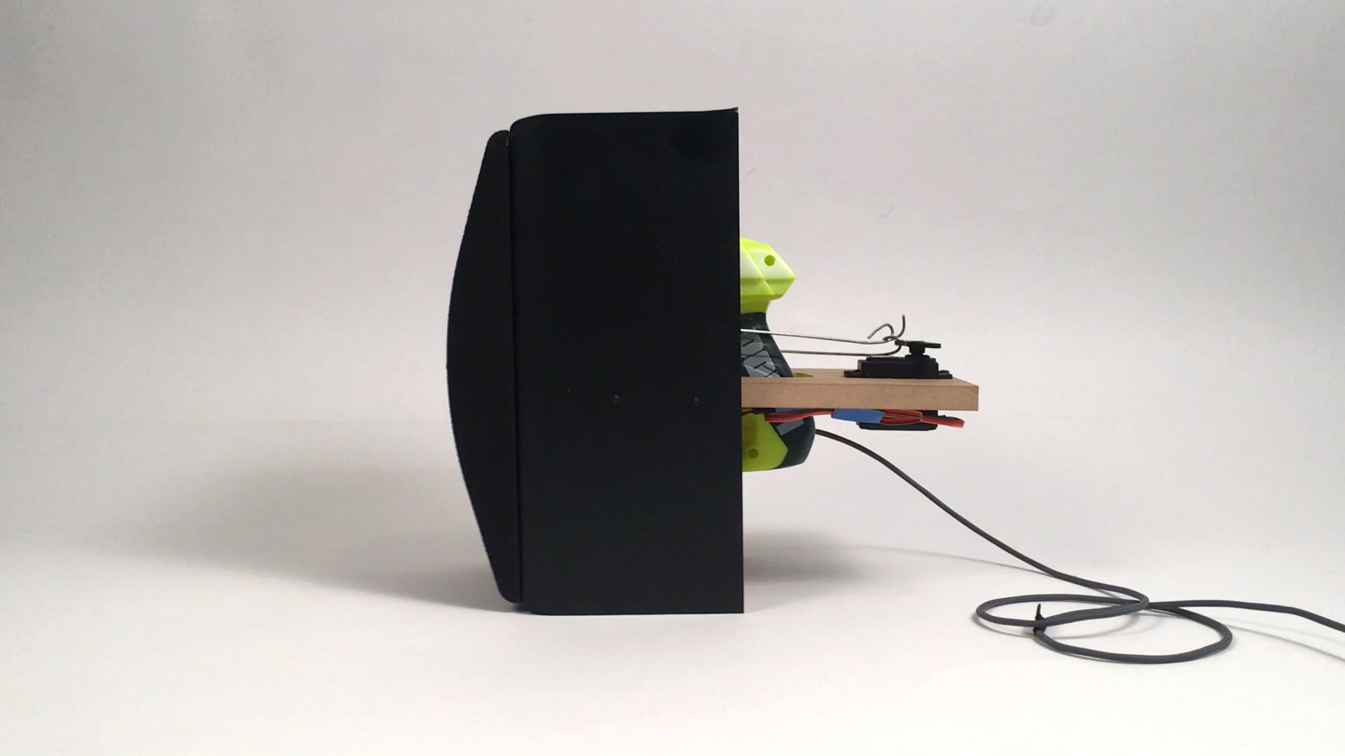
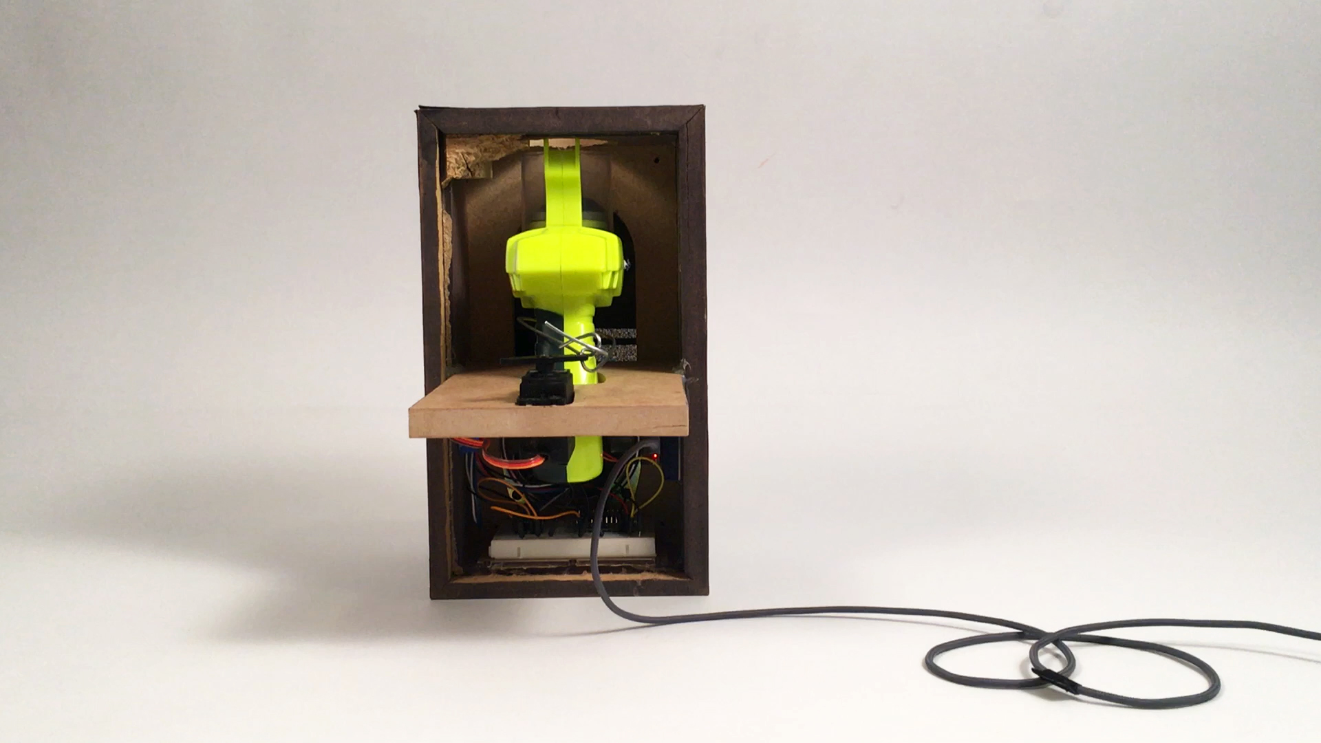
In this project, we will hide a foam disc shooter and a small speaker connected to an arduino wifi board inside an old speaker box. The foam disc gun and speaker audio sequence will be activated through the IFTTT.com service. The IFTTT.com service has a wide array of options that can pull information from the internet to send a trigger to your arduino board. I have chosen to use Twitter as my activation method, but there are many options out there for customization.
And.. for this project, we have setup the sequence to pull the trigger of the gun..... then, shout "HEADS UP!".
Materials Needed
Electronic Components:
Material:
- Old speaker box (thrift store is great option)
- Foam Disc Guns
- Structural wire (XX gauge)
- Double sided tape
- Sandpaper
Tools:
- Soldering Iron
- Screwdrivers
- X-acto blade
- Drill
- Saw
- Sandpaper / sand drum
- Forstner drill bit (for large hole)
- Hot glue gun
- Pneumatic nail gun
Solder Our Boards
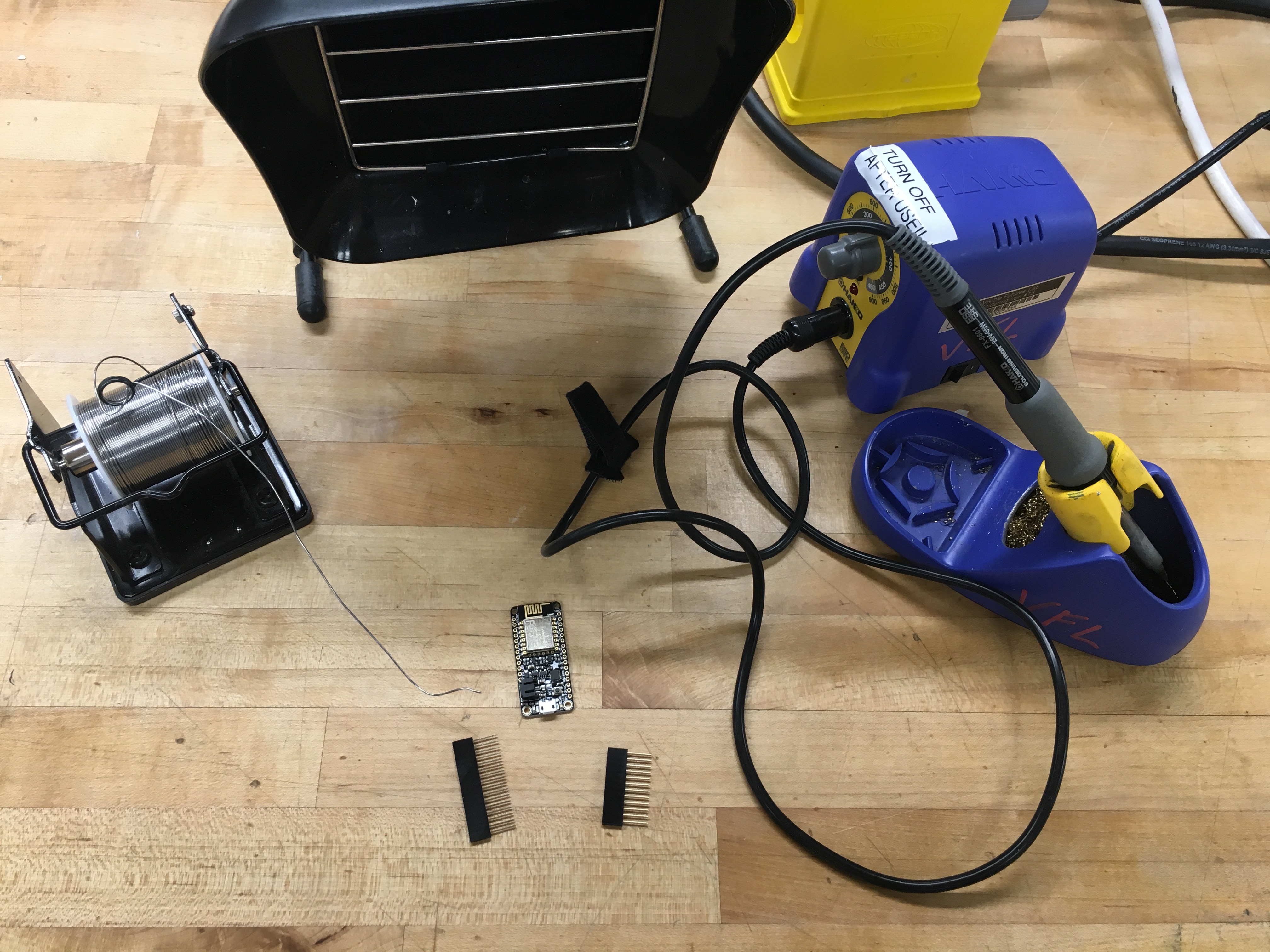
Lets get our boards ready for wiring.
For my setup, a few initial soldering steps were required to get things going with the male feed wires because these were brand new boards.
Wifi Huzzah Board:
- Solder header pins onto the board so can accept male wires
Sound board and amp:
- Solder pins onto both the amp and soundboard so can mount onto a breadboard
- Connect speaker to circuit
- Strip 2 wires
- Solder 1 end of the wires onto the speaker
- Screw down other end of wires into amp board
Setup Huzzah Board
Follow below tutorial links to setup your wifi board:
- Review Adafruit Huzzah Board setup
- Setup IO account
- Add IO Package to Arduino
- Add Boards to Arduino:
- Add link in Preferences of Arduino program:
- Arduino > Preferences > Additional Boards Manager URL: add below link
- http://arduino.esp8266.com/versions/2.3.0/package_...
Below was my primary resource to setup board, library, and accounts:
Setup Audio Board
Now lets setup the audio board to play sound when triggered.
I used a recording of my voice saying "Heads up", so I'll walk through my process
- Open quicktime, select File < New Audio Recording
- Record your audio clip
- Convert the audio clip to a .WAV
- I used this webiste: http://www.zamzar.com/convert/mp4-to-wav/
- Change the name of the audio file to "T03.WAV"
- Note - the file is name T03 because we are using pin3 on the audio board.
- Upload the file onto the board:
- Plug board into computer
- Drag T03.WAV file into the board folder
- Test that the file plays!
Primary resource:
Setup IO Feeds and Dashboard
- Login to your IO account
- Create a feed called msg
- Create a dashboard called messages with an on/off switch
Primary resource:
Setup IFTTT Adafruit Connection
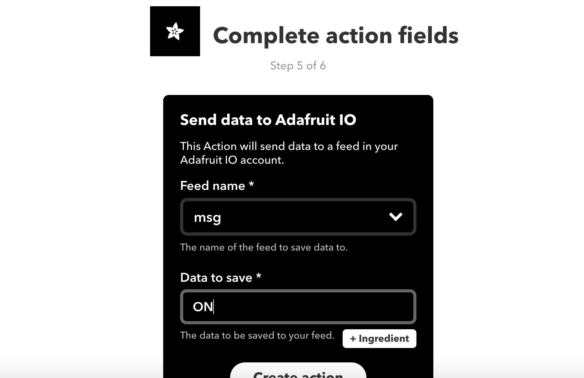

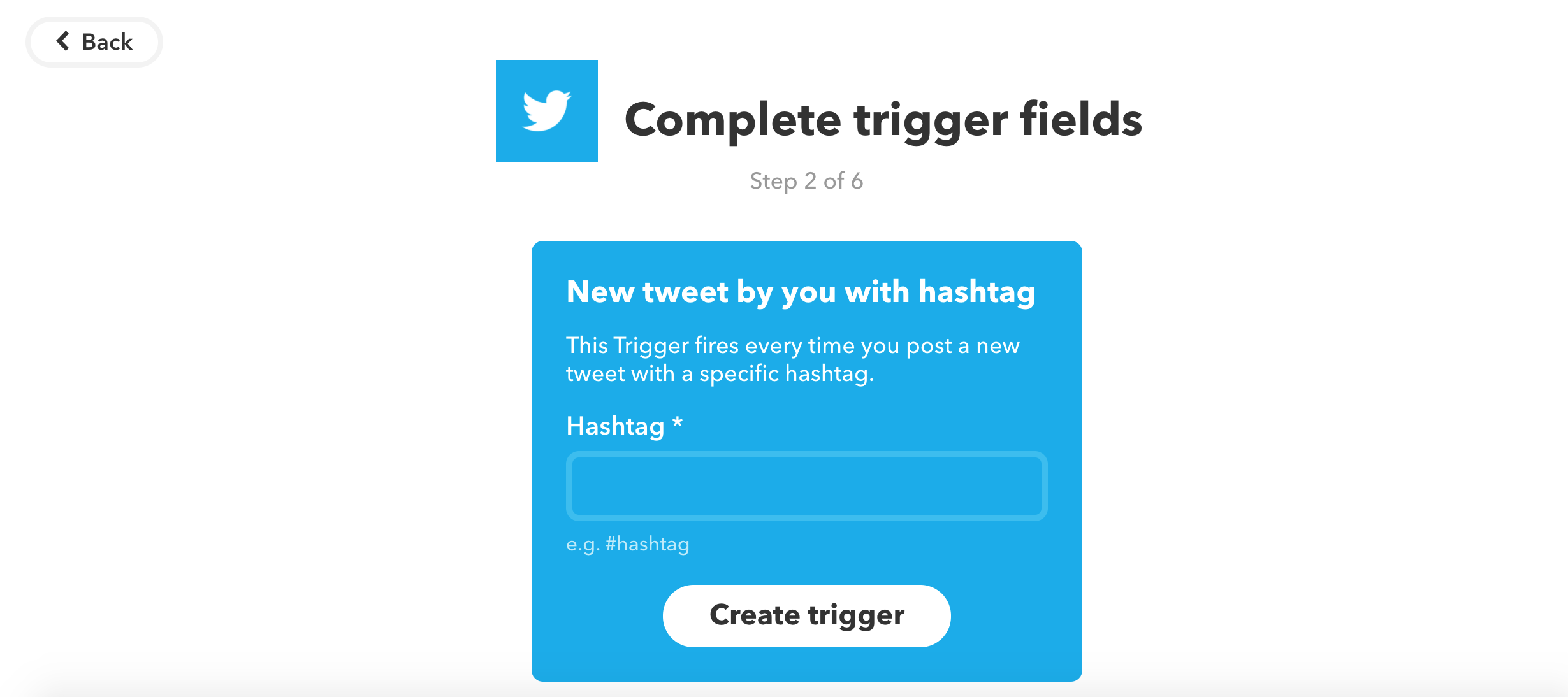
Send "ON" to the arduino wifi board through a trigger on IFTTT
- Create IFTTT account
- Select 'create new applet'
- Select '+' sign
- Select Twitter
- Select "New Tweet by You with a Hashtag"
- Fill in the hashtag you'd like to use for arduino triggers (mine is #headsupPOD)
- Select '+ that'
- Search for 'Adafruit'
- Select 'Send data to Adafruit IO'
- Select 'msg' feed and write "ON" as data to save
- Note - capitalize "ON" as that is how the arduino code reads the incoming characters
- Finish!
Side note - the message that is sent to the feed in this step is customizable. We can setup multiple triggers with different "Data to save" which the arduino code can read and react to. In the code I have provided, we trigger action when "ON" is sent to the feed.
Setup Full Circuit
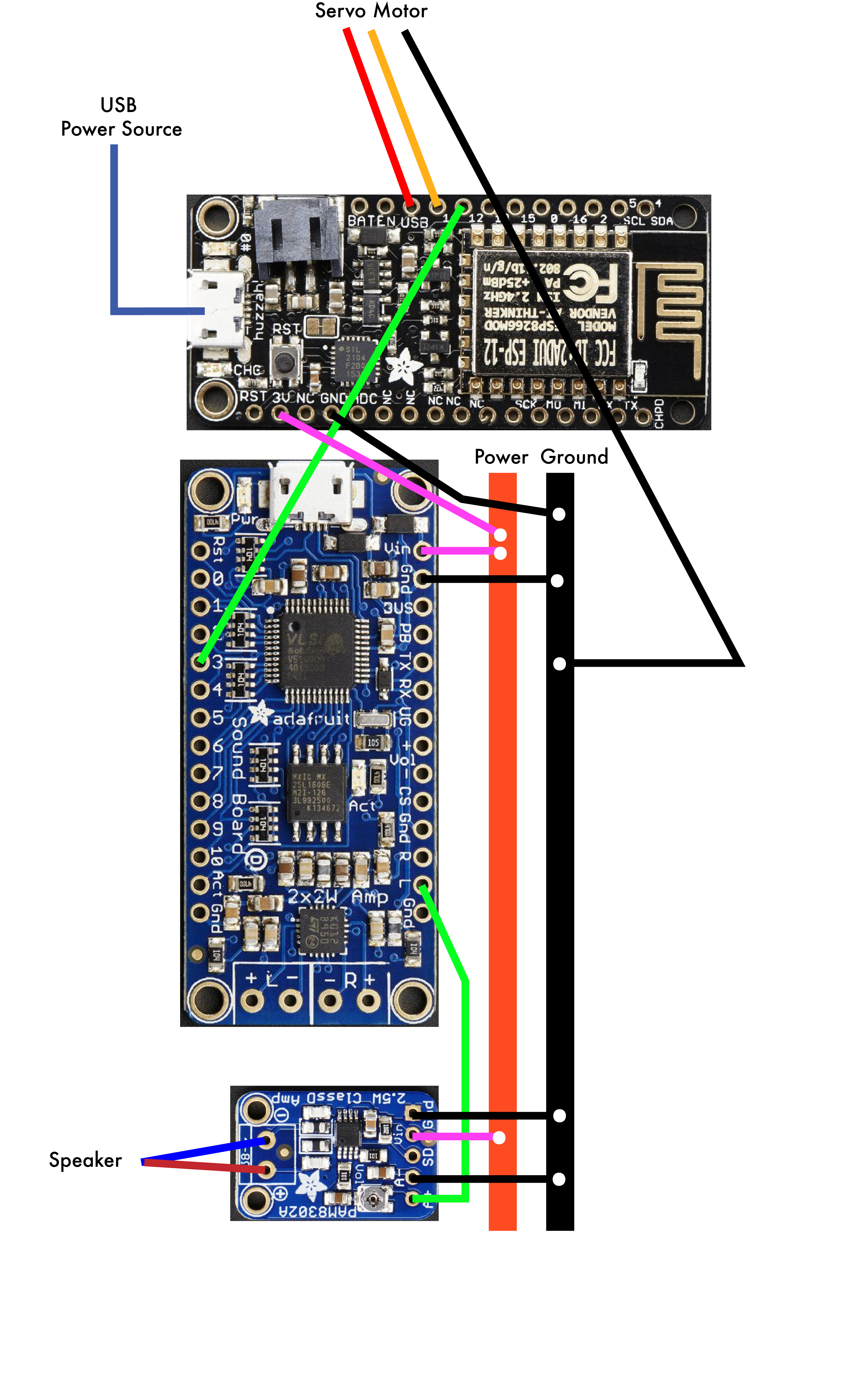
Construct your circuit using the image and diagram illustrated. This initial setup will be used to prototype and confirm all connections work with the code.
Note - in my case, I was able to fit everything into the final enclosure in this layout. It would be possible to shrink some of this wiring down if required, but my box was large enough to fit everything.
Test Code

Download the sketch code provided.
- Edit the Wifi credentials & change to your AIO key
- Compile and upload sketch to test
- Note - make sure port is correct
- Tools > Port > SLAB_USBtoUART
- Note - make sure port is correct
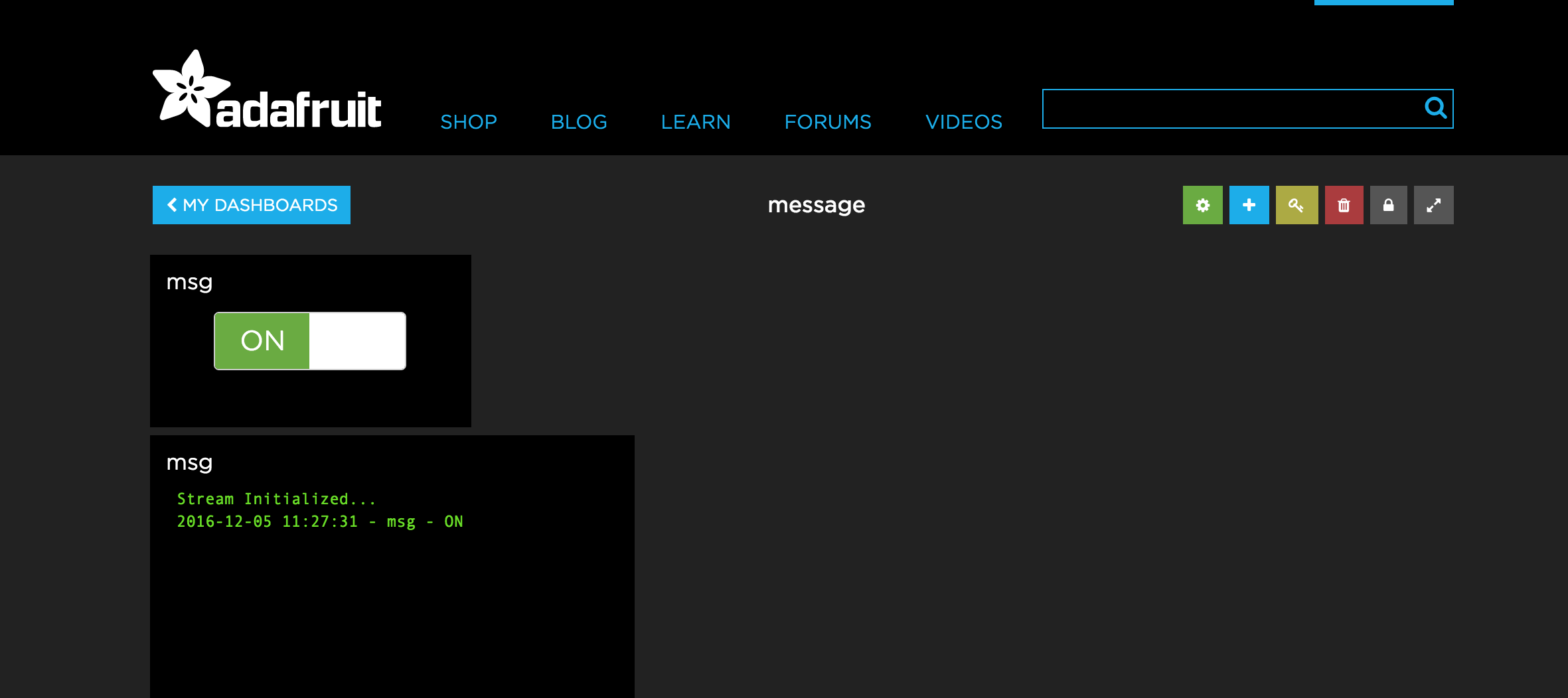
- View the status of Adafruit data on the 'message' dashboard
- Test the wifi connection by toggling the button on/off to confirm reacting
- Note - the code provided will turn the on-board light on/off as this button is toggled
- Suggestion - if having issues, disconnect speaker and servo from the circuit and first confirm the light toggles on/off, then add on the components accordingly. Feel free to comment out code for the servo and audio board until the wifi connection is working.
- Test the Twitter functionality by sending a tweet with the determined hashtag
- Note - both the light and the dashboard should toggle with the appropriate tweet
Downloads
Fix Foam Gun + Servo Together
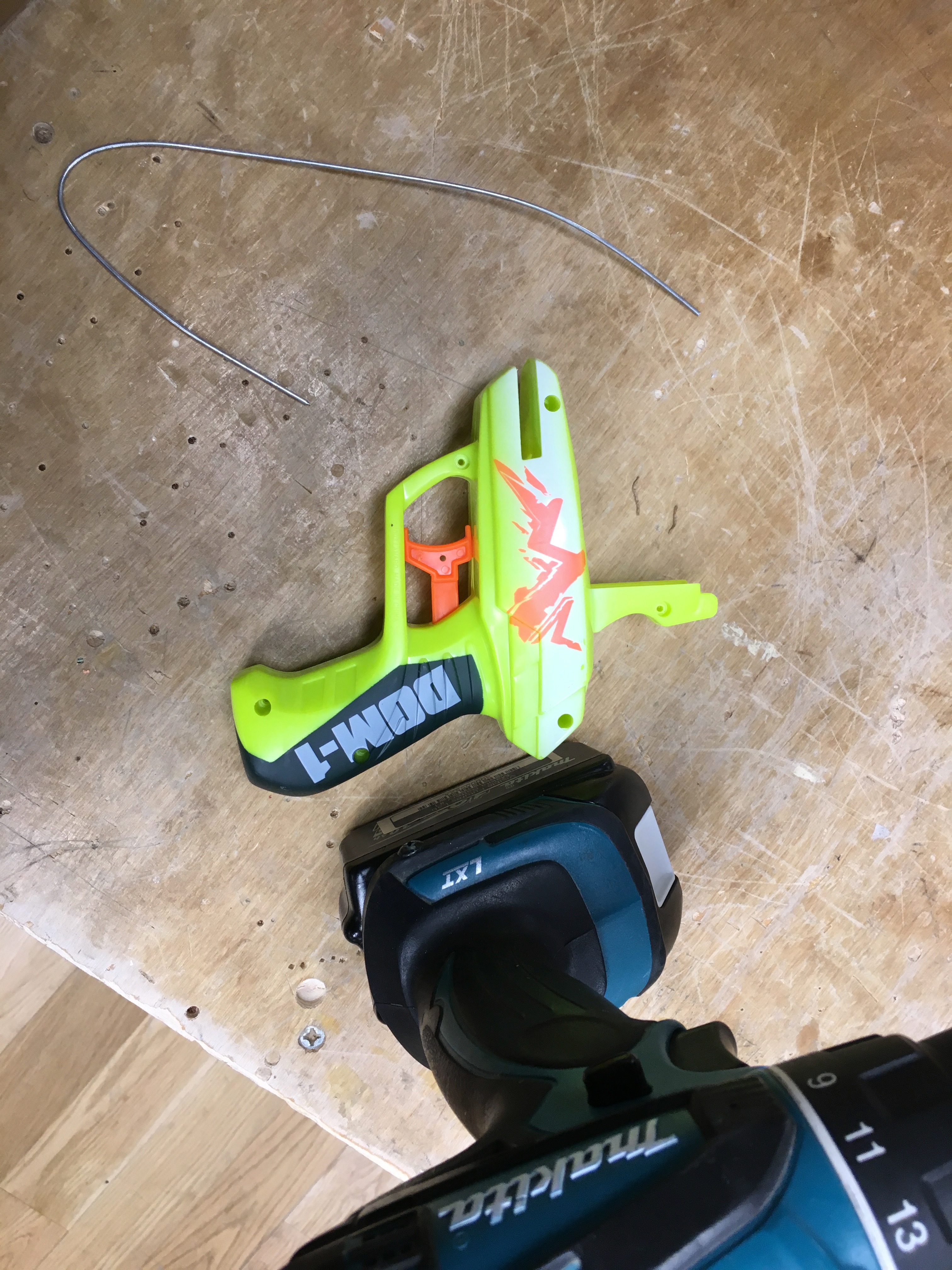
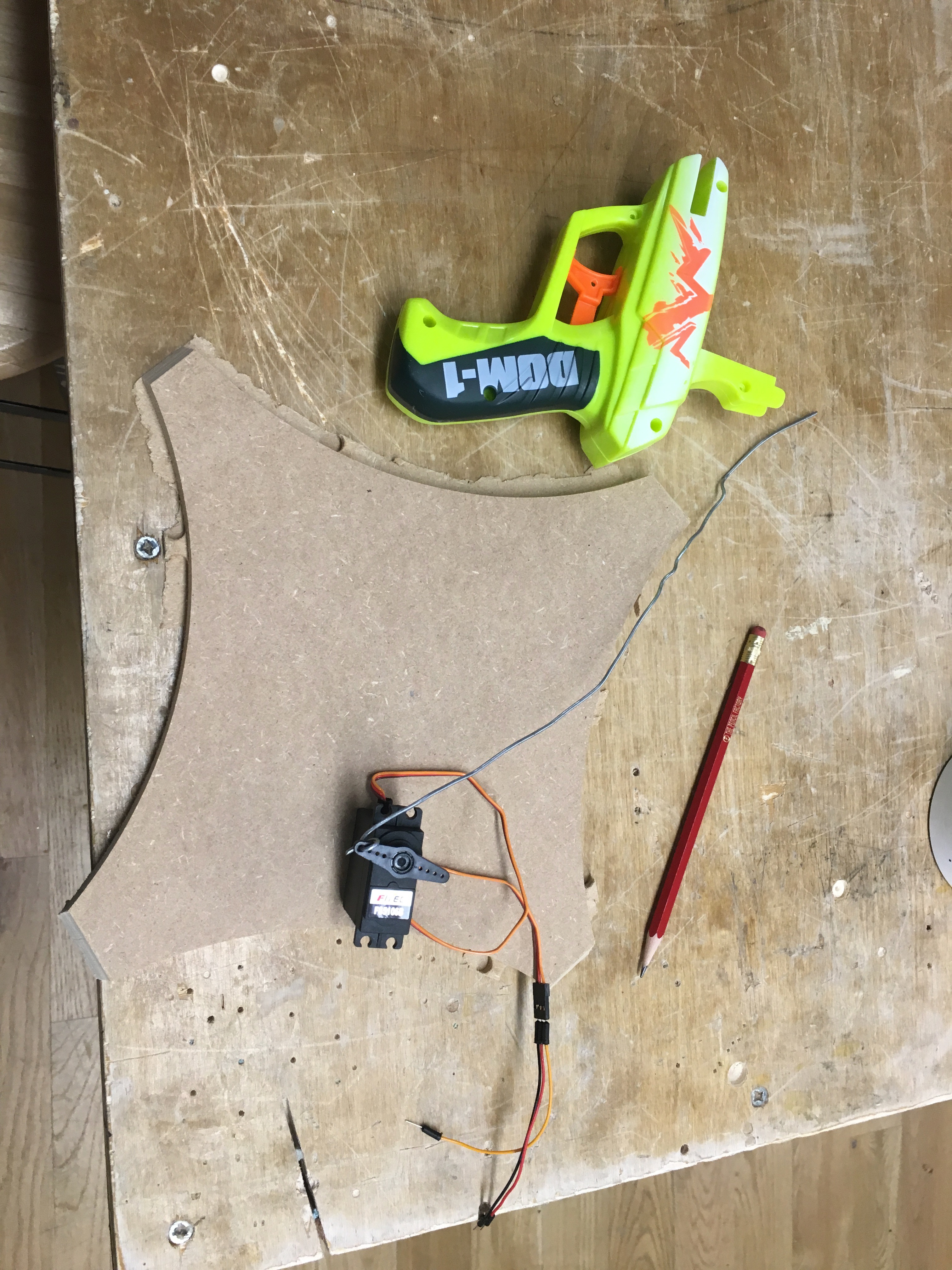
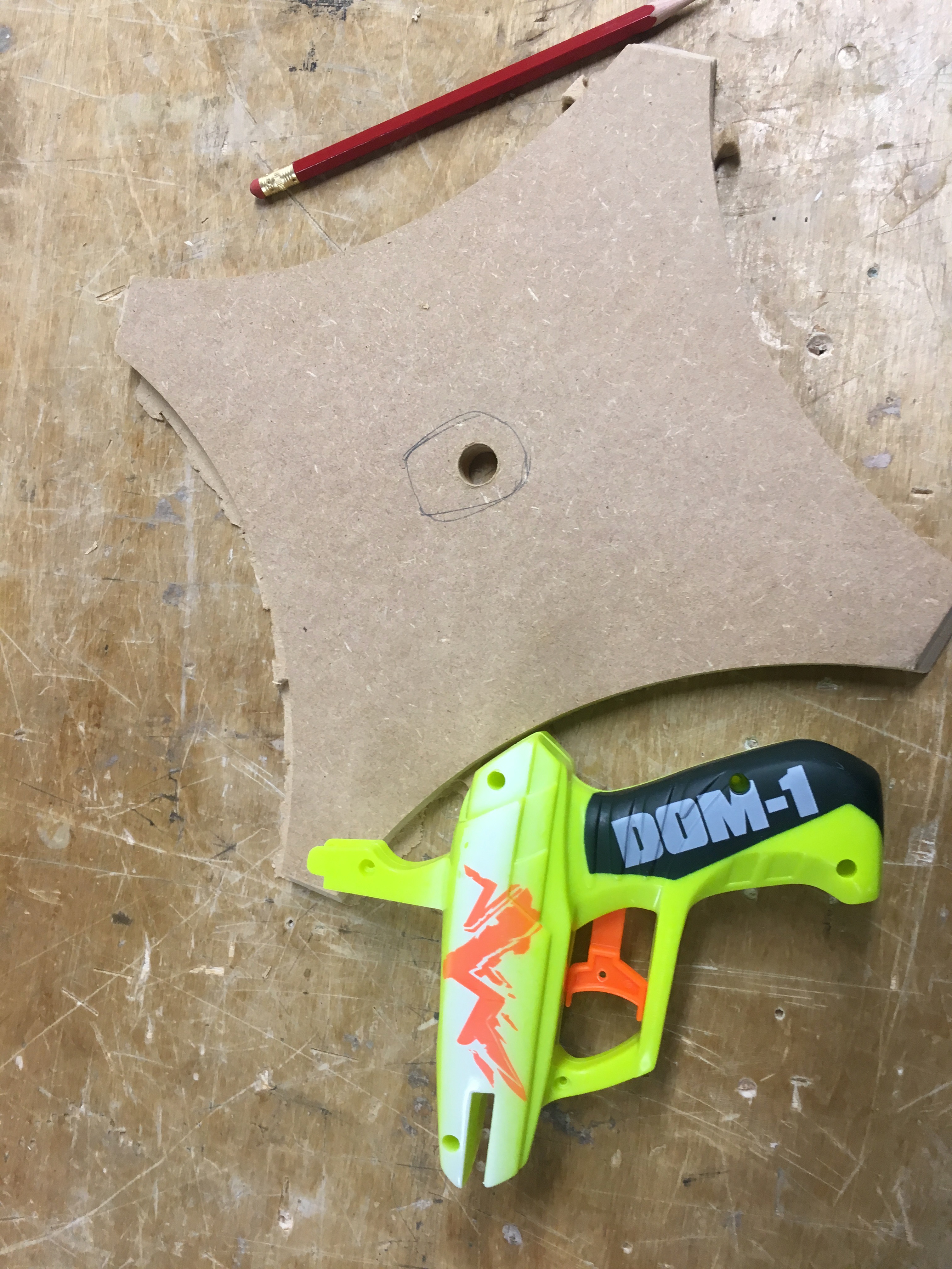
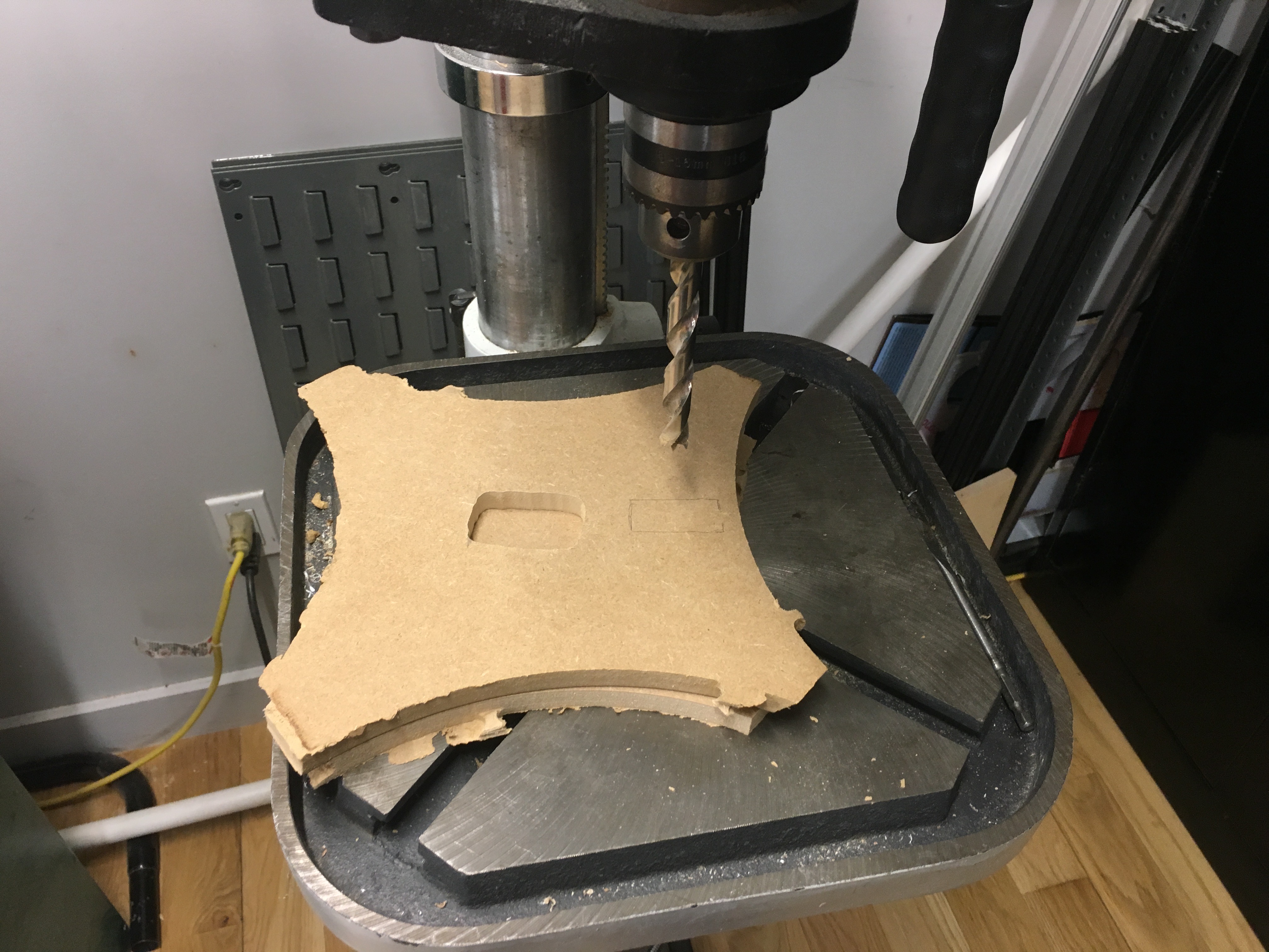
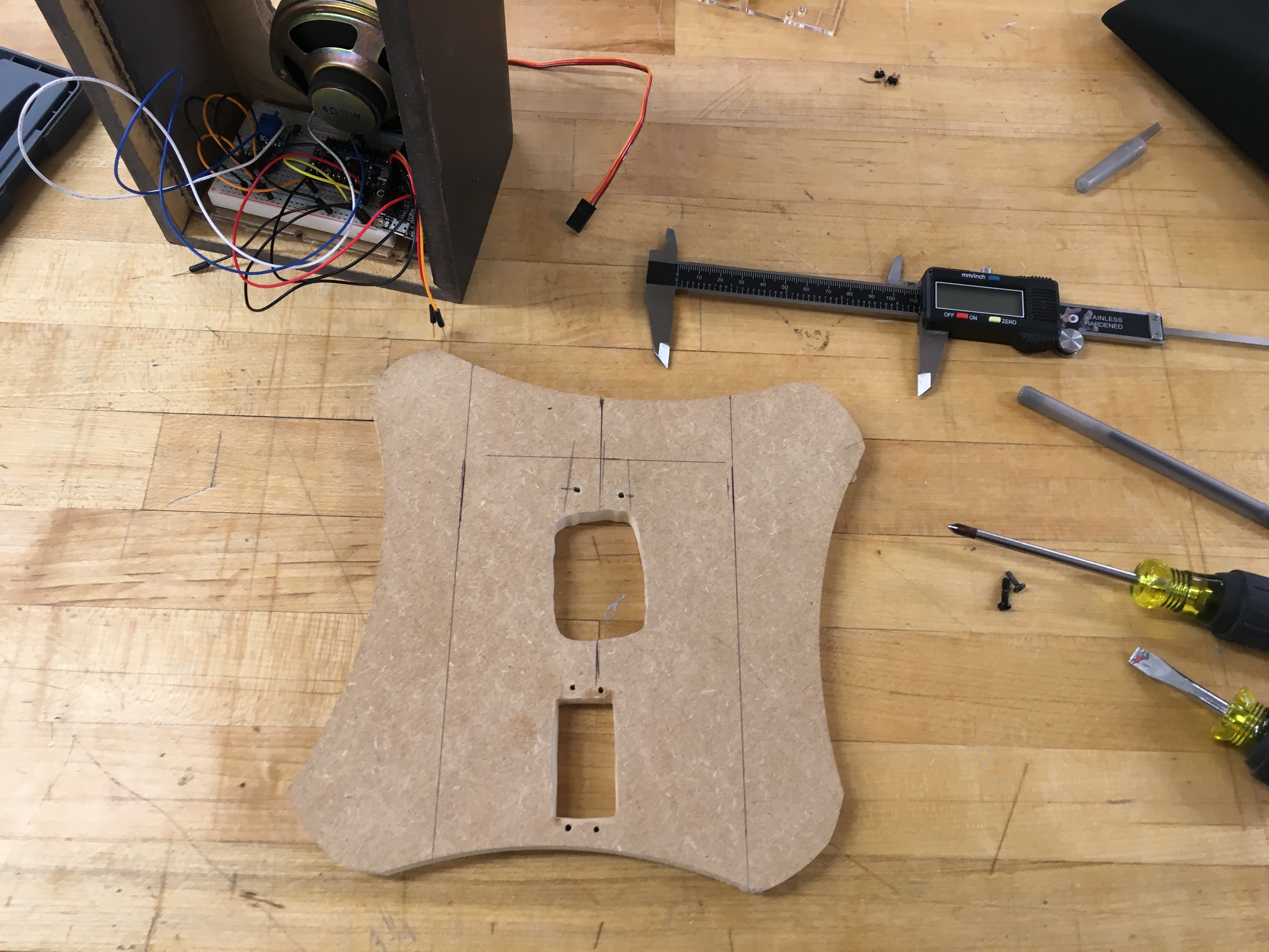
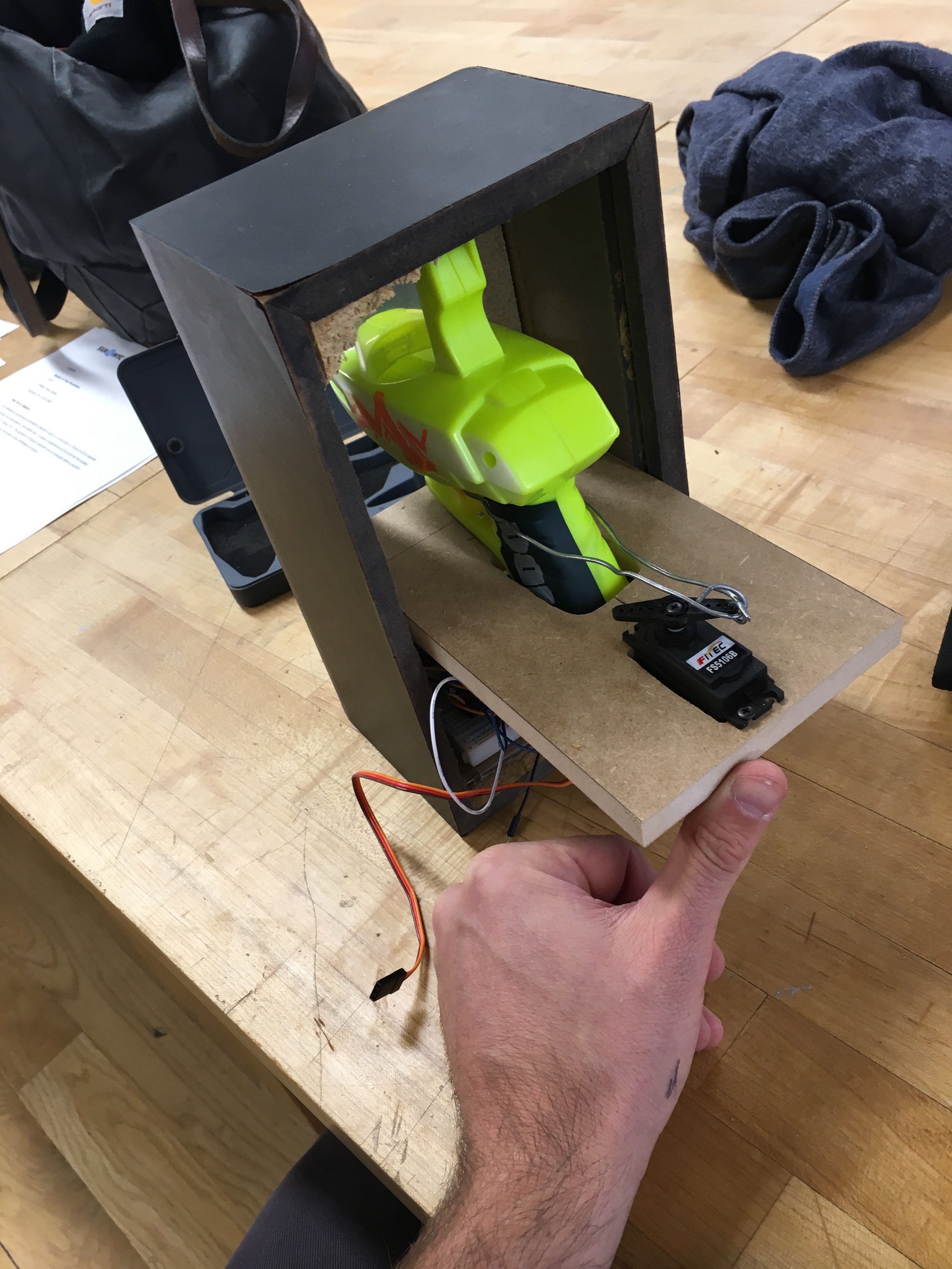
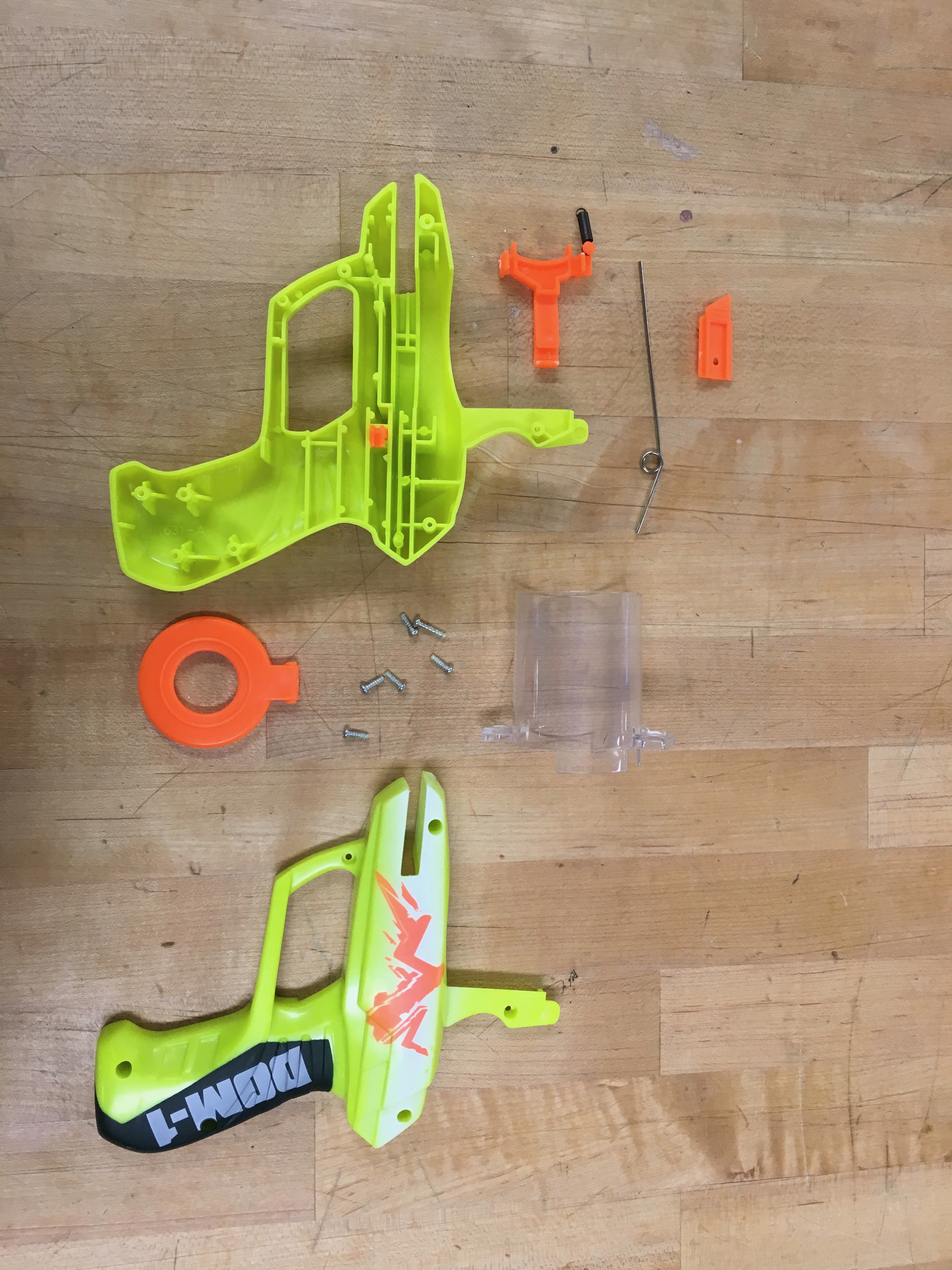
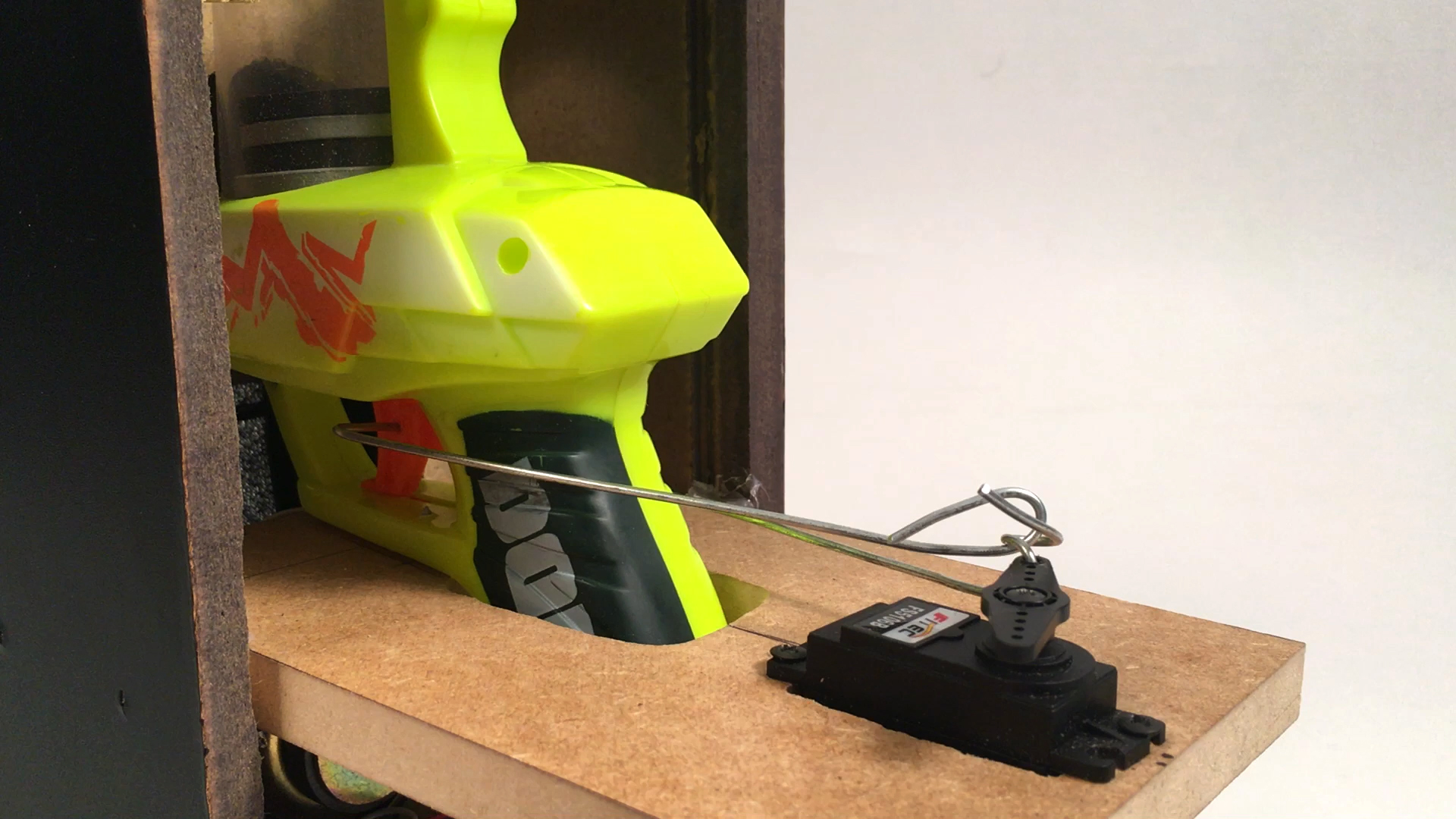
In this step we will build a platform to mount the foam disc gun and the servo together to pull the trigger when the servo motor is activated.
- Drill hole in trigger of gun (pic attached)
- Drill hole in servo arm to enlarge to fit metal wire
- Find/buy piece of wood to use for platform
- Note - I found a piece of scrap MDF board in the shop, which is why the odd, oblong shape.
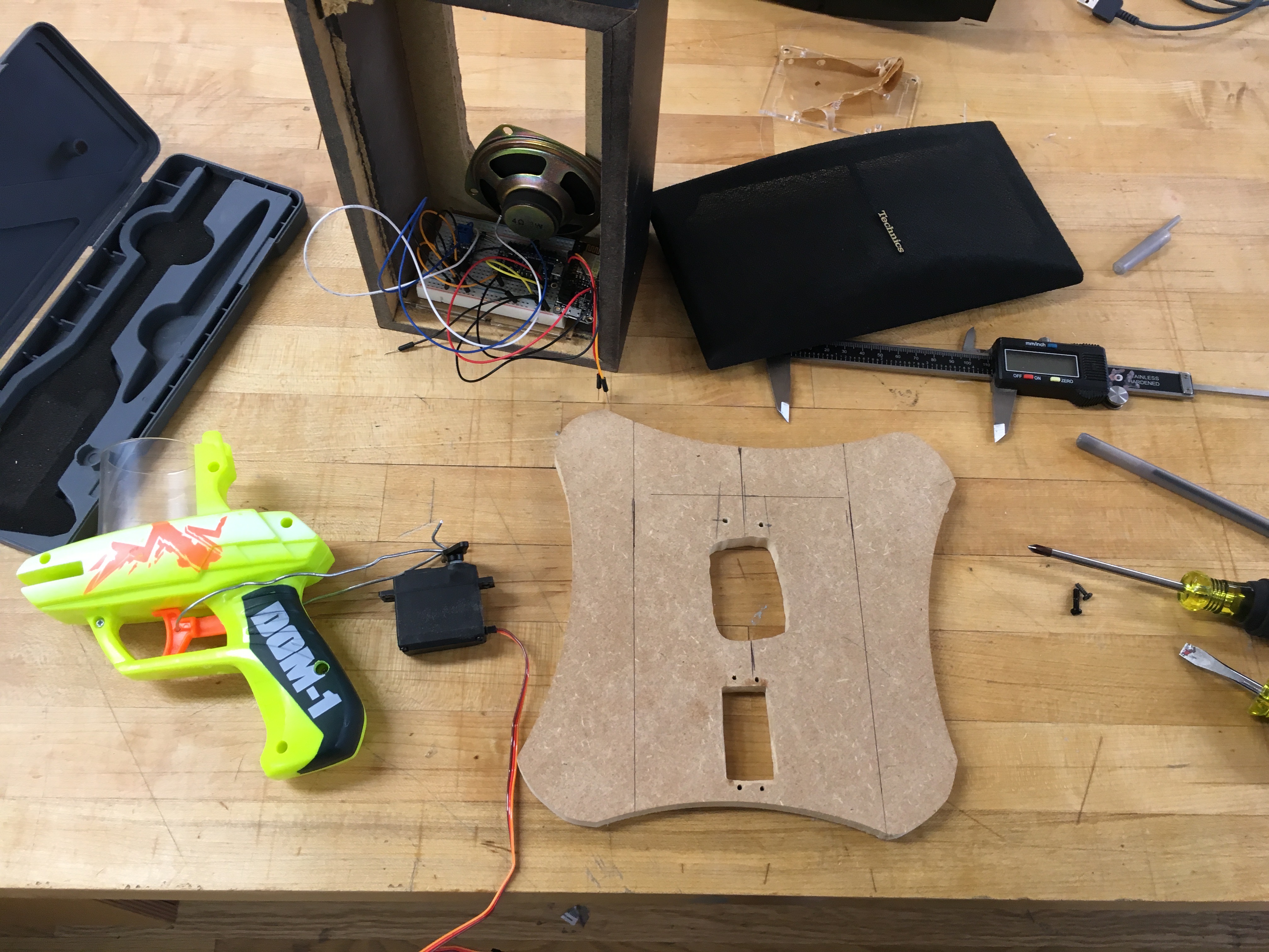
- Map out region for foam disc gun and servo to sit into
- Map out a distance of the servo from the trigger by at least 3 inches.
- Cut and widen the openings to fit the gun and servo into
- Drill large hole at center
- Sand and/or file to outline
- Drill mounting holes for the servo
- Drill mounting holes for the foam disc gun
- Note - this was particularly tricky because you need to drill from underneath the gun
- Suggestion = drill holes into the gun first, then map out where to drill pilot holes on the board
- Mount both gun and servo onto the board with screws
- Note - mount the servo motor such that the resting location from arduino code is where you want it to be and that it is rotating in the right direction to pull the trigger
- Also - don't forget to pop off the top piece cap of the loading magazine (orange cap in pic attached). You will need to have access to the magazine chamber once mounted in the box.
- Line the metal wire through the trigger of the gun
- Bend metal wire around gun and into the servo opening, without dramatically rotating the servo motor
- See pic attached of my final wiring
- Plug in and test it out!!
NOTE - to get the servo to pull the trigger took LOTS of trial and error: multiple wires and repositioning. Be careful not to torque the motor too much and strip the internal gears (I did this!). Best tip is to run the servo without it connected to the gun to be certain that the direction and rotation is right and can see how far need to rotate- then place the metal wire into the servo from the gun trigger.
Hack Into a Speaker Enclosure
First, fit the guts into the box:
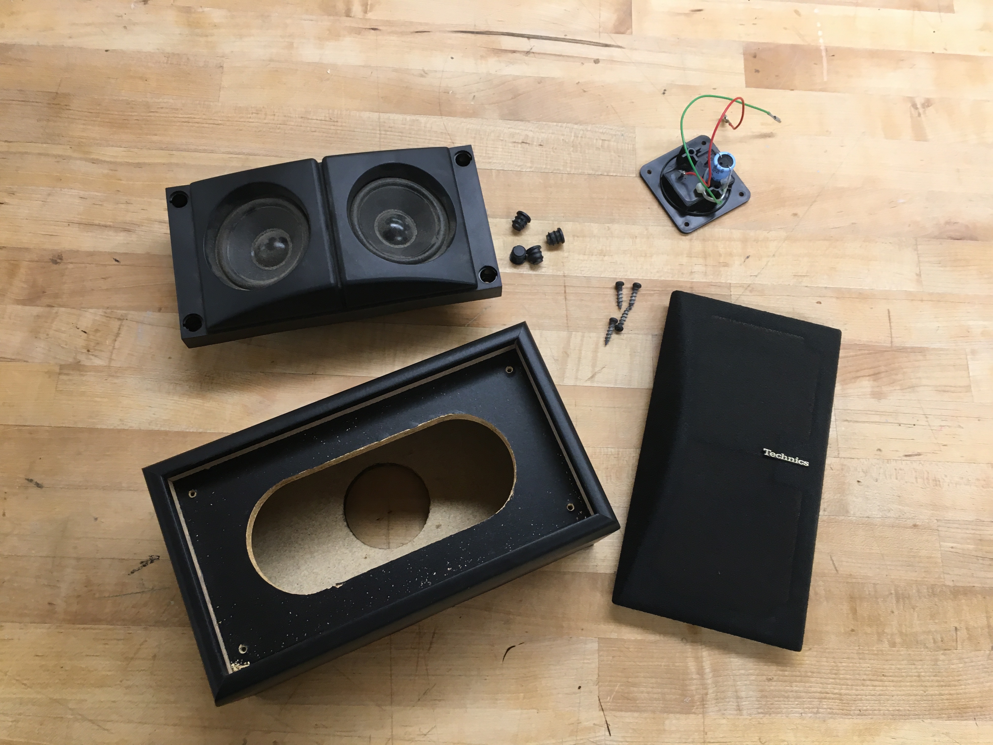
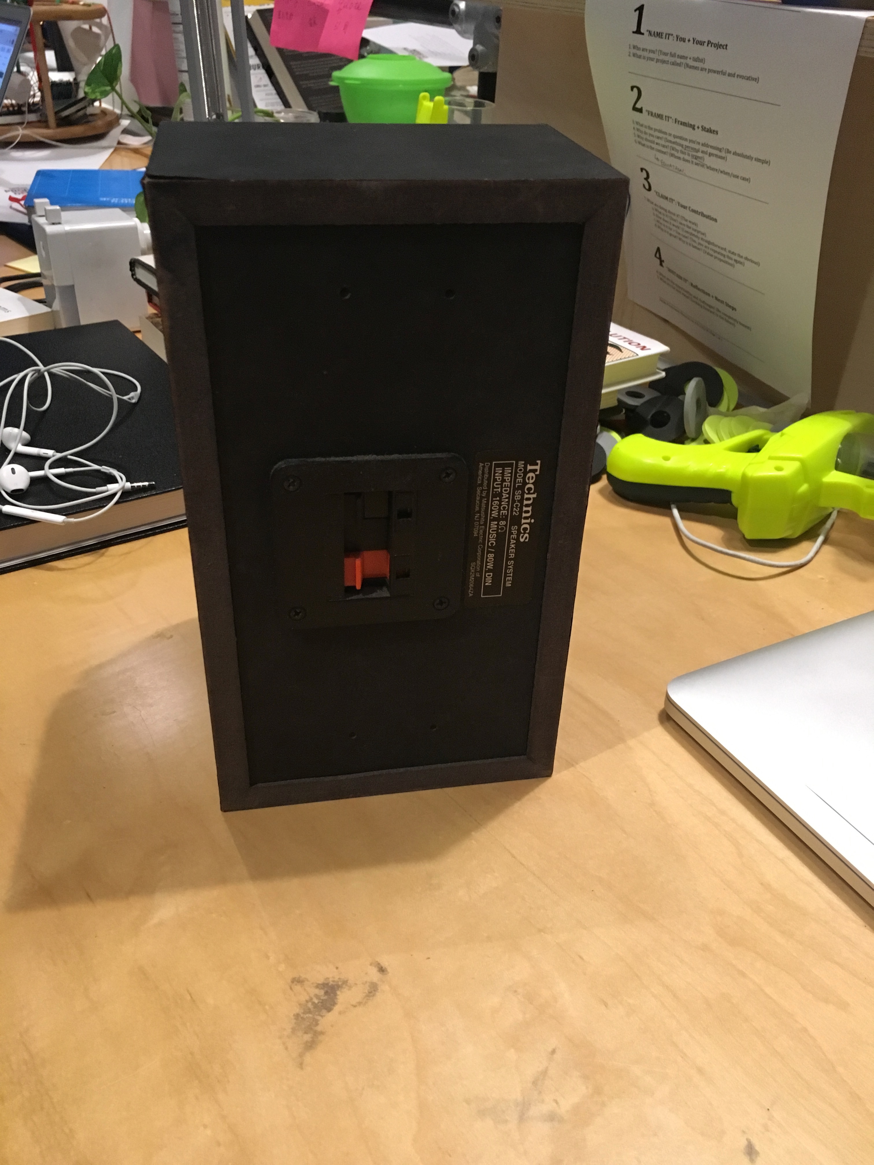
- Disassemble speaker box
- Note - backside on my box was glued shut, so I had to saw + hammer it out (sorry didn't take pics of this)
- Map out and drill pilot holes for mounting our standalone speaker into the box
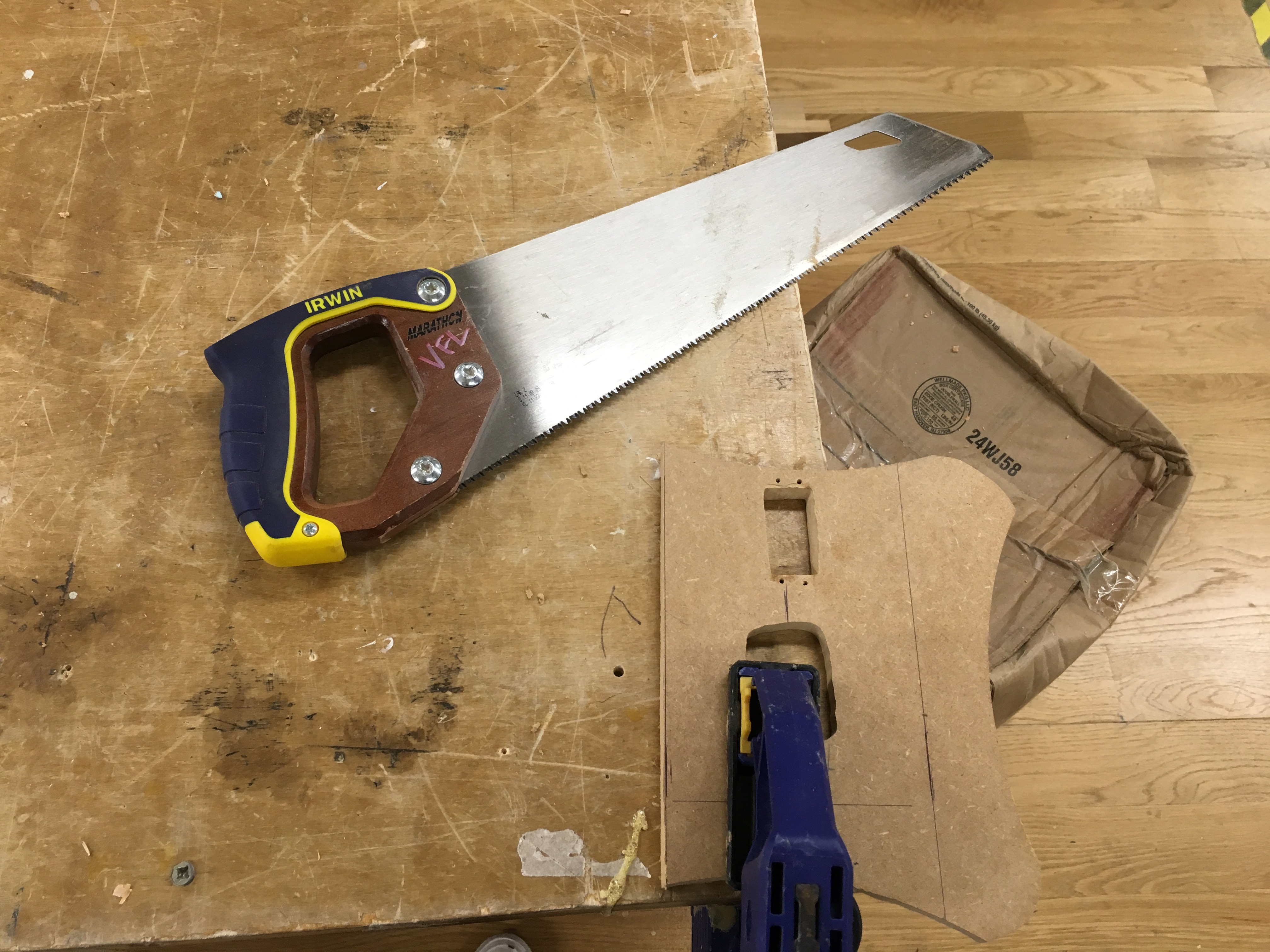
- Measure width of speaker box to determine width of gun + servo platform
- Saw platform to width
- Establish height and location of platform in box to determine top down loading hole
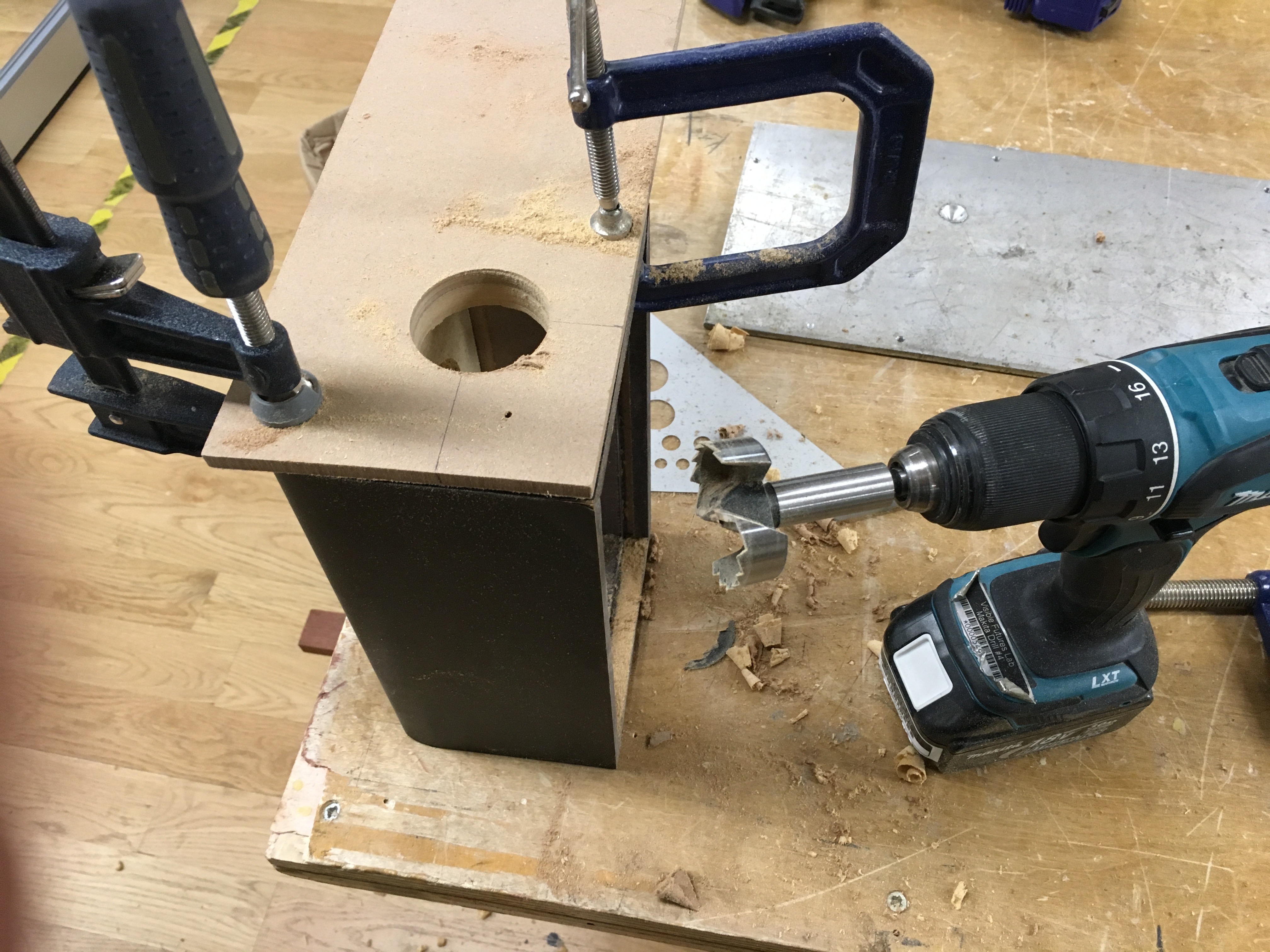
- Using the Forstner drill bit, drill a slightly oversized hole in the top for loading disc bullets
- Note - the extra piece of wood between cutting bit and work piece is to create a nicer edge finish on the top
- Screw speaker into place
- Tack down electronics boards into place: double sided tape or hot glue, depending on preference
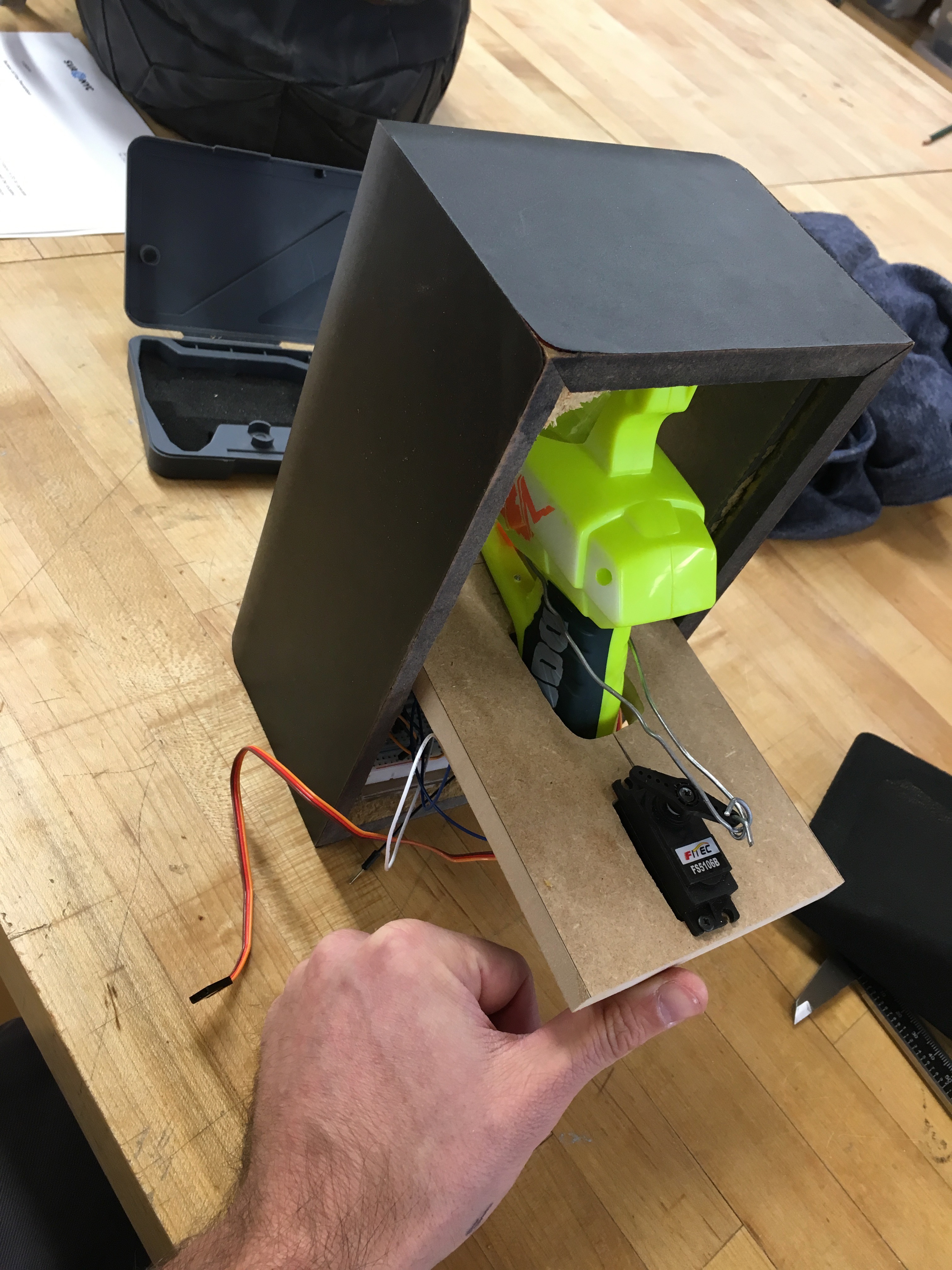
- Fix gun + servo platform in place with hot glue for temporary hold
- Note - ensure the loading chamber and the opening hole are aligned in this step
- Using pneumatic nail gun, fix the platform in place permanently
Next, cover the box to hide everything:
- Determine the location of the foam disc shooter and the cover screen: mark with sharpie
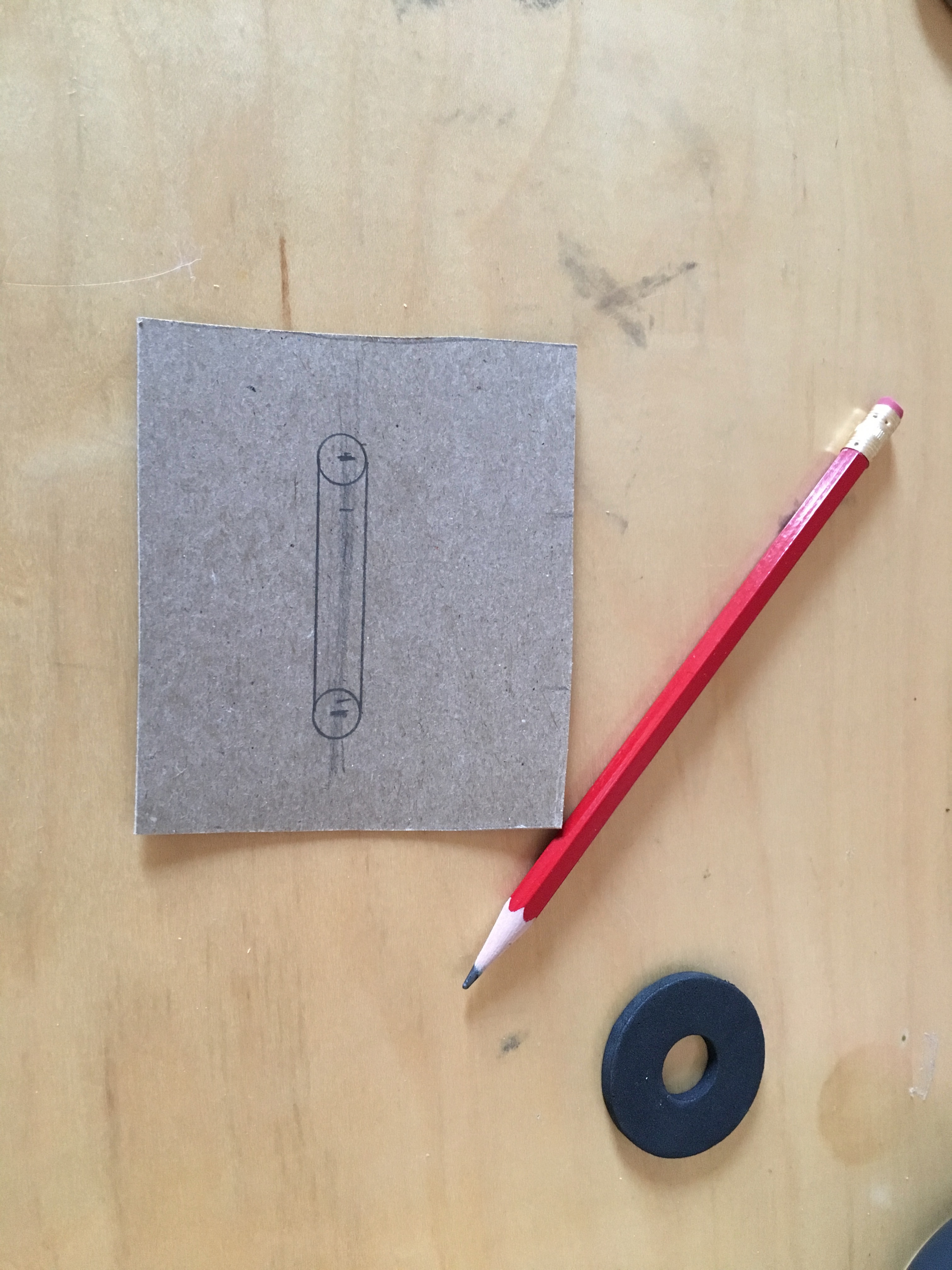
- Cut out a piece of cardboard to mount on the backside of the cover screen
- After identifying location on cardboard, draw out a slot for cutting
- Cut the slot using an X-acto knife
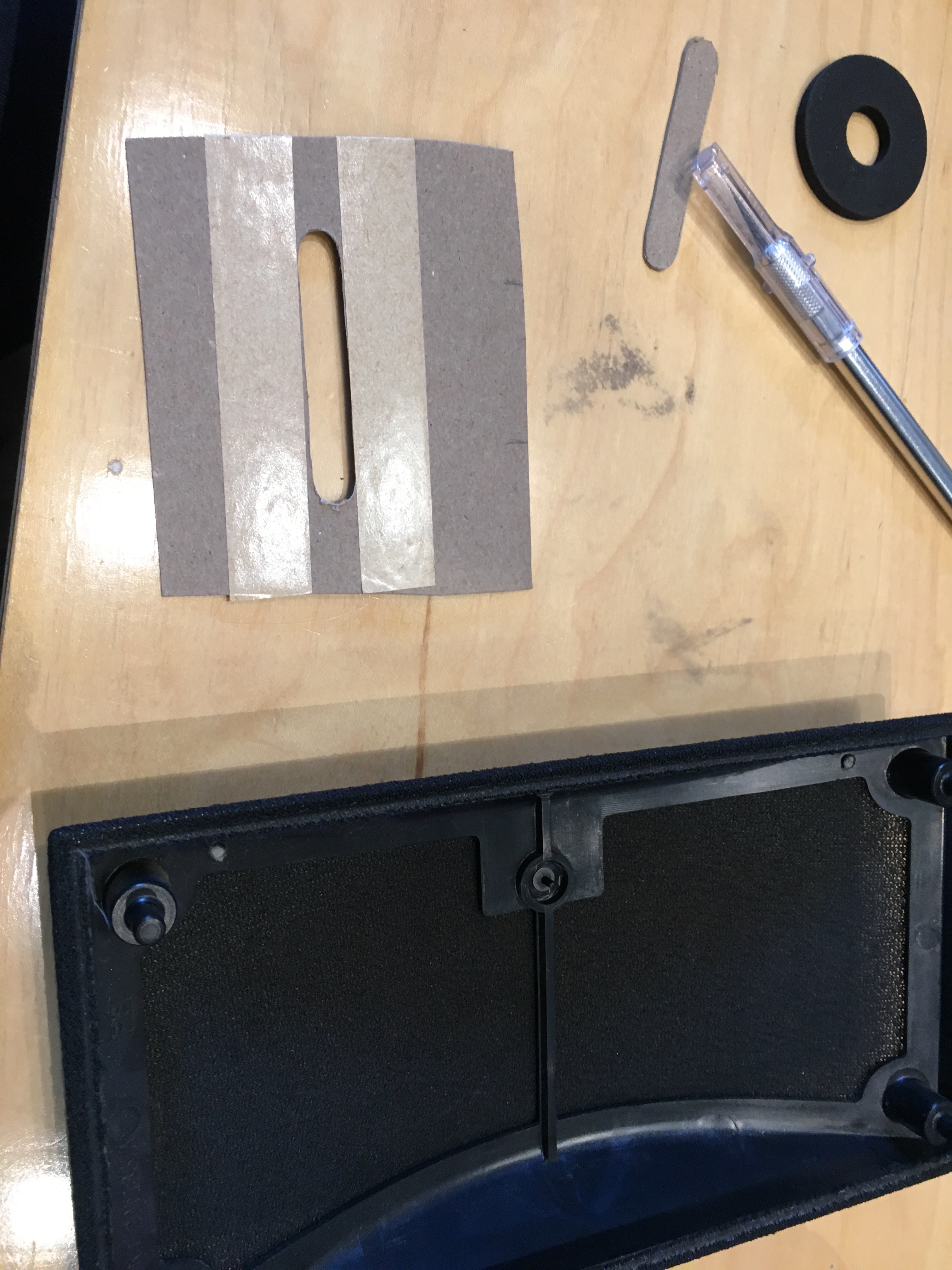
- With double sided tape, mount the cardboard on the back of the screen + outside plastic enclosure
- Note - you want the double sided tape to contact the screen so when we cut the screen in the middle it stays in place
- Place double sided tape on the backside of the cardboard
- Slit the screen down the middle of the cardboard slot
- Fold the screen onto the double sided tape to create a clean opening
- Using double sided tape, fix the entire screen back component on the box at the top
- Note - do not permanently fix the screen on the box without testing that the discs fly through!
- I fixed it only on the top so I can still open it up in case discs don't fly through
- Test it out!!
Start Firing!!
Place your "Heads up" in interesting places and see what happens.
Please share your stories if you go forward with this project!
Thanks for reading!! Hope you enjoyed it!