Handheld Weather Station
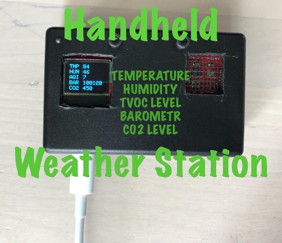
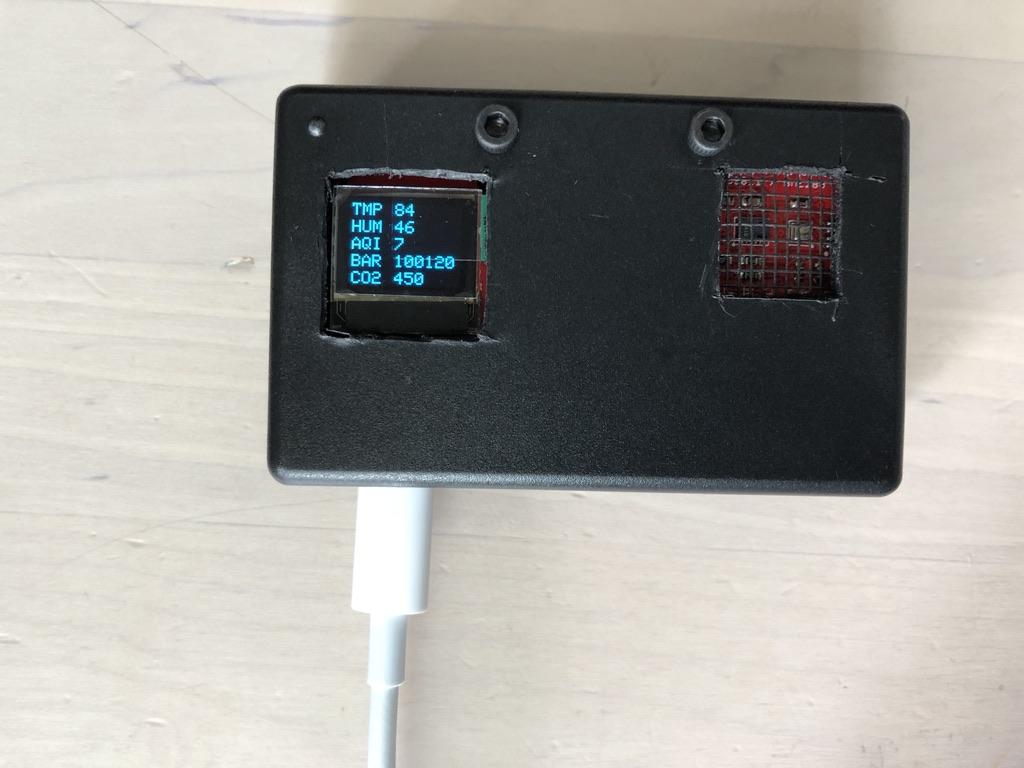
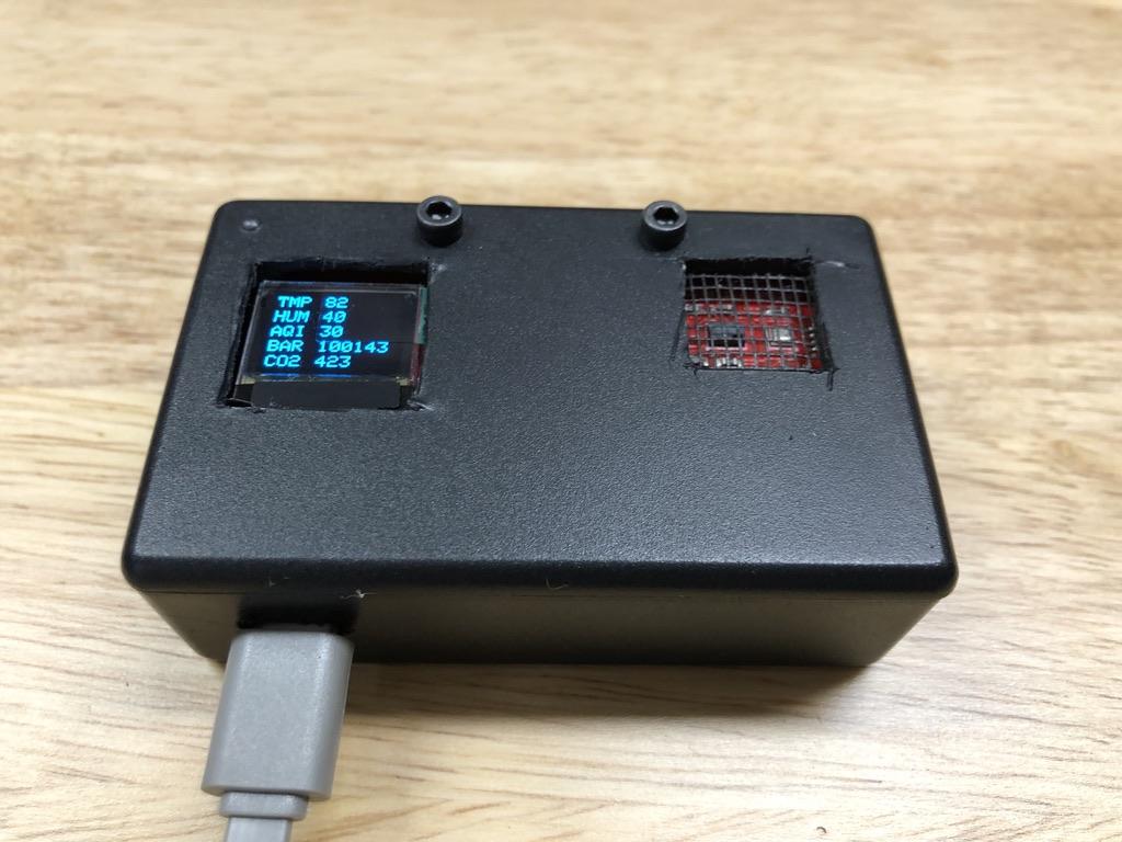
In this Instructable we will be using an Arduino, an oled display, and a SparkFun environmental sensor combo with CCS811 and BME280 sensors on board to build a handheld device that measures temperature, humidity, TVOC levels, barometric pressure, and carbon dioxide levels. You can use any Arduino with the provided code, but I am using a SparkFun Qwiic pro micro. If you are a beginner, I suggest you use the same parts I am using, just to keep things simple. I chose the SparkFun Qwiic pro micro board for its small size and the Qwiic connector, making it easy to connect your components. If you are using a different board, make sure to buy a Qwiic hat, phat, or shield to fit your board. https://www.sparkfun.com/phats.
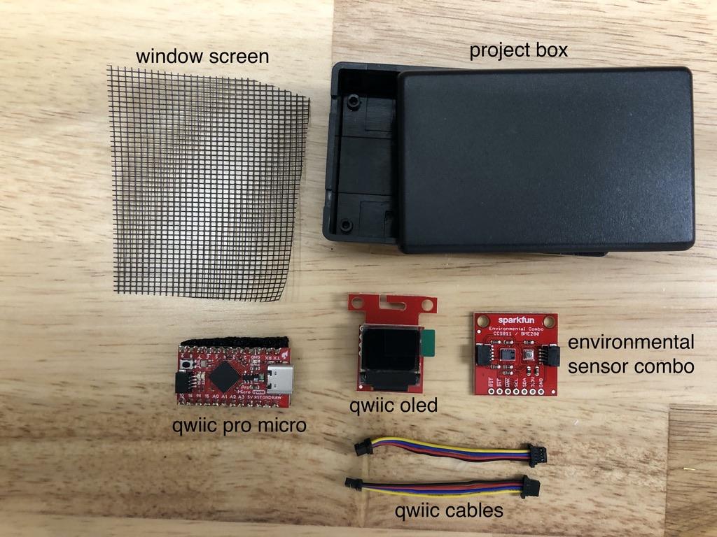
Supplies:
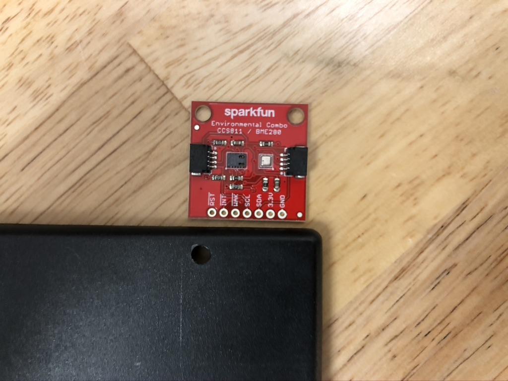
- SparkFun Environmental Combo Breakout - https://www.sparkfun.com/products/14348
- SparkFun Micro OLED Breakout - https://www.sparkfun.com/products/14532
- SparkFun Qwiic Pro Micro - https://www.sparkfun.com/products/15795
- Qwiic Cable, 50mm - https://www.sparkfun.com/products/14426
- Project box, size to your components, I'm using around 3 x 2 x 1 - https://amzn.to/37mssXd
- Optional: If you are using the Qwiic Pro Micro, you may need a usb-c cable(if you don't already have one) for power and programming
- Window screen, about 1.5 x 1.5 inches
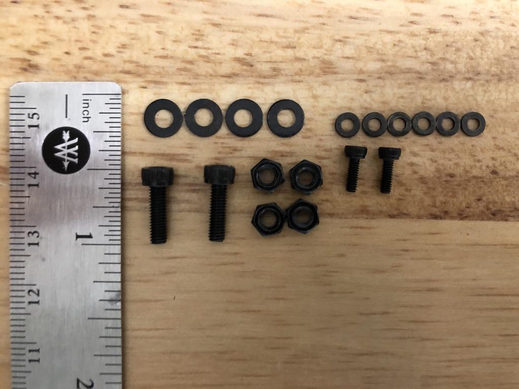
- Screws (see picture above)
Tools:
- Hot glue sticks and hot glue gun
- Scissors
- Razor blade or x-acto knife, capable of cutting through your project box
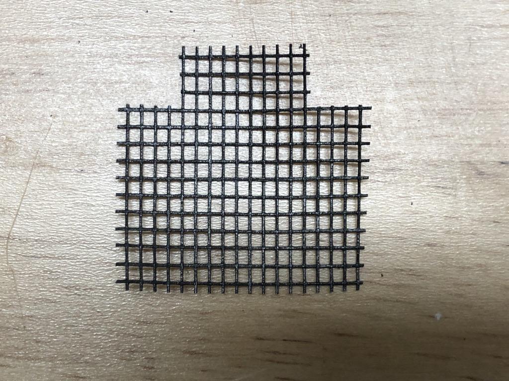
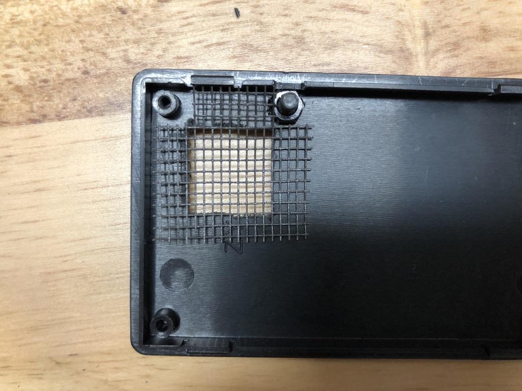
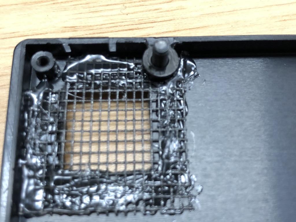
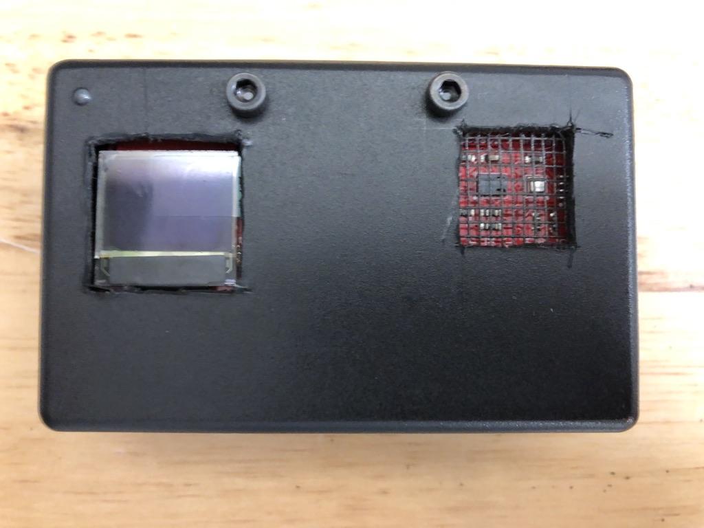
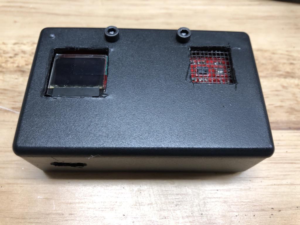
Mark and Cut Holes and Put in Window Screen
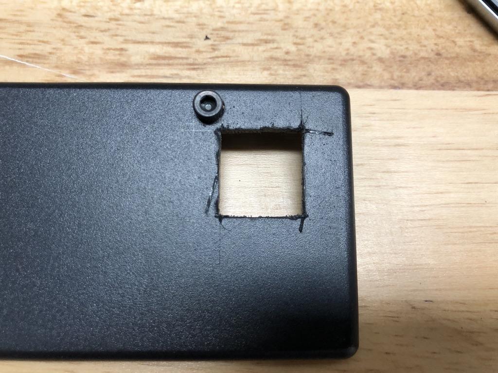
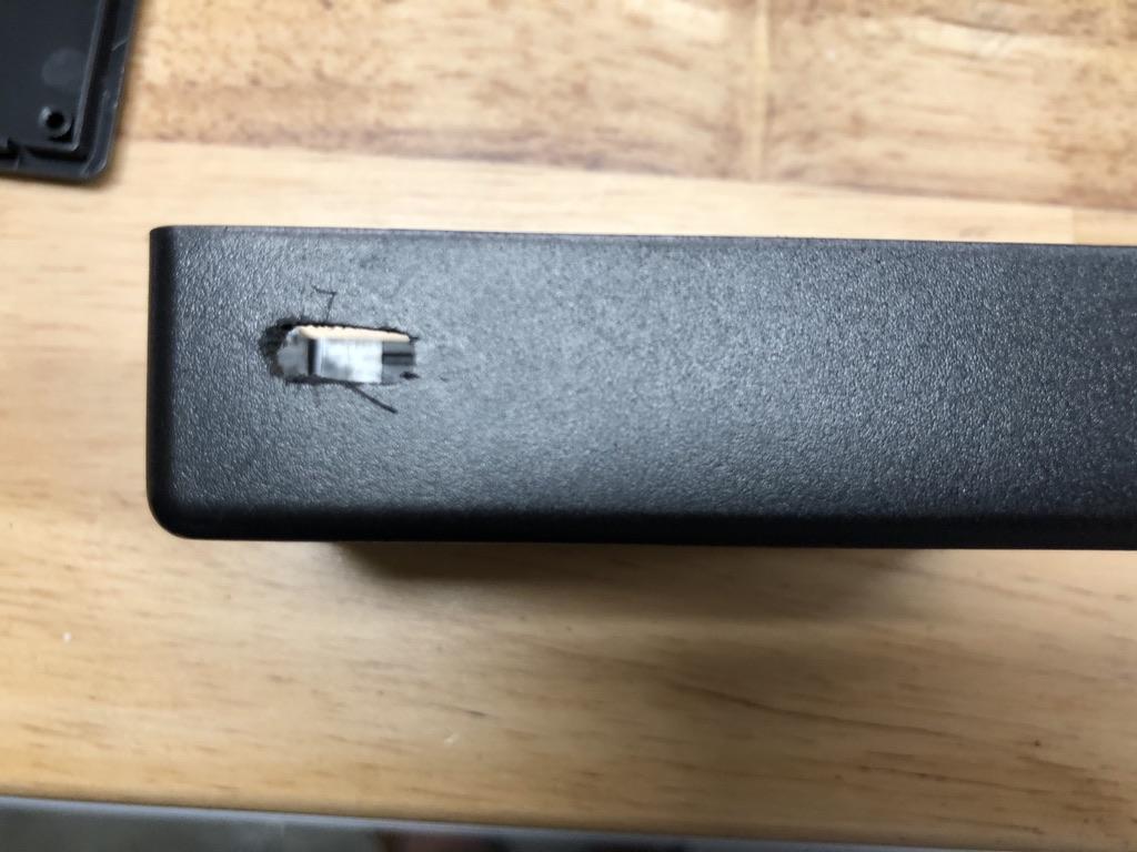
We will mark and cut holes for the oled, environmental sensor and USB-C connector for programming and power.
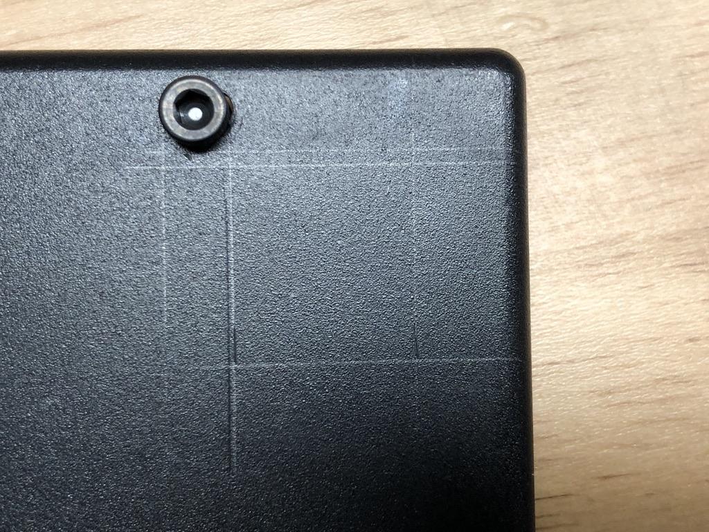
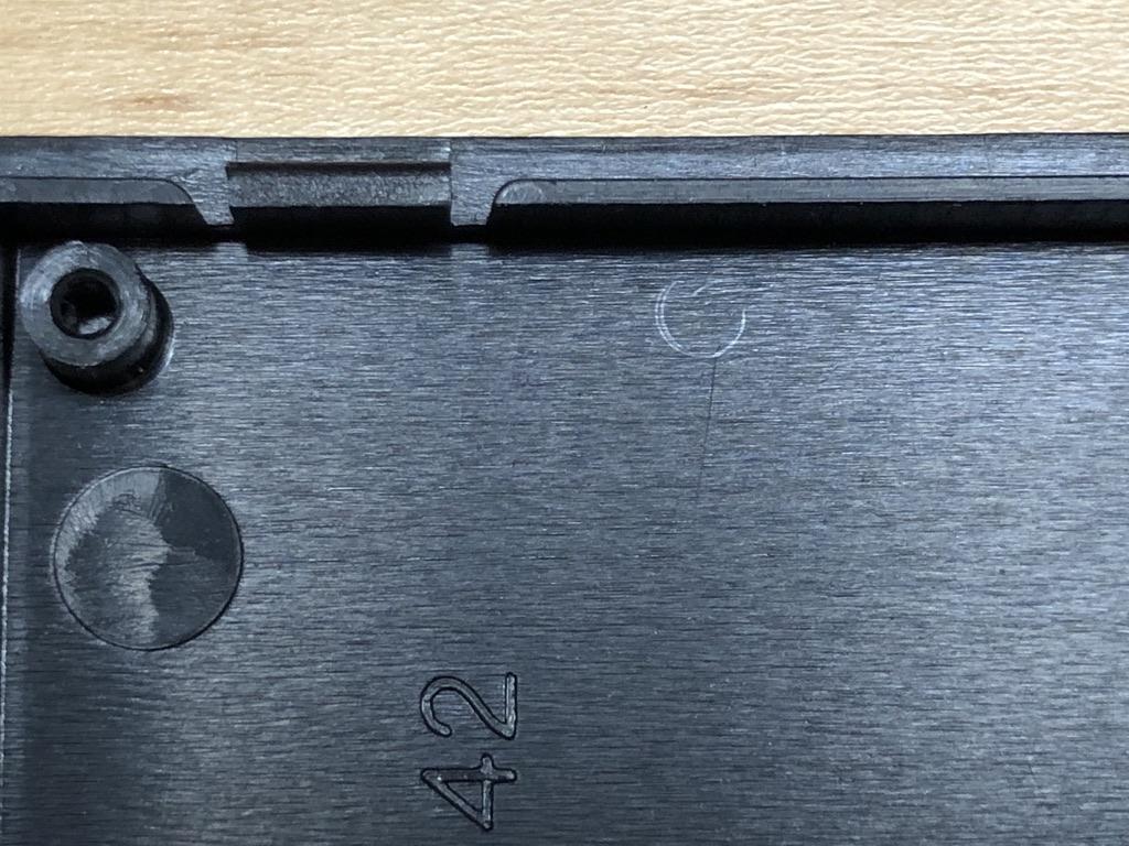
- Line up your components where you want them and mark the screw holes.
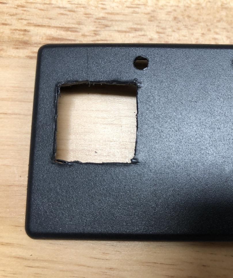
- Mark squares, for the oled, a square the size of the screen and for the environmental sensor, a square a little bigger that the 2 sensors (see pictures above).
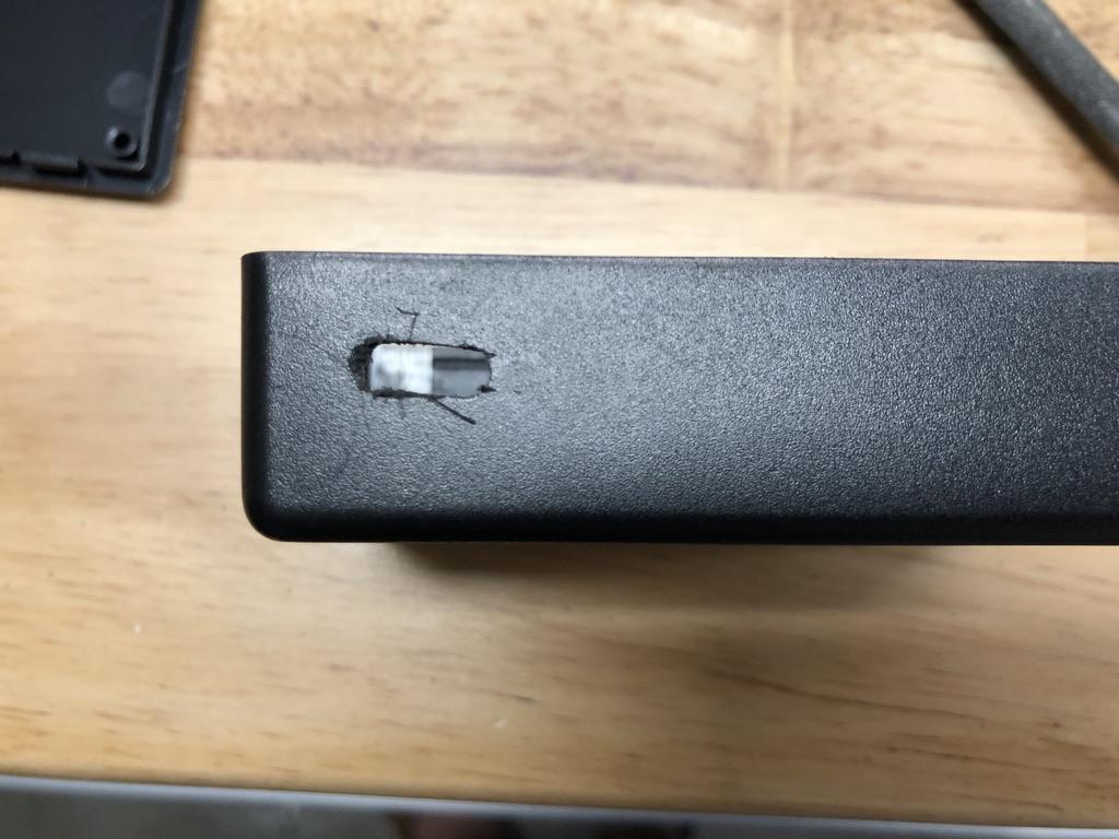
- Mark the space for the USB-C connector. My Qwiic Pro Micro board had headers soldered on it already so I put in into a piece of foam and marked it. If yours does not, lay it flat against the bottom of the case to mark the hole.
- Drill the marked holes and cut out the USB-C connector. The drilled holes should be big enough to let the screws go through.
- Cut a square of window screen a little bigger than the hole for the sensor. Cut out space on the window screen for the screw hole and the mounting post (see pictures above).
- Hot glue the screen into place.
Mount Oled and Sensor
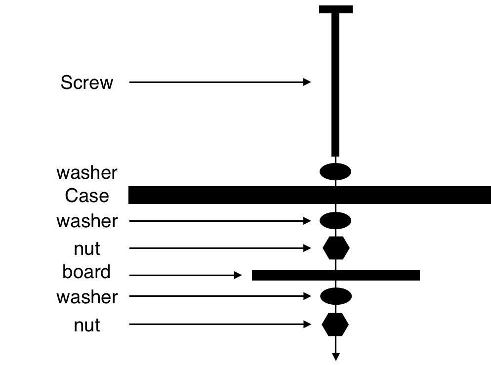
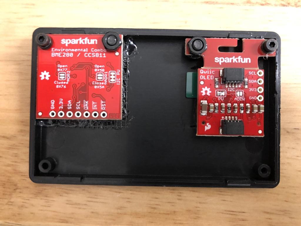
Mount the oled and environmental sensor in the case. The bigger screws go in the holes you drilled and the smaller screws go into the posts in the corner of the case lid. Use the washers for spacers. For the bigger screws, see the diagram above for clarification. You may need to use more than one washer for spacing.
Mount Arduino and Connect Components
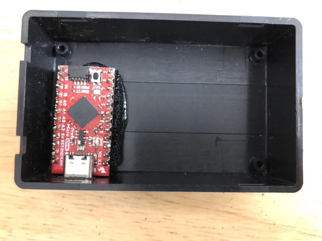
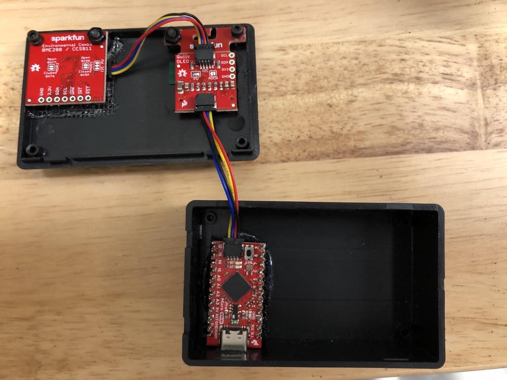
- My Qwiic Pro Micro board had headers soldered on it already so I put in into a piece of foam and glued it down. If yours does not have headers, glue it down to the bottom of the case. Ensure that there is enough room for the Qwiic cable to connect.
- Connect the components with the Qwiic connectors. Neither the order nor the side the Qwiic connector is on matter. See the pictures above for clarification.
- Now you can snap your project box together. Make that the Qwiic cables are connected tightly and do not get pinched.
Code
To get your Qwiic pro micro board up and running follow this tutorial.
Once that's done, the code is below of you can find it on GitHub here.
#include
#include
#include
#include

#define PIN_RESET 9
#define DC_JUMPER 1
#define CCS811_ADDR 0x5B //Default I2C Address

MicroOLED oled(PIN_RESET, DC_JUMPER);
CCS811 myCCS811(CCS811_ADDR);
BME280 myBME280;

void setup() {
    delay(100);
    Wire.begin();
    oled.begin();   // Initialize the OLED

    oled.clear(ALL); // Clear the display's internal memory
    oled.display();  // Display what's in the buffer (splashscreen)
    oled.clear(PAGE); // Clear the buffer.

    randomSeed(analogRead(A0) + analogRead(A1));
    //Initialize BME280
    //For I2C, enable the following and disable the SPI section
    myBME280.settings.commInterface = I2C_MODE;
    myBME280.settings.I2CAddress = 0x77;
    myBME280.settings.runMode = 3; //Normal mode
    myBME280.settings.tStandby = 0;
    myBME280.settings.filter = 4;
    myBME280.settings.tempOverSample = 5;
    myBME280.settings.pressOverSample = 5;
    myBME280.settings.humidOverSample = 5;
    CCS811Core::CCS811_Status_e returnCode = myCCS811.beginWithStatus ();
    //Calling .begin() causes the settings to be loaded
    delay(10);  //Make sure sensor had enough time to turn on. BME280 requires 2ms to start up.
    byte id = myBME280.begin(); //Returns ID of 0x60 if successful
    delay(10000);
    }

void print_data() {
    oled.setFontType(0);

    oled.setCursor(0, 0);
    oled.print("TMP");
    oled.setCursor(25, 0);
    oled.print(round(myBME280.readTempF()));

    oled.setCursor(0, 10);
    oled.print("HUM");
    oled.setCursor(25, 10);
    oled.print(round(myBME280.readFloatHumidity()));

    oled.setCursor(0, 20);
    oled.print("VOC");
    oled.setCursor(25, 20);
    oled.print(round(myCCS811.getTVOC()));

    oled.setCursor(0, 30);
    oled.print("BAR");
    oled.setCursor(25, 30);
    oled.print(round(myBME280.readFloatPressure()));

    oled.setCursor(0, 40);
    oled.print("CO2");
    oled.setCursor(25, 40);
    oled.print(round(myCCS811.getCO2()));

    oled.display();
    }

void loop() {
    delay(2000);
    //Check to see if data is available
    if (myCCS811.dataAvailable()) {
        //Calling this function updates the global tVOC and eCO2 variables
        myCCS811.readAlgorithmResults();
        //printData fetches the values of tVOC and eCO2

        float BMEtempC = myBME280.readTempC();
        float BMEhumid = myBME280.readFloatHumidity();

        //This sends the temperature data to the CCS811
        myCCS811.setEnvironmentalData(BMEhumid, BMEtempC);
    }
    print_data();
    delay(2000);
    }
Paste the code in the Arduino IDE and compile it. The screen should show the SparkFun logo for a few seconds, and then begin displaying the live conditions. The conditions update about every 2 seconds. Thanks for reading.
Got a Question?
Leave a comment or email me here