Hacking the Spy Video Trakr

The Trakr is a remote controlled robot equipped with a microphone and color video camera, speaker, a near infrared LED for night vision, an SD memory card slot for recording audio/video and 8MB of on board memory for storing downloadable and user designed programs. The remote control unit has control levers to drive the robot, a speaker and color video display so you can hear the audio picked up by the microphone and display the video transmitted by the camera, and several function buttons that can be used to control additional program functions of user designed programs. In this article we will demonstrate how to hack the Trakr. We will show you how to download and install the C language compiler for the Trakr. Next we’ll explain how to compile a simple program and install it on the Trakr and then run this simple program. Finally, we will demonstrate how to open up the Trakr, attach jumper pins to the GPIO connections on the mainboard of the Trakr and compile a simple program to flash an LED connected to the GPIO pins. You will be able to confidently call yourself an elite Trakr Hacker.
Download and Install the C Language Compiler for the Trakr
What's a compiler? Have you seen those geeky T-shirts that say "there are only 10 types of people in the world: those who understand binary, and those who don't?" If you find yourself scratching your head instead of laughing hysterically, then you don't understand binary. Computers, on the other hand, understand only binary. 1s and 0s. On and off.
I have heard of some people who can do binary code, or machine language in their heads, but the rest of us normal people would have a difficult time writing a computer program out of nothing but 1s and 0s. Instead we use a higher level language like C language to write software.
Have you ever been to a foreign country and didn't know the language? You can hire a translator to translate what you say into the language that the locals can understand. That's what a compiler does. Computers can't understand C language so, a compiler translates the software you write in C language into machine code, or the 1s and 0s that computers can understand.
You'll need to download and install the C language compiler so that you can write programs for the Trakr and compile your software into machine language that the Trakr can understand. The C Language compiler is included in a fairly complete software development kit (SDK) that the folks at Wild Planet call the "Primer." So, download the Primer and save it on your computer where it'll be easy to find by clicking the following link:
http://www.spygear.net/help/files/TRAKR_APP_PRIMER_V1.2.zip
Download and Install the C Language Compiler for the Trakr (continued)
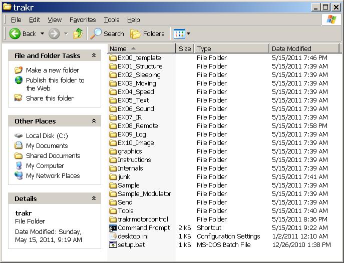
Make a new folder in the root directory of your hard drive (usually the C: drive) called C:\trakr. Then open the Trakr Primer zip file you downloaded from the Trakr web site and copy all the files and folders from the Trakr Primer zip file into your C:\trakr folder.
Download and Install the C Language Compiler for the Trakr (continued)

Next you'll need to update the environment variables to include the path to the Primer's compiler and tools. If you don't know what environment variables are, don't worry, you're just telling your computer where to find the compiler and the tools it needs to compile your Trakr programs.
Open a command prompt, which is a Windows text based interface. Go to Start->Programs->Accessories->Command prompt. You will see a flashing cursor after the ">" and you can type text based commands. When you're done typing a command press the Enter key on your keyboard to execute the command. At the command prompt, type the following commands:
cd trakr
setup
cd Internals
Download and Install the C Language Compiler for the Trakr (continued)
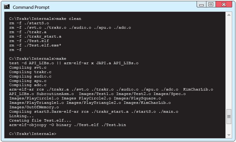
The compiler runs when you type "make" at the command prompt so you need to make sure you navigate to the folder where the makefile you want to run is located. The compiler then follows any instructions in that "makefile" to convert the "app.c" file (the text file containing the source code) into a TRAKR program.
The compiler only looks for the "app.c" file in the current folder so always name your source code app.c. Save your programs in separate folders with names which make sense. This helps to keep all the various "app.c" files organized. As shown in the screen shot, you'll want to run "make clean" in the C:\Trakr\Internals folder. It reports all the files it is removing before returning the prompt to you. Then type "make" at the command prompt and the compiler will use the "makefile" to assemble all the parts of your program (which may include many libraries, images and files specified by your code) into a .bin file to write to the TRAKR hardware.
At the "C:\Trakr\Internals>" prompt type:
make clean
make
Your newly compiled program or app for the Trakr is called "Test.bin" and the file will need to be copied to the Trakr. Make sure the Trakr is switched off and connect it to your computer using the yellow USB cable that came with the Trakr. Copy Test.bin to the APPS folder inside the Trakr folder. Disconnect the Trakr from your computer and switch the Trakr on. Switch the Trakr remote on, click the home button, and select Test from the menu. It's just a little app that tests all the various functions that your Trakr can do such as motor tests, screen functions and so on.
Installing the Jumper Pins on the Mainboard
In this section elite Trakr Hacker CPT_hans demonstrates how to install male header pins on the Trakr circuit board:
In this section, I'm going to briefly explain (with the aid of several photos) how I disassembled the Trakr and installed the headers. Please note that this project is not difficult, but it does require some patience and some soldering skill. If you are inexperienced or uncomfortable soldering on a printed circuit board, you can follow the instructions to disassemble the Trakr, and then take it to someone who can solder it for you.
The GPIOs and the A-to-D converter are inputs and outputs that can be used to control things. They share a .1" pitch header. The JTAG is a programming/testing port that uses a 2mm header. I plan on exploring the JTAG port, to see if I can access some capabilities there...but not everyone may be interested in doing that. I'm going to show both, but you can do just the GPIO if you want.
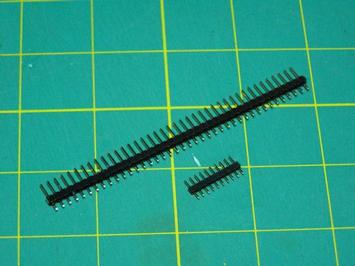
I ordered part # PRT-10112 ($0.95) from Sparkfun http://www.sparkfun.com for the JTAG header. It's 10 pins; we only need 7, so we can just snip off the extras. For the GPIO, I ordered part # PRT-00116 ($1.50). It is a 40-pin header. Since we only need 9 pins, that one part is enough for 4 Trakrs!
Installing the Jumper Pins on the Mainboard (continued)
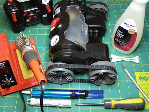
You'll need these additional items for this project:
- Trakr (duh!)
- #1 Phillips screwdriver
- Fingernail polish remover
- Cotton swabs
- Exacto knife (or similar hobby knife)
- Soldering iron
- Solder
- Vacuum desoldering tool (aka 'solder sucker'...hey, nobody's perfect, and you may have to fix a mistake!)
- Trakr (duh!)
- #1 Phillips screwdriver
- Fingernail polish remover
- Cotton swabs
- Exacto knife (or similar hobby knife)
- Soldering iron
- Solder
- Vacuum desoldering tool (aka 'solder sucker'...hey, nobody's perfect, and you may have to fix a mistake!)
Installing the Jumper Pins on the Mainboard (continued)
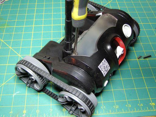
Start by removing the two screws for the back cover. Throughout this project, be mindful of the antenna, and don't break it!
Installing the Jumper Pins on the Mainboard (continued)
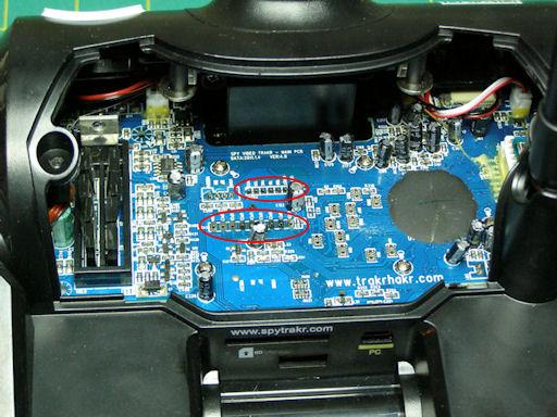
When that's done, you can look in at the mainboard, and see where we're going to install the headers.
Installing the Jumper Pins on the Mainboard (continued)
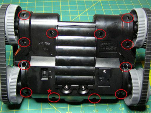
You'll want to fold the antenna over and then flip the Trakr over so you can get at the screws that fasten the Trakr case together. Use a philips screwdriver to remove all the case screws (you can ignore the battery and reset compartment screws). There are a total of 12 screws to remove. Note that the screw marked with a star is shorter than the other 11, so keep track of it.
Installing the Jumper Pins on the Mainboard (continued)
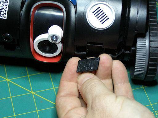
Once the cover screws are removed, you can pull the upper and lower housings apart. When you do, the emblem on the front will fall out. No worries. There's also another piece behind it that will now be loose. Set them both aside, and remember to replace them when reassembling the Trakr.
Installing the Jumper Pins on the Mainboard (continued)
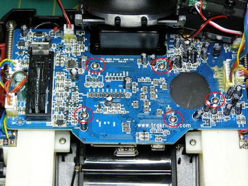
With the upper housing moved aside, you can see the shiny screws holding in the mainboard. Resist the temptation and don't remove them yet!
Installing the Jumper Pins on the Mainboard (continued)
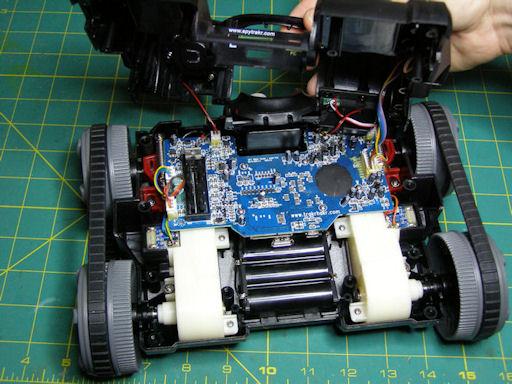
Once the cover screws are removed it's easy to lift the cover enough to see most of the main board. When opening up the cover remember to be careful. There are a number of wires that are connected between the cover and the mainboard. The connectors for the wires are modular, but to make the Trakr more rugged, the connectors have been glued together. I don't know what kind of glue Wild Planet used, but it must be UFO technology from Area 51! It's tough stuff! This is where the fingernail polish remover and patience are employed.
Installing the Jumper Pins on the Mainboard (continued)
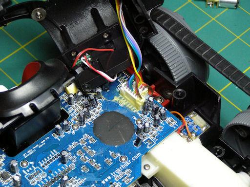
With a cotton swab, apply fingernail polish remover to the glue to soften it up. It will probably take more than one application. Allow the polish remover time to soak into the glue. Use the hobby knife to trace along the connector joints, and to peel the glue away from the connectors. Note that the connectors also have two tabs molded into the plastic so they'll latch together. I used the knife to release the tabs, once the glue was cleaned away.
Installing the Jumper Pins on the Mainboard (continued)
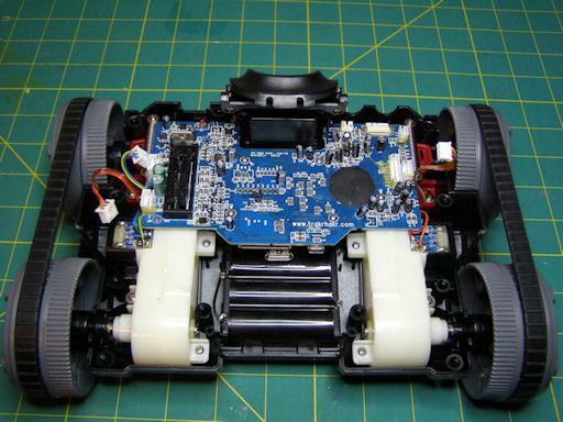
With the connectors unglued and separated, you can now set aside the upper housing. If while trying to separate the connectors, you end up pulling the whole thing off the board, don't fret. The pins on the board will still be okay. If you look at the pic below, you'll notice that I accidentally pulled the whole connector for the speaker off of the left front leaving the pins sticking up from the board. It was easy to reattach the connectors to the naked pins once I got the connector separated. I just used a hot glue gun to reattach it to the mainboard.
A quick note. Gelfling6 commented on this instructable and pointed out the following:
"The connectors for the speaker, and the push button, are not critical, since both are non-polar. The MIC connector, however, IS! Make sure you put the socket back exactly the same direction, or you could (a) fry the MIC element, and (b, Obviously) the MIC will not pick up anything!"
If you accidently remove the whole connector, try to reconnect it back in its original orientation on the circuit board.
The Trakr Hakr community are interested in improving their Instructables. If you notice an error or something they've forgotten, let them know in the comments section.
Installing the Jumper Pins on the Mainboard (continued)
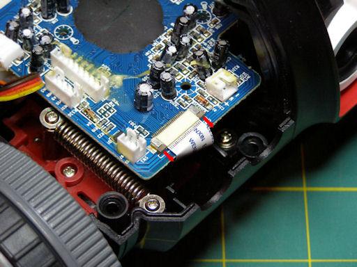
Before you take the mainboard screws out, there's another connector to unhook. This flat white ribbon cable is on the right front of the Trakr, and is for the camera assembly. It's a pressure-type connector that holds the ribbon cable against the contacts of the socket. To release, slide the little brown tabs (they're actually connected and run underneath the ribbon cable) forward about 1/8"...the cable will slide right out.
Installing the Jumper Pins on the Mainboard (continued)
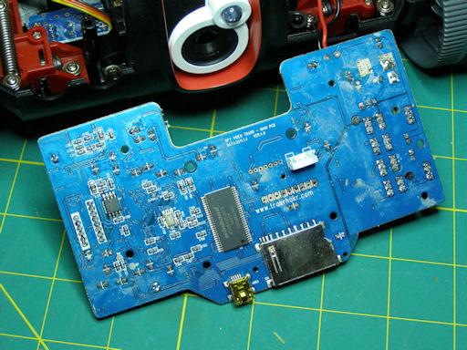
Remove the five mainboard screws, and unhook the connector to the USB port from the bottom. I left the power leads from the battery pack soldered on, since I had enough freedom of movement even with them connected.
Installing the Jumper Pins on the Mainboard (continued)
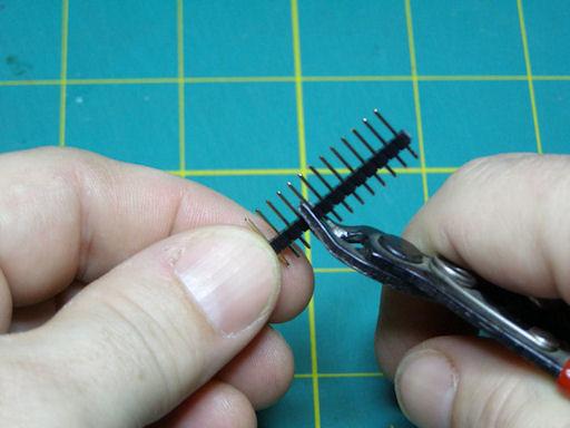
At this point, it's a simple matter to insert the headers into the holes on the mainboard, and solder them in. Good solder joints are smooth and shiny like these. Ensure that none of them are soldered to their neighbor (solder bridge).
Installing the Jumper Pins on the Mainboard (continued)
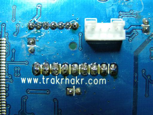
At this point, it's a simple matter to insert the headers into the holes on the mainboard, and solder them in. Good solder joints are smooth and shiny like these. Ensure that none of them are soldered to their neighbor (solder bridge).
You can also use Wire Glue http://www.wireglue.us/ as an alternative to soldering.
Now reverse the disassembly process to put your Trakr back together!
You can also use Wire Glue http://www.wireglue.us/ as an alternative to soldering.
Now reverse the disassembly process to put your Trakr back together!
Installing the Jumper Pins on the Mainboard (continued)

So you ask, "I have pins, now what do I use for plugs?" You can order connectors online to fit the headers, although Sparkfun doesn't carry any. I did some scrounging in my parts box and found that various cables from old computers will connect to the headers. The connector on the left is an audio connector used to hook CDROM drives to sound cards or motherboards. It fits the GPIO spacing. The connector on the right is the type used for internal audio connections, like video capture cards to sound cards, etc. This will fit the JTAG spacing.
Installing the Jumper Pins on the Mainboard (continued)

I'm not saying these connectors will meet all your needs, but it at least you can modify them, and it gives you an idea of what to look for in your junk box. In the pic below, I have two CDROM audio cables on the GPIO...this would give me A-to-D and five GPIO connections; certainly enough to play around with. Other .1" connectors from an old computer case or motherboard (e.g. front panel switches, USB headers, chassis fans) should be of compatible spacing as well.
Use the GPIO Pins to Flash LEDs (Light Emitting Diodes)

The test to control a device using the GPIO connections is to switch LEDs on and off by pressing buttons on the TRAKR remote. I used one of the CDROM audio cables that I mentioned above. I wired the components directly to the cable; I didn't really think it was worth a circuit board. The 100ohm resistor drops the voltage to 1.6...perfect for the LEDs.
You can see how it was soldered in the upper left portion of the picture. When you run the trakrmotorcontrol app and no button is pressed, nothing illuminates. When button A is pressed, the green LED lights up; when button B is pressed, the red LED lights up.
C Language code:
////////////////////////////////////////////
//LED flash program for Spy Video TRAKR
//Program scans to see if button A was
//pressed on TRAKR remote and sets GPC0 high
//and GPC1 low to send current through LED
//in forward bias direction (switched on).
//
//If button B is pressed, it sets GPC0 low
//and GPC1 high to send current through
//LED in reverse direction (switched off).
///////////////////////////////////////////
#include "svt.h" //include Official API
#include "JAPI.h" //include "Secret sauce" API
#define GPC0 (1<<0) //bitmask for pin GPC0 = 00000001
#define GPC1 (1<<1) //bitmask for pin GPC1 = 00000010
#define GPC2 (1<<2) //bitmask for pin GPC2 = 00000100
#define GPC3 (1<<3) //bitmask for pin GPC3 = 00001000
#define GPC4 (1<<4) //bitmask for pin GPC4 = 00010000
#define GPC5 (1<<5) //bitmask for pin GPC5 = 00100000
#define GPC6 (1<<6) //bitmask for pin GPC6 = 01000000
#define GPC7 (1<<7) //bitmask for pin GPC7 = 10000000
int keyState; //define "keystate" as integer
void Start()
{
JAPI_SetIoOutputMode(GPC0+GPC1);//Set output mode for pins GPC0 and GPC1
}
bool Run()
{
keyState=GetRemoteKeys(); //TRAKR remote control key pressed
//assign to keystate
if (keyState > 0)
{ //if keystate is greater than 0
if(keyState&KEY_INPUT1)
{ //Button A pressed (motor forward)
JAPI_SetIoHigh(GPC0);//Set GPC0 pin high (3.3v)
} else {
JAPI_SetIoLow(GPC0); //Switch off pin GPC0
}
if(keyState&KEY_INPUT2)
{ //Button B pressed (motor reverse)
JAPI_SetIoHigh(GPC1);//Set GPC1 pin high (3.3v)
} else {
JAPI_SetIoLow(GPC1); //Switch off pin GPC1
}
if(keyState&KEY_HOME)
{ //if Home button pressed
return false; //this will end the loop
}
}
return true; //loop will repeat until false
}
void End()
{ //Program end - switch off both pins
JAPI_SetIoLow(GPC0+GPC1);
}
Make file:
# Makefile for TRAKR Toy
# Trakr Project
TRACKR_PATH = C:/Trackr
PROGRAM_NAME = trakrmotorcontrol
PRETTY_NAME = trakrmotorcontrol
OUTPUT_PATH = ./Intermediate
OUTPUT_NAME = $(OUTPUT_PATH)/$(PROGRAM_NAME).elf
INTERNALS_PATH = ../Internals
SOURCES = app.c
S_OBJECTS = $(OUTPUT_PATH)/app.o
OBJECTS = $(S_OBJECTS) $(INTERNALS_PATH)/trakr.a
SHELL = sh
CC = arm-elf-gcc
AS = arm-elf-as
BIN = arm-elf-ld
LD = arm-elf-ld
TOPMEMORY=0xFFE7C000
CFLAGS = -O0 -I../Internals/Include -I../Internals -Wall -gstabs+
TARGET_FLAG = -mcpu=arm926ejs -mapcs-32 -mlittle-endian -specs=specs.semi
LDFLAGS = -T ../Internals/WJ_APP_8M.ld -Wl,--defsym -Wl,__stack_base=$(TOPMEMORY) -Wl,-Map -Wl,$(basename $@).map -nostartfiles -static
all: prebuild $(OUTPUT_NAME) postbuild
$(OUTPUT_NAME): $(OBJECTS)
@echo "Linking... "
@echo "Creating file $@..."
@$(CC) -u _start -o $@ $(INTERNALS_PATH)/trakr_start.a $(OBJECTS) $(TARGET_FLAG) $(LDFLAGS)
$(OUTPUT_PATH)/app.o:app.c Makefile
@echo "Compiling $<"
@$(CC) -c -o "$@" "$<" $(TARGET_FLAG) $(CFLAGS)
.PHONY: clean prebuild postbuild
clean:
$(RM) -f $(PROGRAM_NAME).bin
$(RM) -f "$(PRETTY_NAME).bin"
$(RM) -f $(OUTPUT_PATH)/app.o
$(RM) -f $(OUTPUT_NAME)
$(RM) -f $(MKDEPFILE)
postbuild:
arm-elf-objcopy -O binary $(OUTPUT_NAME) "$(PRETTY_NAME).bin"
@if [ -d "E:/" ] ; then \
cp "$(PRETTY_NAME).bin" e:/APPS/ ; \
fi
prebuild:
# End of Makefile
When you compile the above code with the above make file, this will create a Trakr App file called "trakrmotorcontrol.bin" and the file will need to be copied to the Trakr. Make sure the Trakr is switched off and connect it to your computer using the yellow USB cable that came with the Trakr. Copy trakrmotorcontrol.bin to the APPS folder inside the Trakr folder. Disconnect the Trakr from your computer and switch the Trakr on. Switch the Trakr remote on, click the home button, and select trakrmotorcontrol from the menu.
You can use the trakrmotorcontrol app to control many different types of electrical devices...motors, lights, relays, etc.
You're an Elite TRAKR Hacker!
Congratulations! You may now call yourself an elite Trakr Hacker. You now know how to download and install the C language compiler for the Trakr. You can use the compiler to compile programs for the Trakr. You can install custom programs on the Trakr and run them. For you more daring Trakr Hackers, we’ve shown you how to open up the Trakr and connect external devices to the GPIO connections on the mainboard such as an LED and control them using software you have written, compiled, and installed on the Trakr. Happy hacking!