Hacking LaserCAD
LaserCAD
If like me, you've upgraded your Laser Cutter to use one of the DSP controllers sold by LightObject.com, such as the AWC608 or as I did, the X7 DSP (AWC708), you have probably become very familiar with LaserCAD, the sole proprietary software that works with the DSP controller.
If so, you have probably also had that moment like I did, where I found limitations and bugs in the software that caused me to wonder why I paid so much for the controller! In fairness, having used it now for several weeks, it does seems to be substantially better than the software that shipped with the Laser Cutter, and from all reports, the combination of hardware and software is worth the expense. If for no other reason, having software that has reasonable English -- no need to try to translate Chinese is worth quite a bit.
But there are limitation, and in this article I will give you a hack that works around two of the more annoying limitations or bugs in LaserCAD. This hack works with version 7.78, the latest version (as of March 2016), and version 7.77. I have only tested my code with these two versions.
The Bugs
This hack addresses two bugs in LaserCAD:
- Font Selection doesn't work properly in some cases
- Only English (and probably Chinese) Text will be drawn properly
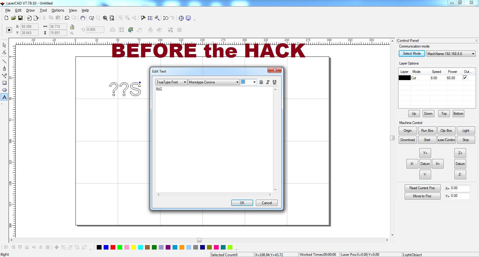
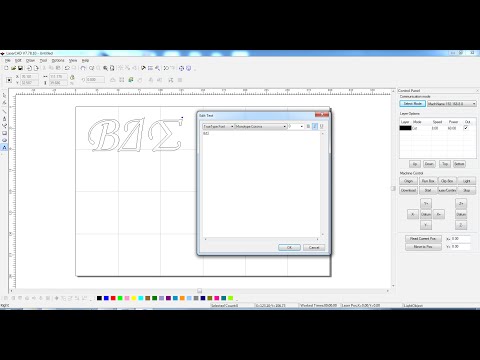
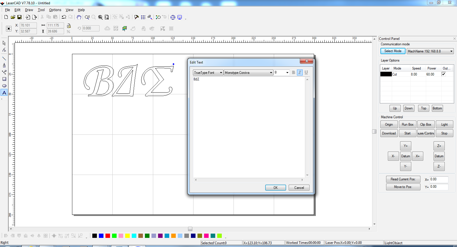
The image below shows text that was entered in LaserCAD 7.78 with the Monotype Corsiva font. The text consist of 3 letters from the Greek Alphabet. On the right you will see what it looked like when it was entered, and to the left you will see how LaserCAD rendered the text: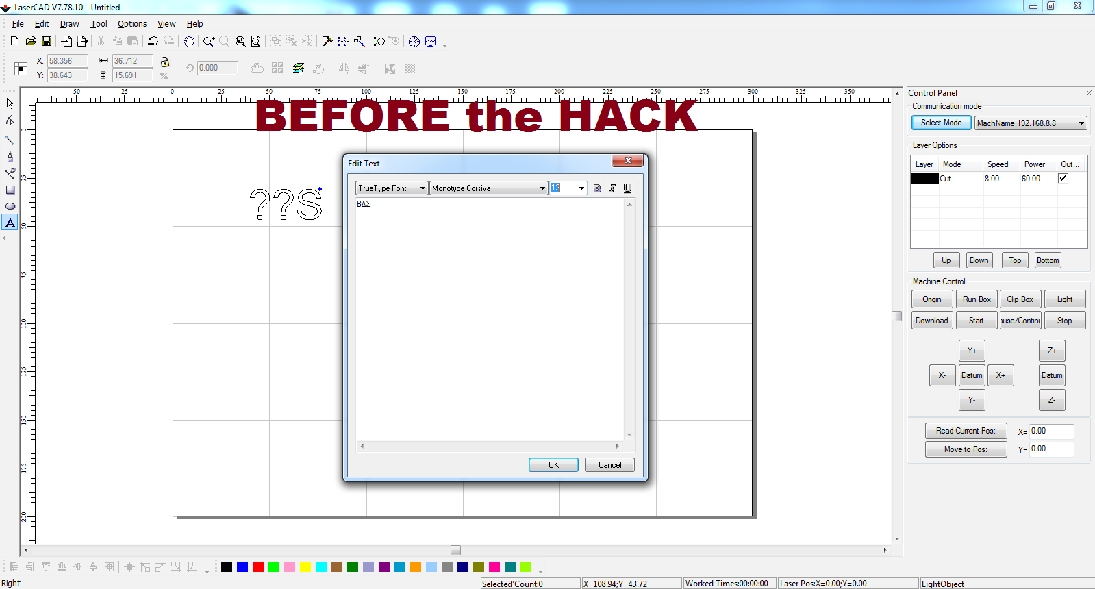
Notice that the non-English characters printed mostly as question marks. And that it did not render in the Monotype Corsiva font.
Of course if you've seen these bugs, you may have already learned to work around them. You can for example create drawings using Inkscape, DeltaCAD, AutoCAD, or CorelDraw (probably many others), save the files as DXF files, and then import them into LaserCAD and in some cases re-adjust the size. But there is a better way. We can actually fix this bug.
Fix Lifetime
Before I introduce the fix, let me first say that I hope this is hack has a very short lifetime. That is, I hope the developers of LaserCAD will release their own fix soon. But I'm not one to wait! I offered my services as a professional software developer, free of charge, to help them fix these bugs. My offer was ignored and I was told they were working on more important features. (Features that I would like to have in the product!) That's fine. It would have taken about 2 hours tops to find and fix these bugs in the source code, but instead I've fixed it without the source code. In the final step of this article I will explain how the fix works so that should they be so inclined, the developers of LaserCAD will understand the bugs and how to fix them quickly.
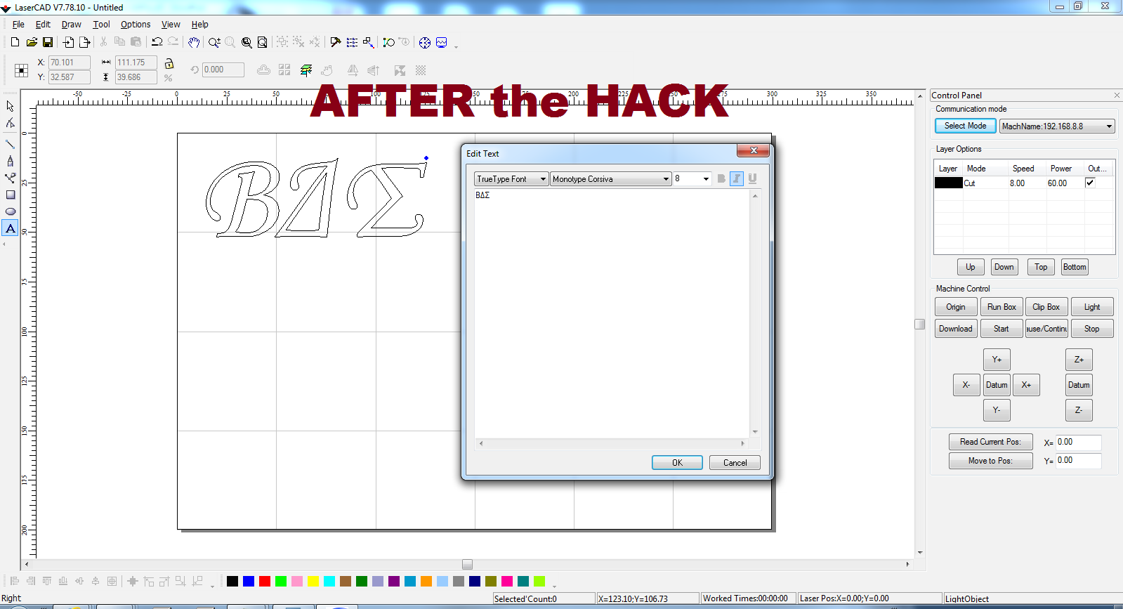
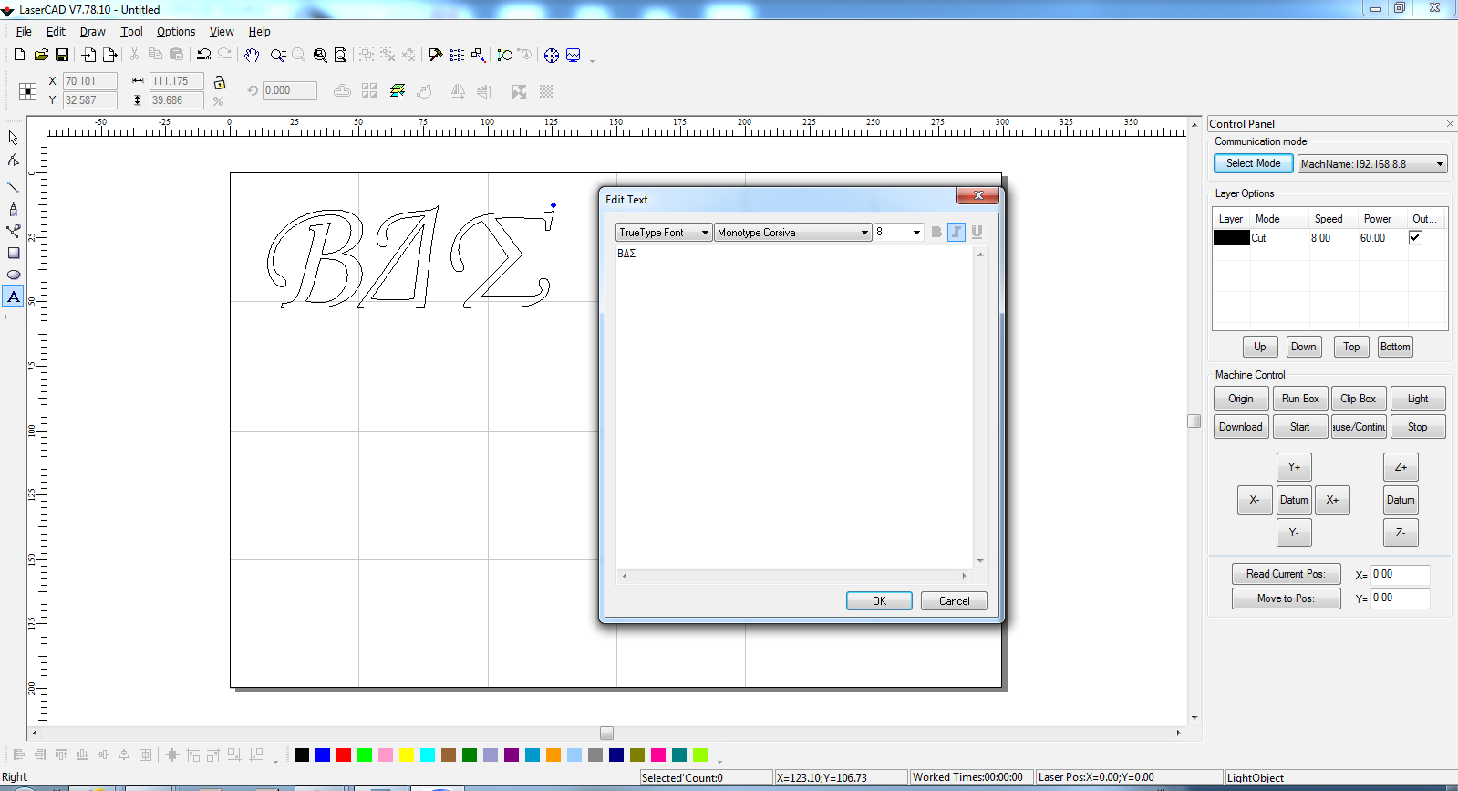
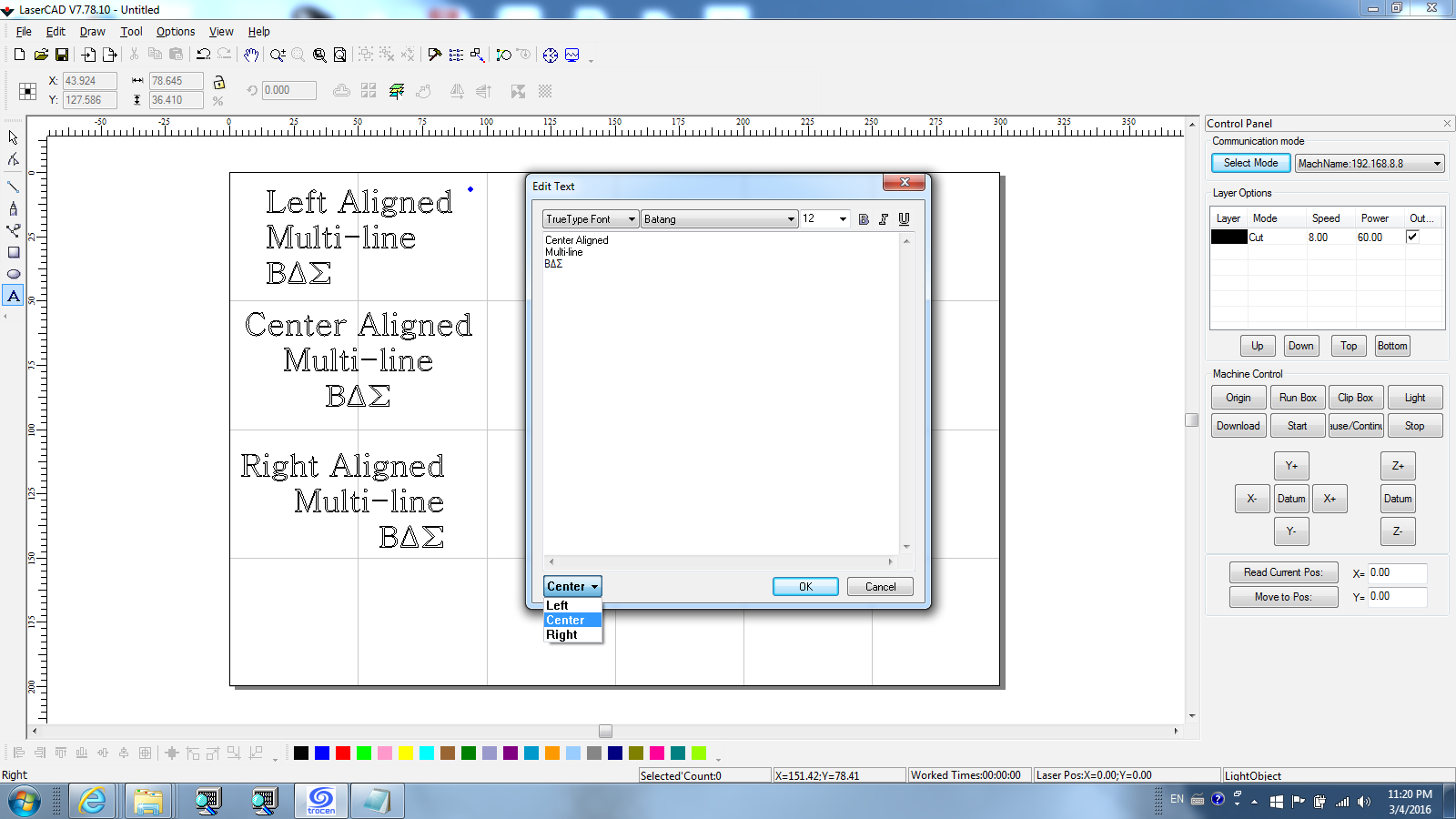
Once the hack is applied, you will be able to select fonts like Monotype Corsiva and have them work the first time. (Note that with that particular bug, you can get the font to work if you know enough about it. In the case of Monotype Corsiva, the font only exists as an Italic font, so if you don't click the Italic button it will revert to a San Serif font. Other fonts have their own characteristics that are not obvious and lead to the same problem.) Also, you will be able to enter non-English text as is shown below:
Applying the Hack...
The Hack
The hack consists of a new DLL that must be "injected" into LaserCAD.exe. The DLL implements "hooks" on key Windows APIs in order to affect the necessary fixes to the code. Follow the steps below to apply the fix. The attached video demonstrates how to carryout each step. Be sure to watch it full screen in order to be able to adequately see what is happening:
Prerequisite
There are a number of ways that our fix DLL can be injected into the LaserCAD process, but by far the easiest way to do it is to create a copy of LaserCAD.exe that purposefully and permanently imports the new DLL. For this we will use CFF Explorer from ntcore.com. CFF Explorer is an extremely useful tool written by Daniel Pistelli. To install it, visit http://www.ntcore.com/exsuite.php and click on "Download the Explorer Suite". Once downloaded, run ExplorerSuite.exe and follow the prompts to install it on your machine. When you are done with all of the following steps you may remove Explorer Suite (via the Control Panel | Programs) if you have no further need for it..
The Fix DLL
After this you will need the fix itself. It is called LaserCADFix.dll and it can be downloaded from my website here: http://www.andrewlsandoval.com/Articles/LaserCADFix/LaserCADFix.dll.
After downloading LaserCADFix.dll copy it to the AWCPrograms folder under LaserCAD. If you installed LaserCAD in c:\, copy the file to C:\LaserCAD\AWCPrograms\.
Importing LaserCADFix.dll into LaserCAD.exe
With the fix file in place, use Windows explorer ( Windows Key + E ) to browse to the LaserCAD\AWCPrograms folder (usually c:\LaserCAD\AWCPrograms\) if you did not already have window open to it. Then right-click on LaserCAD.exe. Then click on "Open with CFF Explorer".
Next click on Import Adder on the left panel of CFF Explorer. To the right of the Modules box, click the Add button. Select LaserCADFix.dll from the list of files and click Open.
In the Exported Functions window you will see the entry "00000064 - ImportMe". Click on this, and then click the button above it labeled "Import By Ordinal". This will copy "00000064 - ImportMe" to the Imported Functions list on the right-hand side.
Next click the "Rebuild Import Table" button. This will add our DLL to the LaserCAD.exe import list.
Finally, click the Save button (it looks like an old floppy disk and is on the top left, second button from the left). You will be presented with a prompt that says "Overwrite original file?" Click on "No." In the Save As dialog, enter the file name LaserCADFixed.exe, and click on Save. You can now close CFF Explorer (and uninstall it if you'd prefer.)
Making it easily accessible
There are now two copies of LaserCAD. If you run LaserCAD.exe it will function the same as it always had, bugs and all. If you run LaserCADFixed.exe our fix will be applied and you can enter text with the proper font selected and in non-English characters if needed. If you right-click on LaserCADFixed.exe in the Explorer window you can select either "Pin to Taskbar" or "Pin to Start Menu". This will create a link on the taskbar or Start Menu for easy access. You can also select Copy, and then on your Desktop, right-click and select "Paste Shortcut". Be sure to give the shortcut a name that helps you to know that this copy opens the fixed version of LaserCAD.
How It Works...
Font Selection
LaserCAD uses Microsoft's GDI+ library for managing fonts. When you select a font from the drop down list on the Edit Text box a list of available fonts is displayed. After you enter text and click Ok, LaserCAD copies the Font Family name from the drop list and passes to GDI+ using code that looks something like this:
Gdiplus::Font font(pwzFontFamily, fSize, iStyle);
Here pwzFontFamily is the text string pulled from the Font ComboBox. fSize is a float with the size from the font size drop-down, and iStyle has flags for Bold, Italic, and Underline (etc.)
When this constructor is invoked, the Microsoft code (source is available) calls GdipCreateFont() passing similar information. If a matching font can not be found and error code is returned and the Microsoft code then switches to a generic San Serif font as shown below:
As mentioned previously, in order to get the correct font from LaserCAD as-is, you have to know if the font you've selected needs Bold, Italic, or (rare) Underline included in the style list passed to GdipCreateFont. A font like Monotype Corsiva for example only exists as an Italic. If Gdiplus::FontStyle::FontStyleRegular is passed to GdipCreateFont, as will be the case if one of the Bold, Italic, or Underline buttons is not checked, GdipCreateFont will fail to find the Italic-only Monotype Corsiva and the generic San Serif font will be used.
The Font Selection Fix
To fix this problem we will use the following code to if the selected font support Bold, Italic, Underline, or Normal:
Once we know which styles the font support we can disable the buttons that do not apply. If the font does not support FontStyle::FontStyleRegular but does support Bold or Italic, one of these will be checked. If only one is supported it will also be disabled so that it can't be shut off.
To be able to do this, I intercept the Edit Text Dialog's DialogProc callback. This could be done via subclassing, but a different technique was used here which is beyond the scope of this article. The original code could be fixed by altering the existing DialogProc to do the same thing.
Text Input and Rendering
The bug with entering non-ANSI (non-English) text occurs because the DialogProc reads the text from the Edit control using an ANSI function, like GetDlgItemTextA. The window itself (as with most Edit controls) is capable of holding Unicode text but the call to GetDlgItemTextA will not be able to represent the characters properly and will replace them with question marks or other substitute characters.
To fix this, since I can't easily change the existing code, I have placed a hook on the Windows API EndDialog. My hook function is shown below: 
It works by reading the text from the Edit control before the Dialog Box is closed and storing that text in a global variable: g_wstrLastKnownText.
The final step is to hook the GDI+ function that is used to render the text: GdipAddPathString. When it is invoked, I simply replace the text that is passed to it with the string I saved from the Edit control. Sadly, the text that was being passed to GdipAddPathString by LaserCAD had to be reconverted back into a Unicode string before it could be sent to GdipAddPathString, but, the damage had already been done. Here is my replacement for GdipAddPathString:
With that done, it is now possible to enter non-ANSI text in the Edit control and have it rendered properly for Laser Cutting / Engraving!
The Needed Fix
The LaserCAD code could be fixed by simply using Unicode (wchar_t) instead of ANSI (char) character buffers when reading the string from the Edit control. As long as it never converted to an ANSI string it will render properly when passed to GdipAddPathString.
Conclusion...

While I hope this hack serves you well, I also hope it is short-lived. It will be better for all if the code requires no hacks to work properly. In the meantime enjoy it.
I also hope that it demonstrates that we don't have to accept bugs in software. When worse comes to worse, there are ways of resolving bugs, even though it does require learning some real "hacking" skills. ;) And while you can't really do this without a knowledge of C, C++, and Assembly language as well system internals, I hope it inspires a few coders out there to dig a little deeper -- push themselves to accomplish new things, and above all else, think carefully through the design of your software and focus on producing quality code.
Please also check out my other two articles entered in the Full Spectrum Laser Contest. The first will show you how to make an Arduino based Water Flow Rate Monitor and Alarm, along with Windows software for monitoring and control, to keep your CO2 laser tube constantly cooled while in use.
The second article will teach you how to make a Water Chiller and Arduino based Thermostat to keep the water cooling your laser tube cold.
Thank you!
* NOTE: Though I use the word "hack", technically this is not the kind of computer "hacking" that people often fear. Most of the commercial software products that I have worked on over the last two decades employ similar techniques to those I used here, in order to either enhance 3rd party products or to control them for legitimate business purposes.
A New Feature...
Text Alignment
As I was reviewing the code for this "fix" yesterday, I came to the realization that the GDI+ call utilized by LaserCAD to add text always sets the text using left-alignment. Furthermore, since I already have code intercepting the Edit Text Dialog box procedure, I am able to add new controls to the dialog box -- which means I can let you change the text alignment..
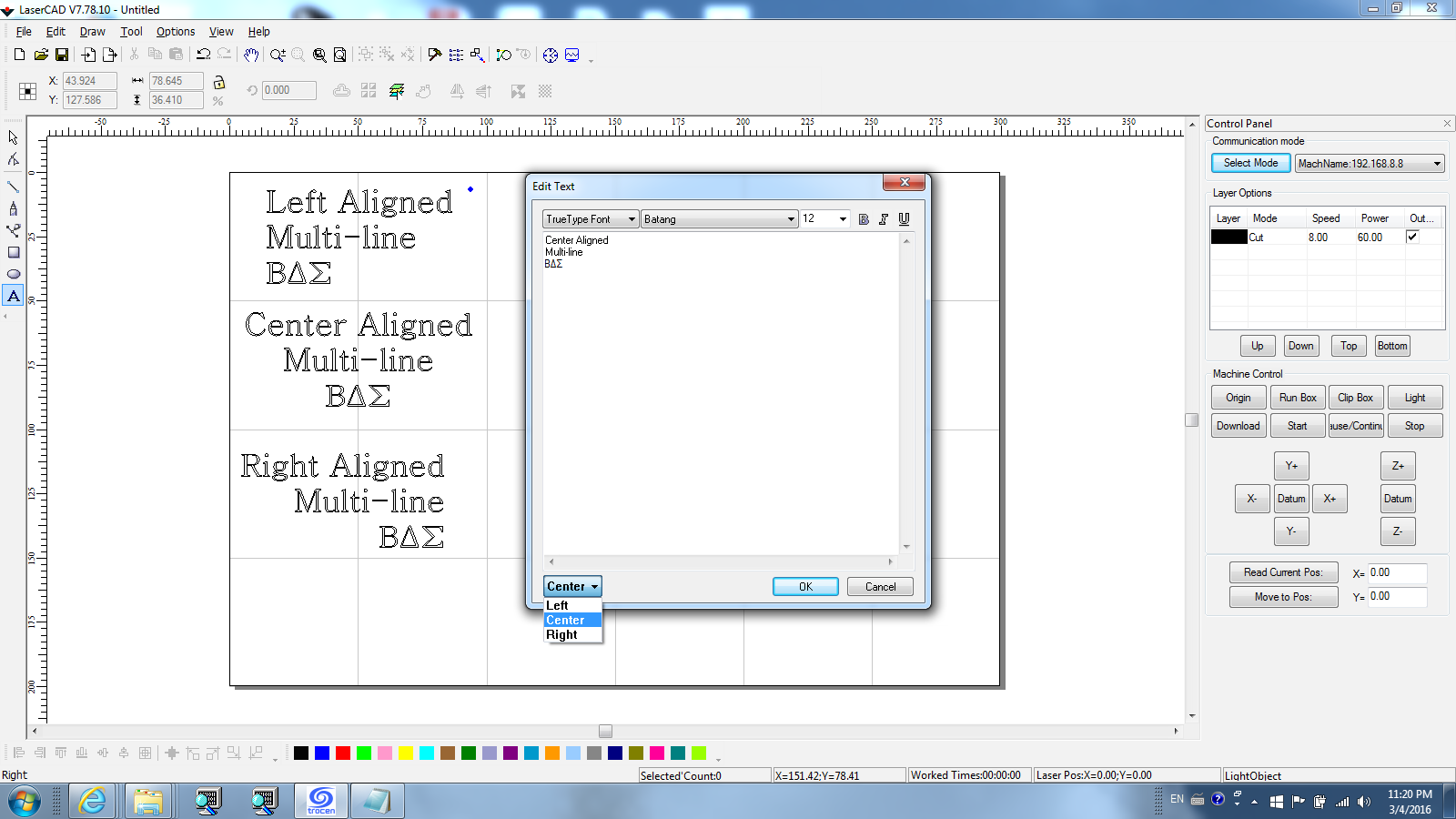
You will notice that I elected to use a combo box (drop down list) for selecting Left, Center, or Right alignment. I could have also used checkboxes, but I wanted to utilize as little space as possible on the dialog box, as well as keep the code as simple as possible.
Version 1.0.0.2
This new version of LaserCADFix.dll has been uploaded to my server. If you have already downloaded version 1.0.0.1, you can download the new version here, and simply copy it over the top of the old version in your LaserCAD\AWCPrograms\ folder. If you followed all of the installation instructions after March 4, 2016 you will already have version 1.0.0.2.
Future Possibilities
I spent a few hours this evening trying to produce text on circle. It was able to draw it on the screen, but not into a path that LaserCAD could send to the DSP controller. Though it would likely be very easy to add this feature if the source code to LaserCAD were available, I decided it was not something I could finish within just a few hours, and at the moment I have other projects that need my attention. Nevertheless, I may still update this "hack" in the future to provide this ability. Without the source it will require me to add a new button to the main screen, a dialog for parameters, and then rather than using a hook on a GDI+ function I'll have to invoke Win32 APIs to automate adding the characters one at a time through the Edit Text dialog, change the angle of each letter, and reposition it. It should be doable -- if you are ambitious enough you may want to try doing it yourself! Of course, I hope given time new releases of LaserCAD will add this type of functionality -- the easy way. :) Though, if I were in charge of priorities, I think grayscale image engraving should be on the top of the list. After all, the DSP controller can control laser intensity (power level), so it should be able to turn shades of gray in a bitmap to power levels as it engraves the bitmap. If they hadn't gone to fairly extreme measures to keep secret the file format read by the DSP controller, I probably would have written a tool to generate grayscale image files for the machine.