HackerBox 0046: Persistence
by HackerBoxes in Circuits > Arduino
6208 Views, 17 Favorites, 0 Comments
HackerBox 0046: Persistence
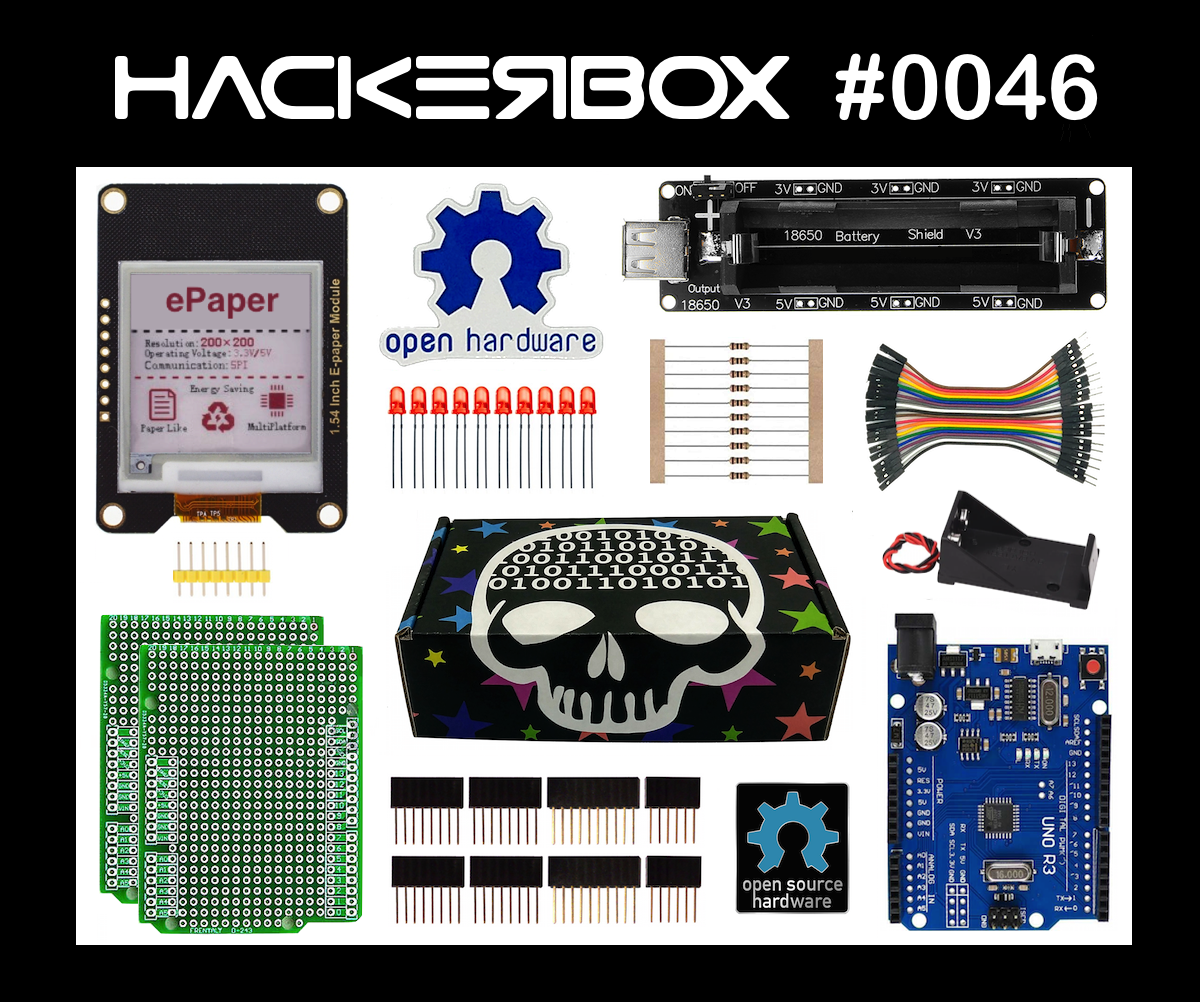
Greetings to HackerBox Hackers around the world! With HackerBox 0046, we are experimenting with persistent electronic paper displays, LED persistence of vision (POV) text generation, Arduino microcontroller platforms, electronic prototyping, and rechargeable battery power banks.
This Instructable contains information for getting started with HackerBox 0046, which can be purchased here while supplies last. If you would like to receive a HackerBox like this right in your mailbox each month, please subscribe at HackerBoxes.com and join the revolution!
HackerBoxes is the monthly subscription box service for enthusiasts of electronics and computer technology - Hardware Hackers - The dreamers of dreams.
HACK THE PLANET
Content List for HackerBox 0046
- ePaper Module
- Arduino UNO with MicroUSB
- Two UNO Prototyping Shields
- USB 18650 Battery Power Bank
- Diffused Red 5mm LEDs
- 560 Ohm Resistors
- Male-Female DuPont Jumper Wires
- 9V Battery Holder
- Open Hardware Sticker
- Exclusive Open Hardware Lapel Pin
Some other things that will be helpful:
- 9V Battery
- Soldering iron, solder, and basic soldering tools
- Computer for running software tools
Most importantly, you will need a sense of adventure, hacker spirit, patience, and curiosity. Building and experimenting with electronics, while very rewarding, can be tricky, challenging, and even frustrating at times. The goal is progress, not perfection. When you persist and enjoy the adventure, a great deal of satisfaction can be derived from this hobby. Take each step slowly, mind the details, and don't be afraid to ask for help.
There is a wealth of information for current and prospective members in the HackerBoxes FAQ. Almost all of the non-technical support emails that we receive are already answered there, so we really appreciate your taking a few minutes to read the FAQ.
Arduino UNO
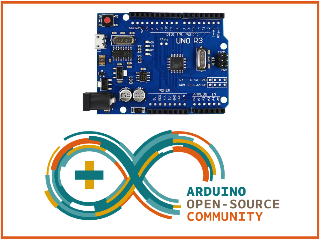
This Arduino UNO R3 is designed with easy of use in mind. The MicroUSB interface port is compatible with the same MicroUSB cables used with many mobile phones and tablets.
Specification:
- Microcontroller: ATmega328P (datasheet)
- USB Serial Bridge: CH340G (drivers)
- Operating voltage: 5V
- Input voltage (recommended): 7-12V
- Input voltage (limits): 6-20V
- Digital I/O pins: 14 (of which 6 provide PWM output)
- Analog input pins: 6
- DC current per I/O Pin: 40 mA
- DC current for 3.3V Pin: 50 mA
- Flash memory: 32 KB of which 0.5 KB used by bootloader
- SRAM: 2 KB
- EEPROM: 1 KB
- Clock speed: 16 MHz
Arduino UNO boards feature a built-in USB/Serial bridge chip. On this particular variant, the bridge chip is the CH340G. For the CH340 USB/Serial chips, there are drivers available for many operating systems (UNIX, Mac OS X, or Windows). These can be found through the link above.
When you first plug the Arduino UNO into a USB port of your computer, a red power light (LED) will turn on. Almost immediately after, a red user LED will usually start to blink quickly. This happens because the processor is pre-loaded with the BLINK program, which we will discuss further below.
If you do not yet have the Arduino IDE installed, you can download it from Arduino.cc and if you would like additional introductory information for working in the Arduino ecosystem, we suggest checking out the instructions for the HackerBoxes Starter Workshop.
Plug the UNO to your computer using a MicroUSB cable. Launch the Arduino IDE software.
In the IDE menu, select "Arduino UNO" in under tools>board. Also, select the appropriate USB port in the IDE under tools>port (likely a name with "wchusb" in it).
Finally, load up a piece of example code:
File->Examples->Basics->Blink
This is actually the code that was preloaded onto the UNO and should be running right now to blink the red user LED. Program the BLINK code into the UNO by clicking the UPLOAD button (the arrow icon) just above the displayed code. Watch below the code for the status info: "compiling" and then "uploading". Eventually, the IDE should indicate "Uploading Complete" and your LED should start blinking again - possibly at a slightly different rate.
Once you are able to download the original BLINK code and verify the change in the LED speed. Take a close look at the code. You can see that the program turns the LED on, waits 1000 milliseconds (one second), turns the LED off, waits another second, and then does it all again - forever. Modify the code by changing both of the "delay(1000)" statements to "delay(100)". This modification will cause the LED to blink ten times faster, right?
Load the modified code into the UNO and your LED should be blinking faster. If so, congratulations! You have just hacked your first piece of embedded code. Once your fast-blink version is loaded and running, why not see if you can you change the code again to cause the LED to blink fast twice and then wait a couple of seconds before repeating? Give it a try! How about some other patterns? Once you succeed at visualizing a desired outcome, coding it, and observing it to work as planned, you have taken an enormous step toward becoming an embedded programmer and hardware hacker.
Electronic Paper Display Technology
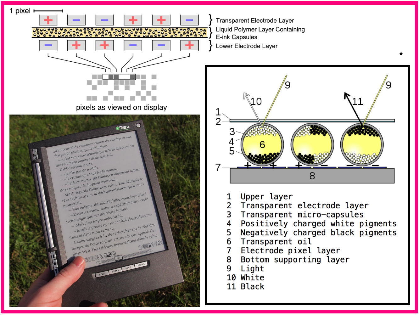
Electronic Paper, ePaper, electronic ink, or e-ink technologies enable display devices that mimic the appearance of ordinary ink on paper. Electronic paper display are generally persistent in that the image remains visible even without power or with the control circuitry removed or shut down. Unlike conventional backlit flat panel displays that emit light, electronic paper displays reflect light like paper. This can make them more comfortable to read and provide a wider viewing angle than most light-emitting displays.
The contrast ratio approaches newspaper with newly developed displays (since 2008) being slightly better still. An ideal ePaper display can be read in direct sunlight without the image appearing to fade.
Flexible electronic paper uses pliable plastic substrates and plastic electronics for the display backplane. There is ongoing competition among manufacturers to provide full-color electronic paper support.
Multicolor EPaper Module
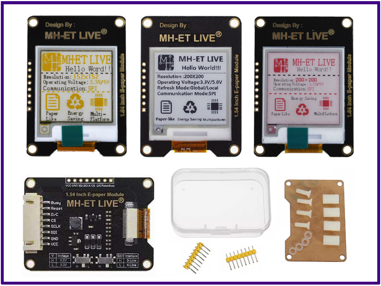
The MH-ET LIVE 1.54-inch ePaper Module can display both black and red ink. The module is referred to in the example and documentation as the black/white/red (b/w/r) 200x200 electronic paper display (EPD).
The display technology is Microencapsulated Electrophoretic Display (MED), which uses tiny spheres where the charged color pigments are suspending in the transparent oil and move into view depending on applied electronic charges.
The ePaper screen can display patterns by reflecting ambient light, so it operates without a backlight. Even in bright sunlight, the ePaper screen provides high visibility with a 180 degree viewing angle.
Use of MH-ET Module with Arduino UNO:
- Install Arduino IDE (if not already installed)
- Use Library Manager (Tools->Manage Libraries) to install Adafruit GFX Library
- Use Library Manager to install GxEPD (NOT GxEPD2)
- Open file->examples->GxEPD>GxEPD_Example
- Uncomment the line to include GxGDEW0154Z04 (1.54" b/w/r 200x200)
- Wire UNO to EPD: Busy=7, DC=8, Reset=9, CS=10, DIN=11, CLK=13, GND=GND, VCC=5V
- Set EPD Switches BOTH to “L”
- Download GxEPD_Example sketch from IDE to UNO as usual
Another library with demo code (supplied from the EPD manufacturer) can be found here. Note that these demos (and some other examples available online) have different pin assignments than those used above in the GxEPD example. Most notably, pins 8 and 9 are often reversed.
Arduino UNO Prototyping Shield
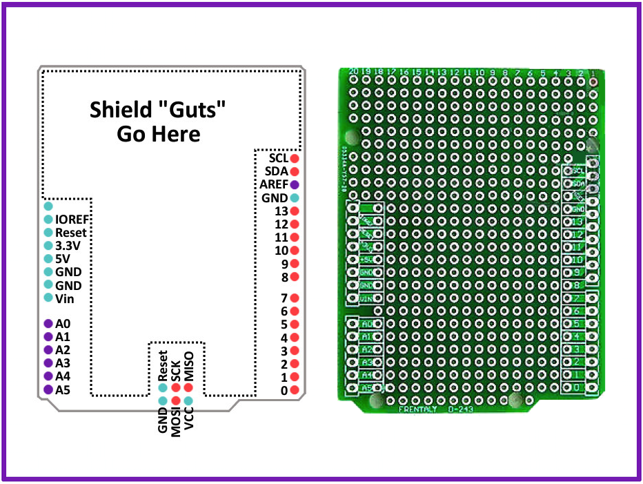
An Arduino UNO Prototyping Shield fits directly onto an Arduino UNO (or compatible) board just like any other shield. However, the Arduino UNO Prototyping Shield has a general-purpose "perf-board" area in the middle where you can solder on your own components to construct your own custom shield. Simply solder the headers in at the outside rows of the shield such that it can plug right on top of the UNO. The plated holes next to the headers connect to the header signals so that the lines from the UNO can be easily connected into your custom circuitry.
Seven LED Setup on Prototype Shield
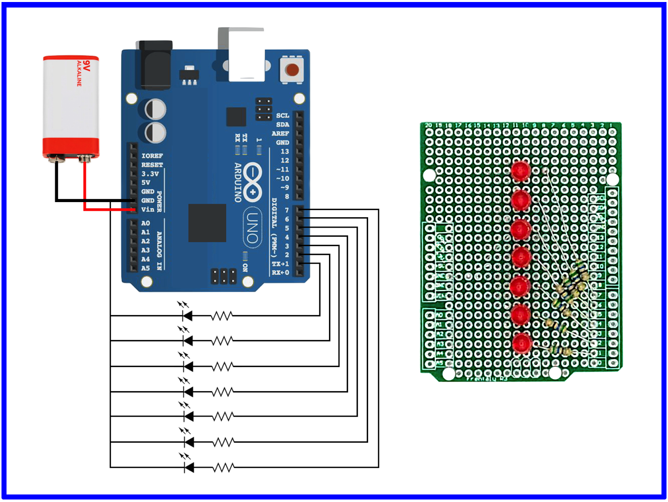
An Arduino Prototype Shield can be used to support the illustrated circuit. The circuit has I/O pins 1-7 of the Arduino connected to seven LEDs. Each LED is wired in-line with its own current limiting resister, which in this example are 560 Ohm resistors.
Note that the short pin of each LED needs to be oriented towards the GND pin of the Arduino. The resistors can each be oriented in either direction. The 9V batter holder can be connected to make the project "portable" but must be wired to the Vin pin (not to 5V or 3.3V).
Once the circuit LEDs and resistors are wired up, experiment with the blink example sketch by changing the pin number to various values between 1 and 7.
Finally, try out the knight_rider.ino sketch attached here for a flashback from the 80s.
Downloads
Persistence of Vision
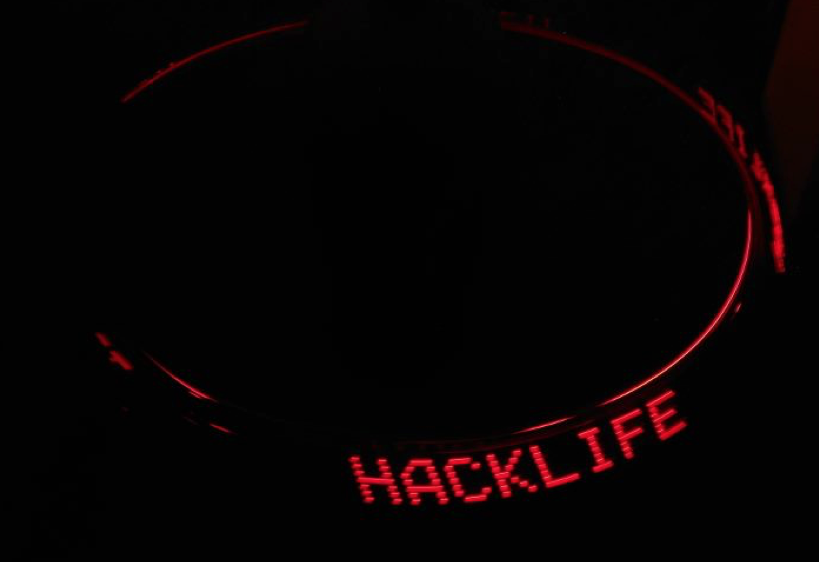
Persistence of vision [VIDEO] refers to the optical illusion that occurs when visual perception of an object does not cease for some time after the rays of light proceeding from it have ceased to enter the eye. The illusion is also described as "retinal persistence", "persistence of impressions", or simply "persistence". (wikipedia)
Try out the POV.ino sketch included here on the "Seven LED" hardware setup from the last step. In the sketch, experiment with different message text and timing parameters to get various effects.
Inspiration: Arduino POV Project from Ahmad Saeed.
Photo Credit: Charles Marshall
Downloads
USB 18650 Battery Power Bank
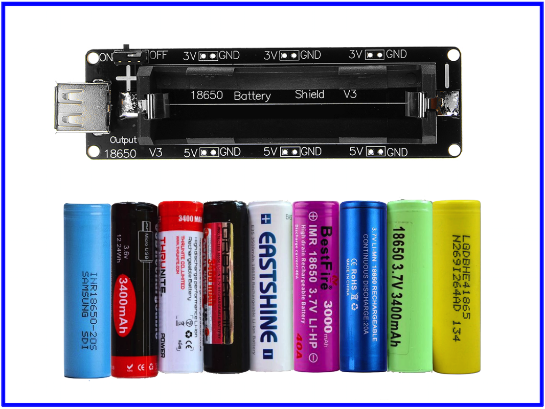
Just pop a 18650 Lithium-Ion cell into this baby to make your own rechargeable "Power Bank" for use with various 5V and 3V projects!
You can find these common 18650 Lithium-Ion cells from various sources, including this one from Amazon.
Power Bank Module Specifications:
- Input (Charging) Supply: 5 to 8V via micro USB port up to 0.5A
- Output power:
- 5V via USB Type A port
- 3 connectors to deliver 3V up to 1A
- 3 connectors to deliver 5V up to 2A
- LED Status Indicator
- Green = battery charged
- Red = charging)
- Battery protection (overcharging or over-discharging)
- ATTENTION: There is no reverse-polarity protection!
Live the HackLife

We hope are enjoying this month's HackerBox adventure into electronics and computer technology. Reach out and share your success in the comments below or on the HackerBoxes Facebook Group. Also, remember that you can email support@hackerboxes.com anytime if you have a question or need some help.
What's Next? Join the revolution. Live the HackLife. Get a cool box of hackable gear delivered right to your mailbox each month. Surf over to HackerBoxes.com and sign up for your monthly HackerBox subscription.