Hacked E-Card

Description of Project
In this instructable I will be demonstrating how you can easily manipulate sound by using Arduino programming and hacking into an electronic card. This project will include the use of a protosnap mini and some wiring.
You will need:
You will need a:
1-Electronic Card
1-Protosnap Mini by SparkFun
1-Arduino as a controller
1-BreadBoard
1 Sharp Knife
4-Jumper Wires
2-Aligator Clips
1-Relay
Theory:
If we connect the wires correctly we will be able to manipulate the sound by using an Arduino sketch
Step 1 Open Your Card



You can get any kind of electronic card as long as it makes sound. Along the edge of the card you will find a gap between two sides. Take note of this because this is where you will be making the cut.
Step 2 Start Cutting


Once you located the gap begin cutting in between until you open up the card and see an electronic device inside.
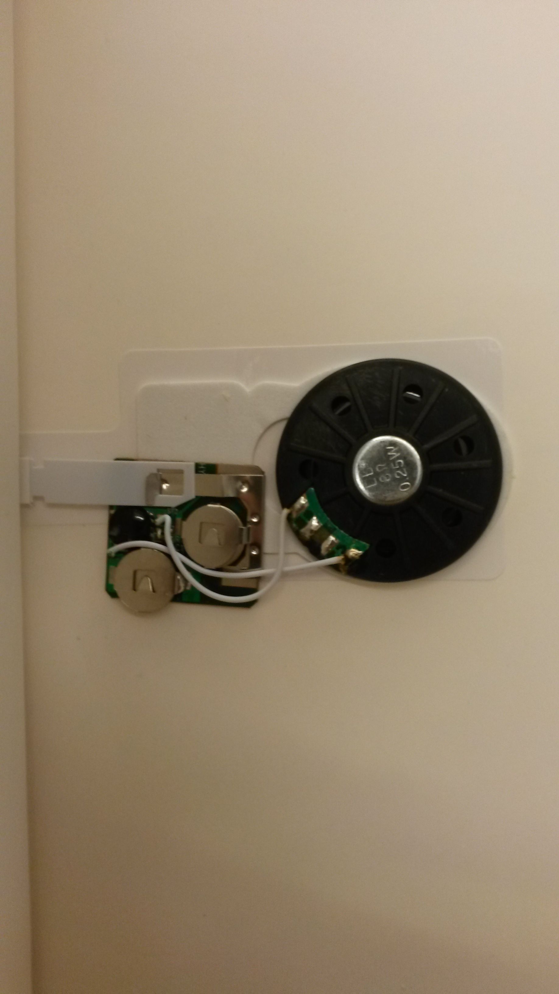
Step 3 Locate Electrical Component

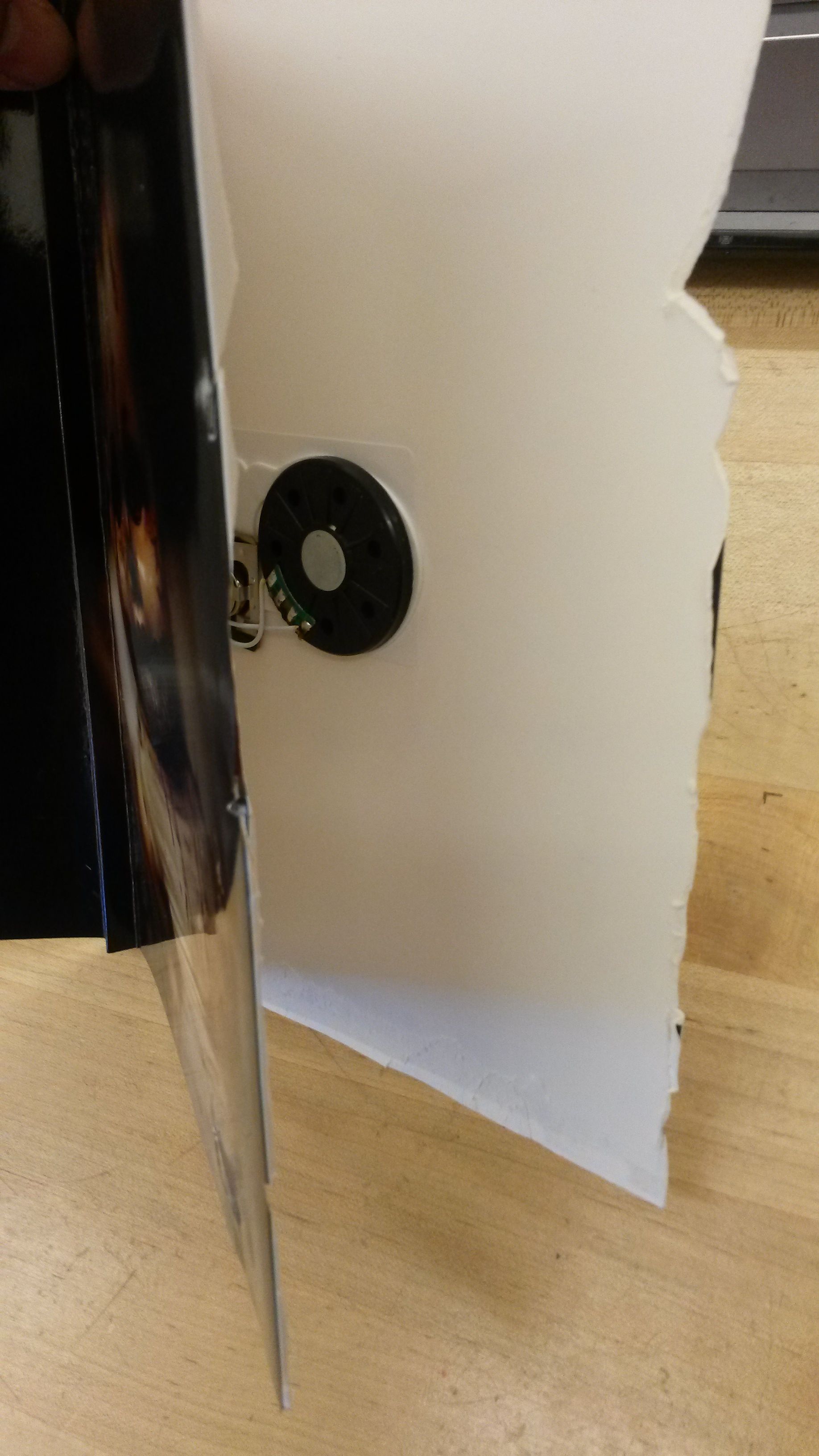
When you look into the card you should be able to see the electronic component of the card that makes the sound. Start identifying parts that trigger the sound.
Step 4 Unlatch the Lever!
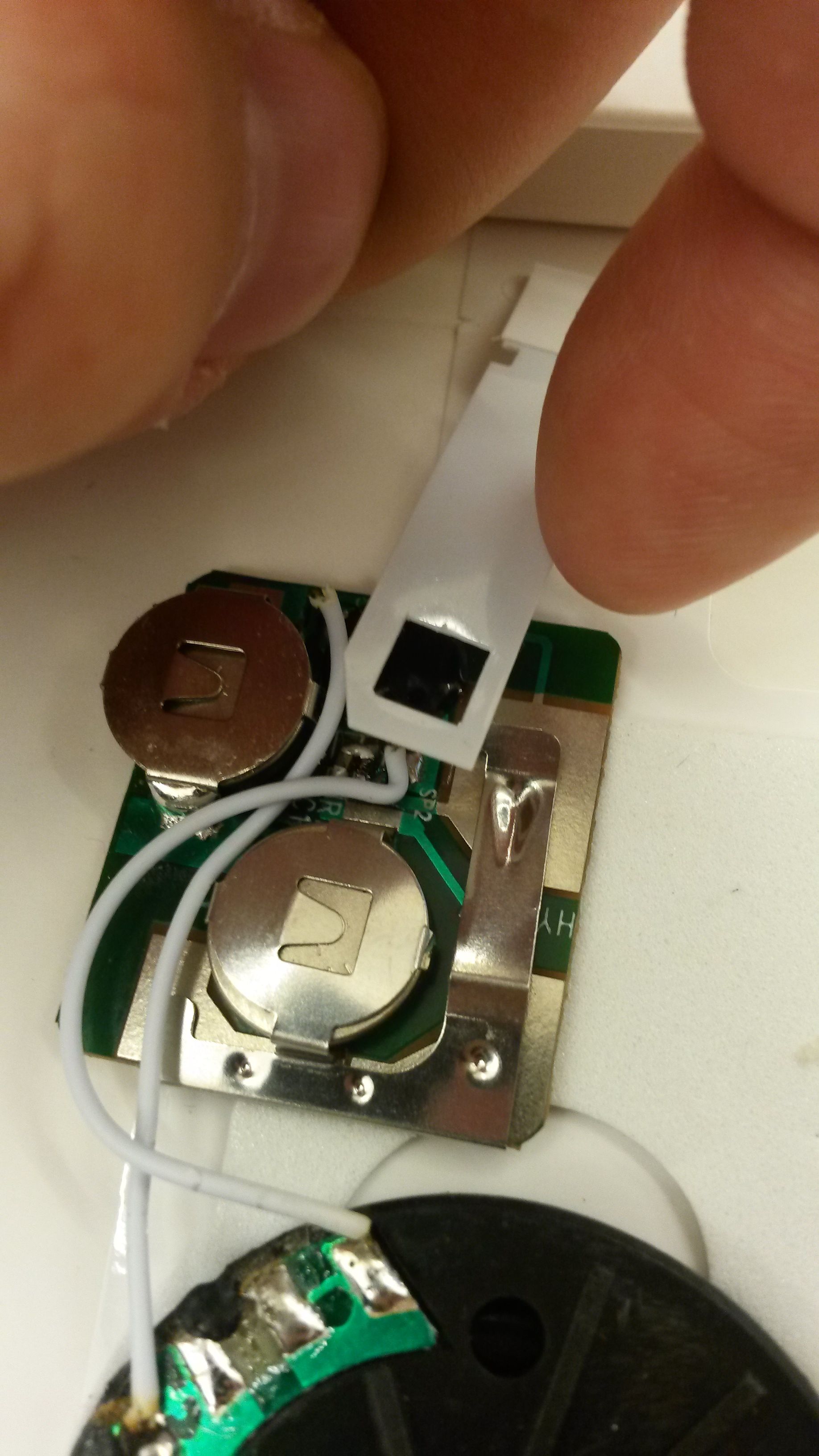
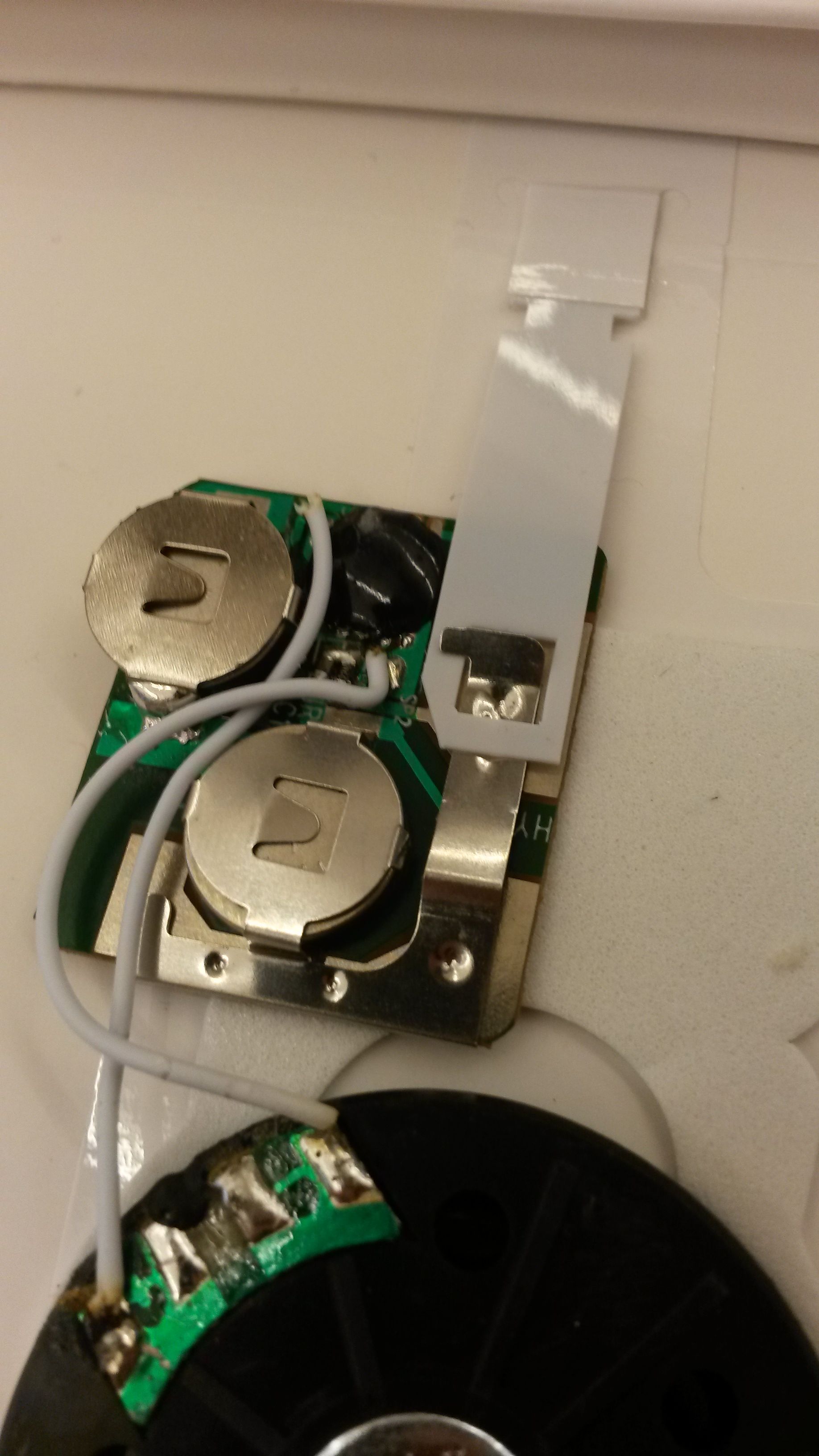
You will notice a lever that when you remove the sound will be played. This acts as something to inhibit the card from making sounds so if you unlatch it the sound should come again. Try testing this so you know what part of the component is creating the sound
Step 5 Hook Up Your Protosnap
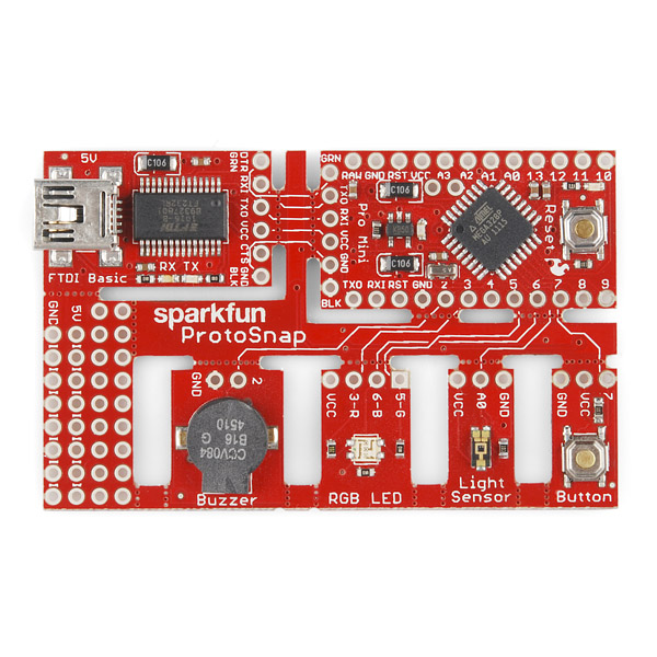
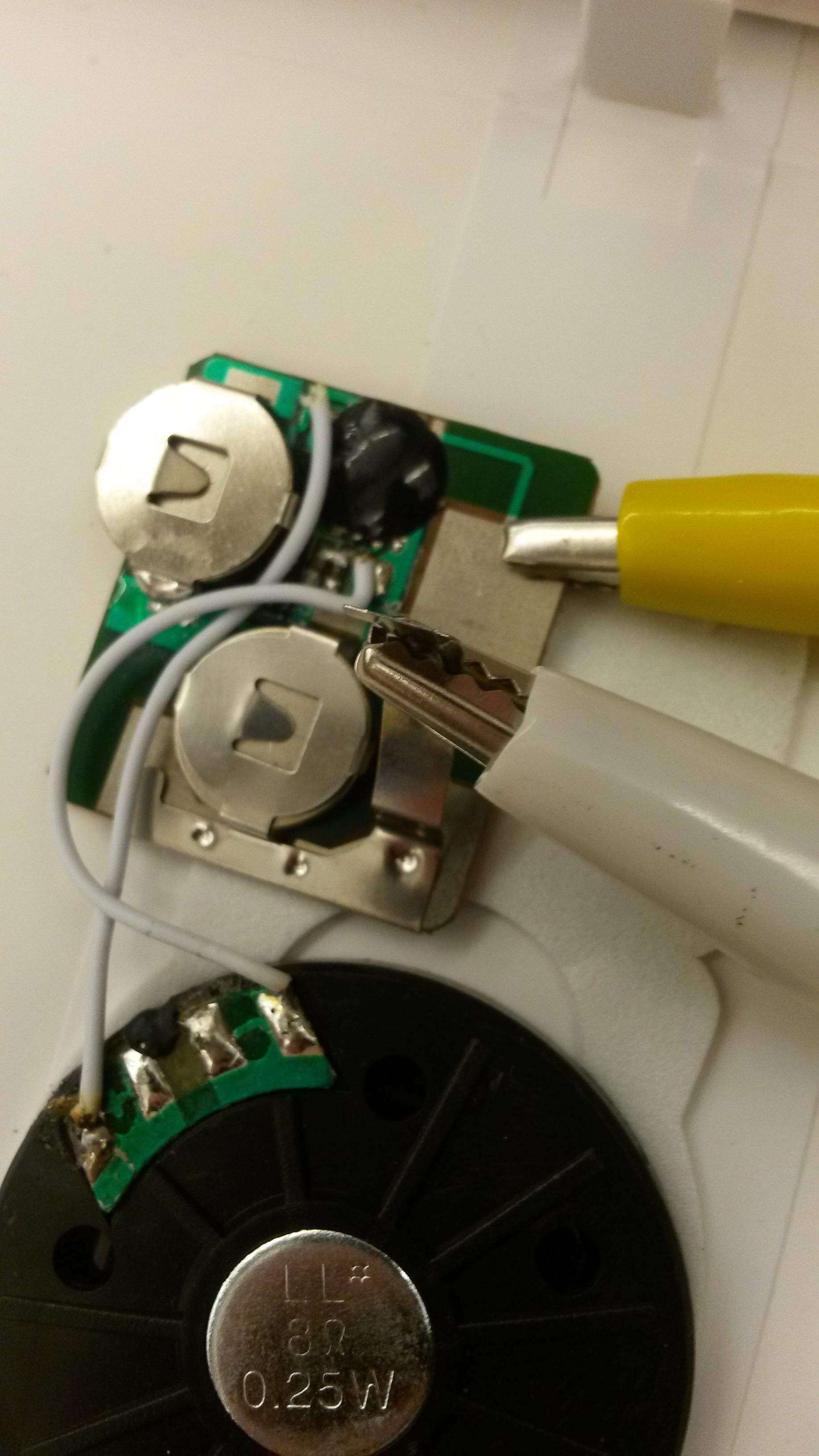
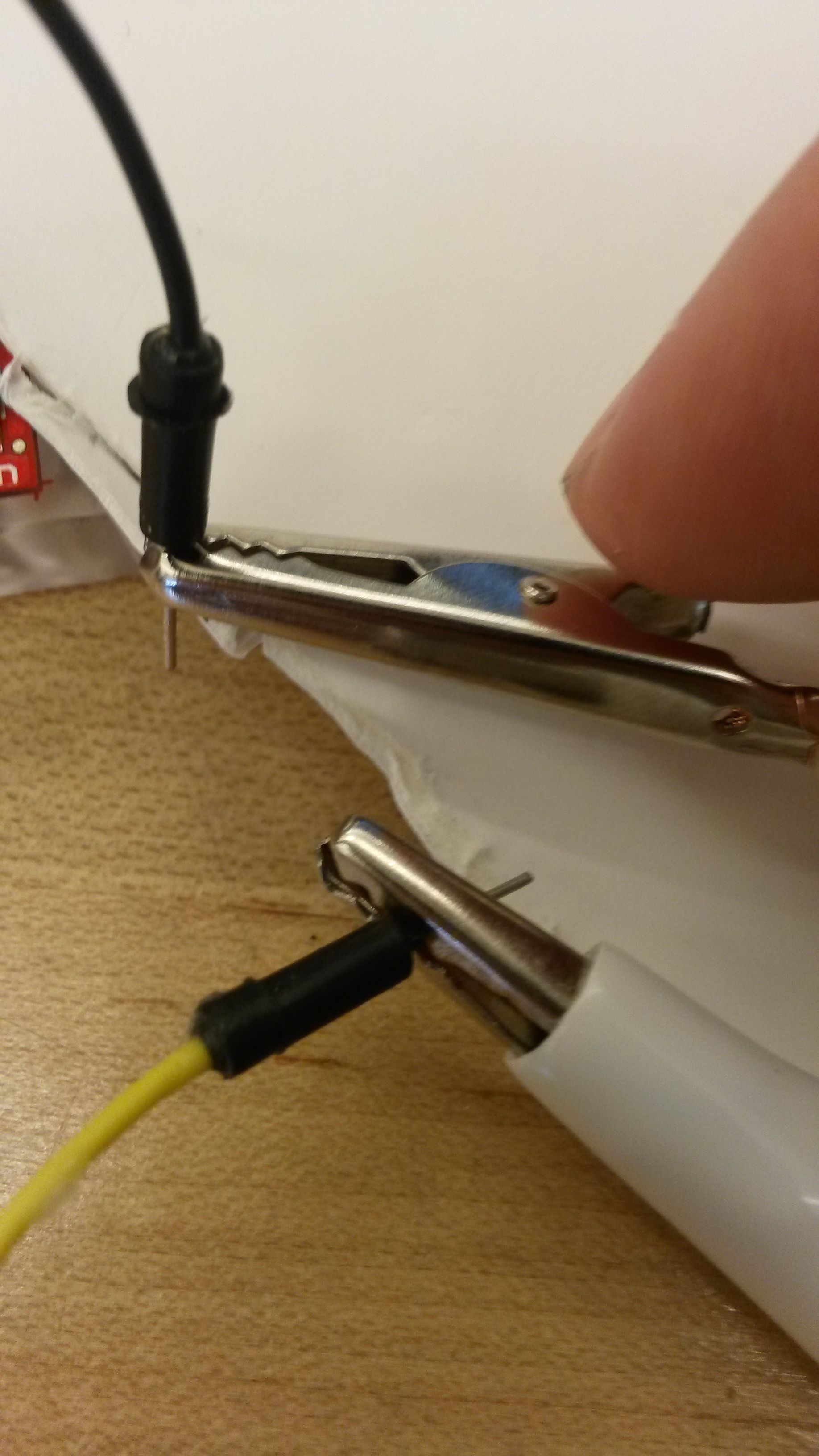
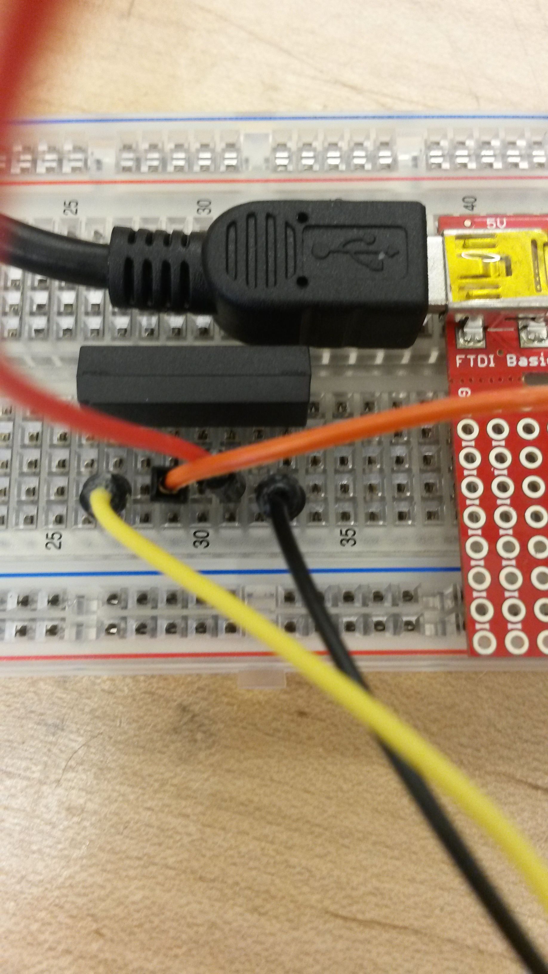
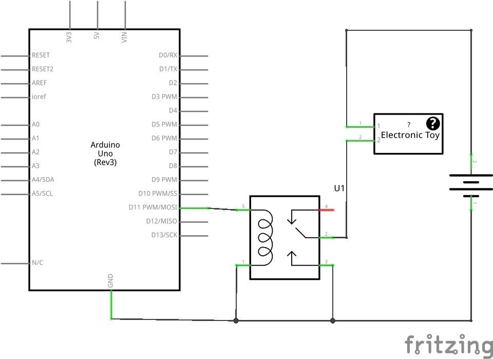
Attach your protosnap mini onto a bread board. Attach a relay onto the bread board and get four jumper wires as well as aligator clips. On the electrical component of the card you will need to connect the aligator clips so that they are connected to the GND as well as the lever(The GND will be located below the latch). Connect the jumper wires to the aligator clips and put them onto the outer points of the relay.
Step 6 Connect!
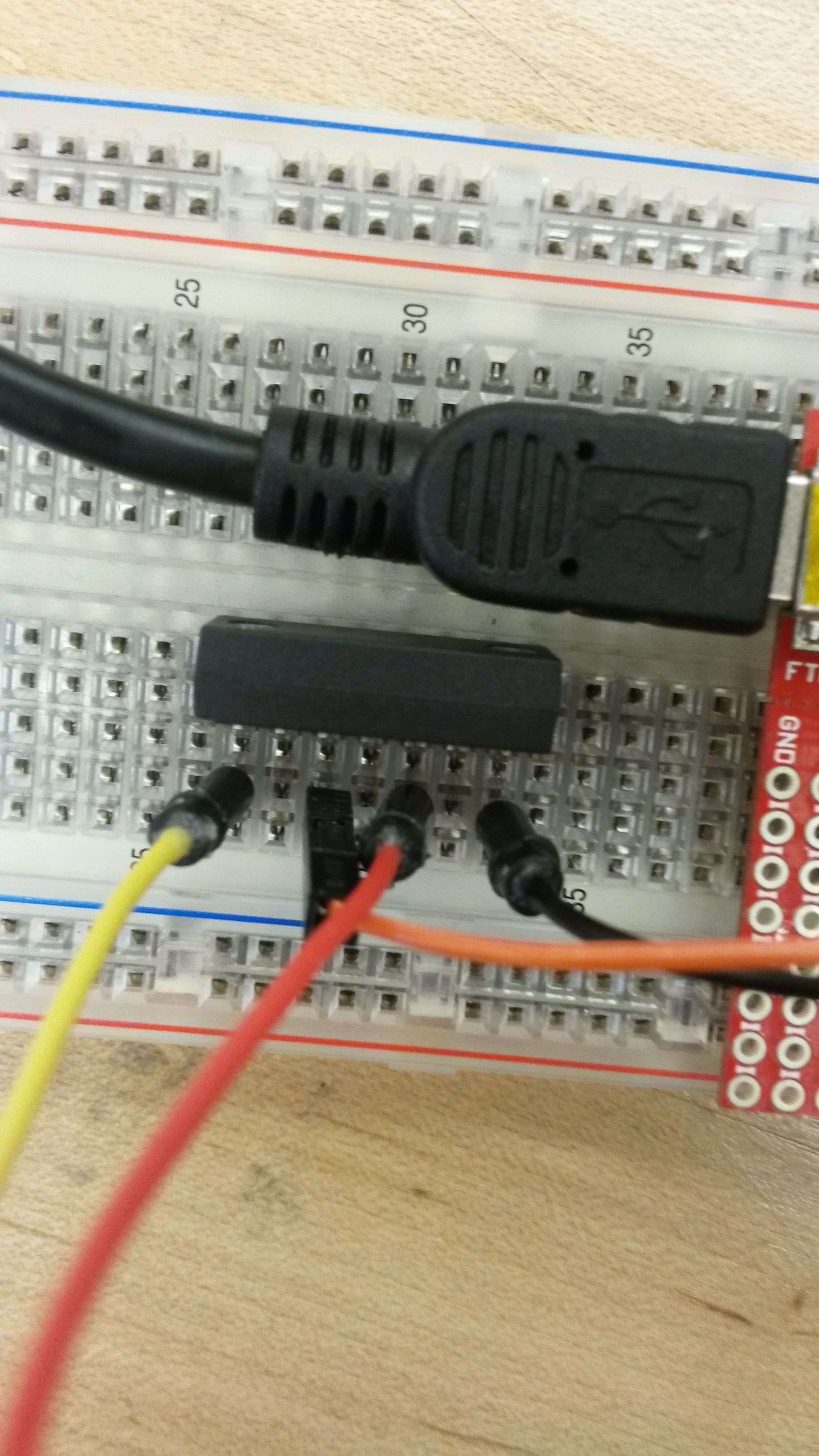
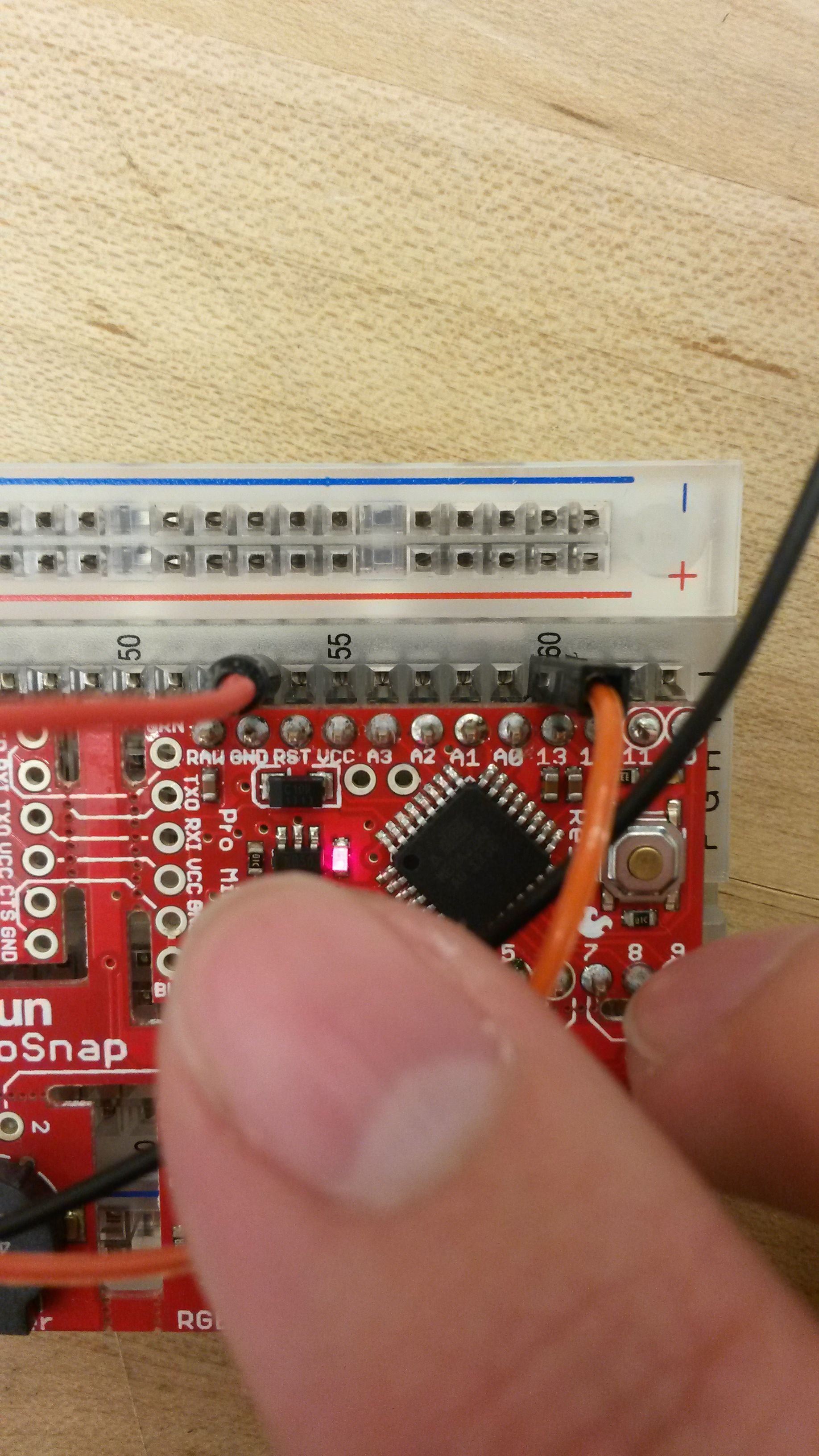
Once you have connected the electrical component of the card onto the relay now use two jumper wires to connect to GND and a Pin on your protosnap. Your jumper wires will be connected to the two center points of the relay. You can choose any pin you please we will be using this pin in our sketch
Upload Sketch to Arduino
Now that you have hooked everything up it's time to write a sketch to make the sound come out. Let's write a sketch where you can use sensor value to control when to turn on the sound.
Try this Sketch in Arduino
Click here for link to the sketch