Hacked Digital Vernier Caliper Using Arduino
by Ahmed_Ragab in Circuits > Arduino
11552 Views, 17 Favorites, 0 Comments
Hacked Digital Vernier Caliper Using Arduino
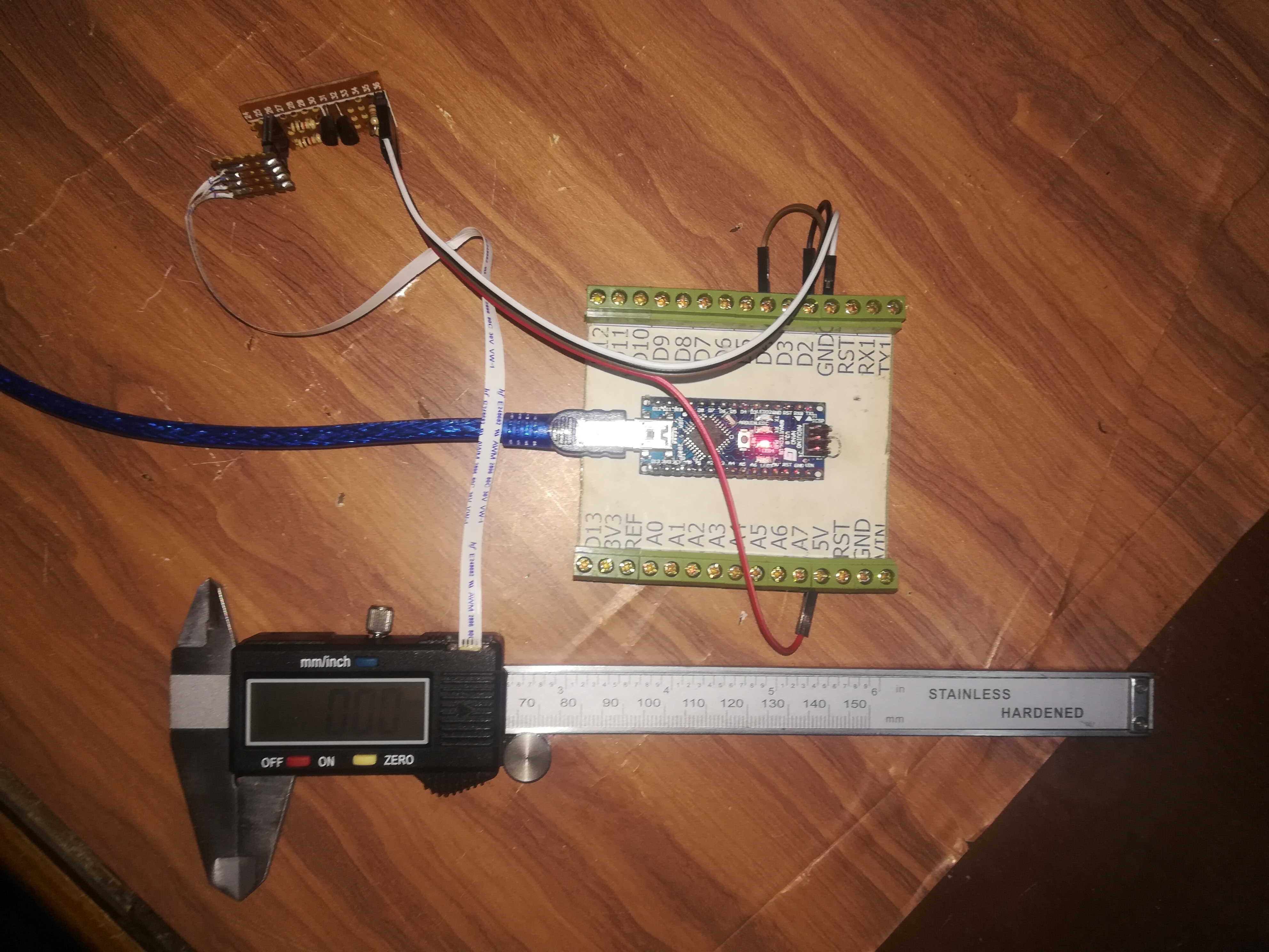
So, what about doing some measurements with your Digital Vernier Caliper and having your Arduino to do some work with these measurements ?
Maybe Saving them, Doing some based-on calculations or adding these measurements to a feedback loop from your mechanical device.
In this instructable we're going to disassemble a Digital Vernier Caliper, hook some wires to it and interface the Caliper with the Arduino to display its measured values on the Arduino Serial Monitor.
How It Can Be Done
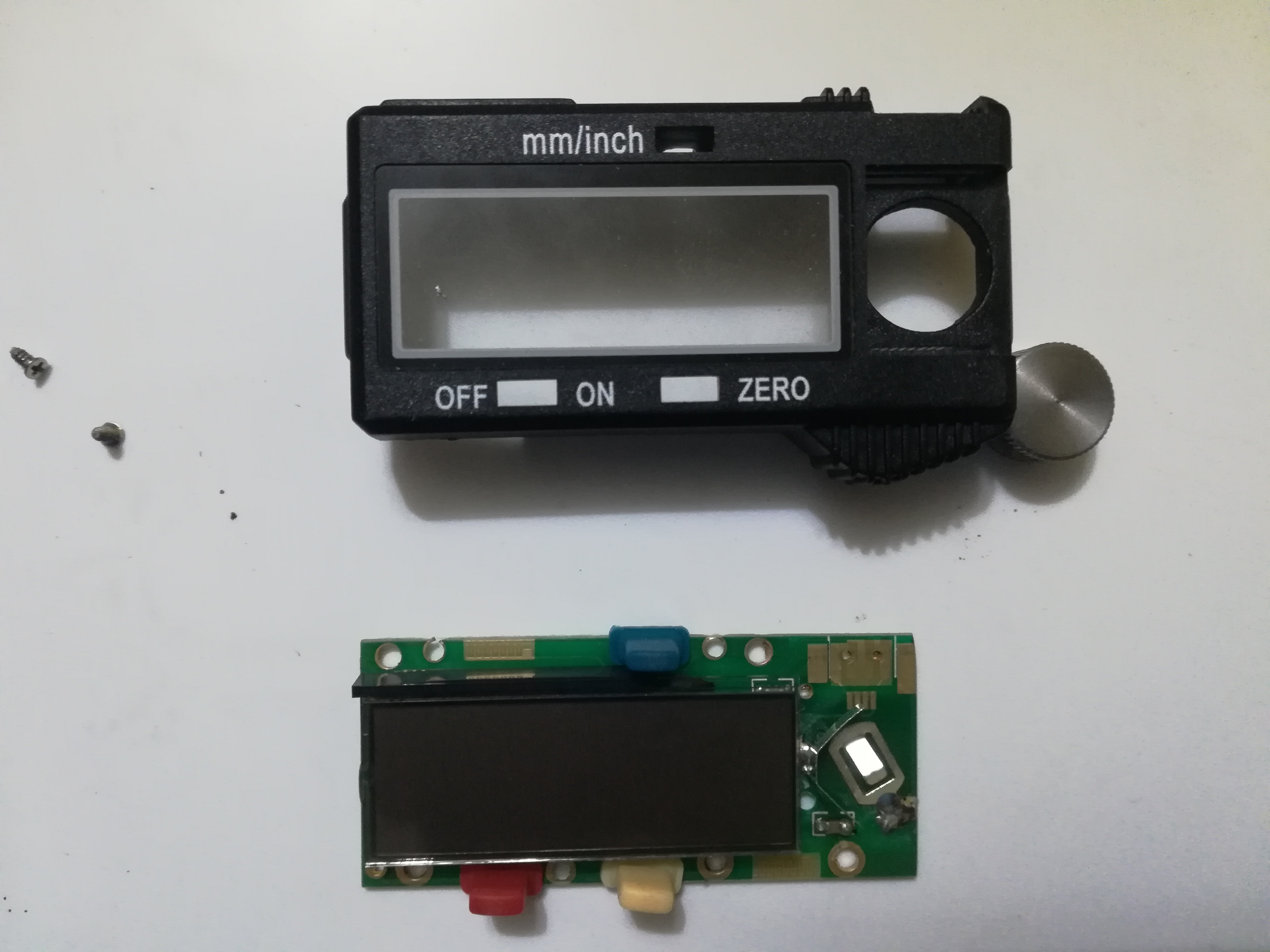
It turns out that some digital calipers are capable of transmitting the measured data appearing on their displays using different protocols to be used by other devices.
Actually THERE IS a place for an interface socket on the caliper board, but nothing is soldered on it.
You can just slip out the upper cover in the display (not the battery cover) and you'll find 4 pads that are supposed to have a socket on them to communicate with the caliper, But they aren't :( .
This fact was discovered many years ago on different Calipers and this instructable is focusing on the exact model of the Chinese digital vernier caliper you can see in the pictures, So please make sure that yours is the same model as different model may have different protocols to work with, Therefore different codes to use, But the main idea is the same among most of these Chinese ones.
We're going to:
- Disassemble the Caliper
- Find Where we can solder an interface socket to the board
- Identify Connector's pin-out
- Solder it and assemble the Caliper
- Reverse engineer the transmitted data to know how its protocol works
- Level shift the Caliper signals to suit the Arduino
- Upload the code and that's it :)
What you'll need:
- A Digital Vernier Caliper
- Arduino (Any type will do the job)
- Logic Converter Board (I'll attach a schematic for one)
- A Fine clean tip soldering iron
- Thin soldering wire
- Some jumper wires
Disassemble the Caliper
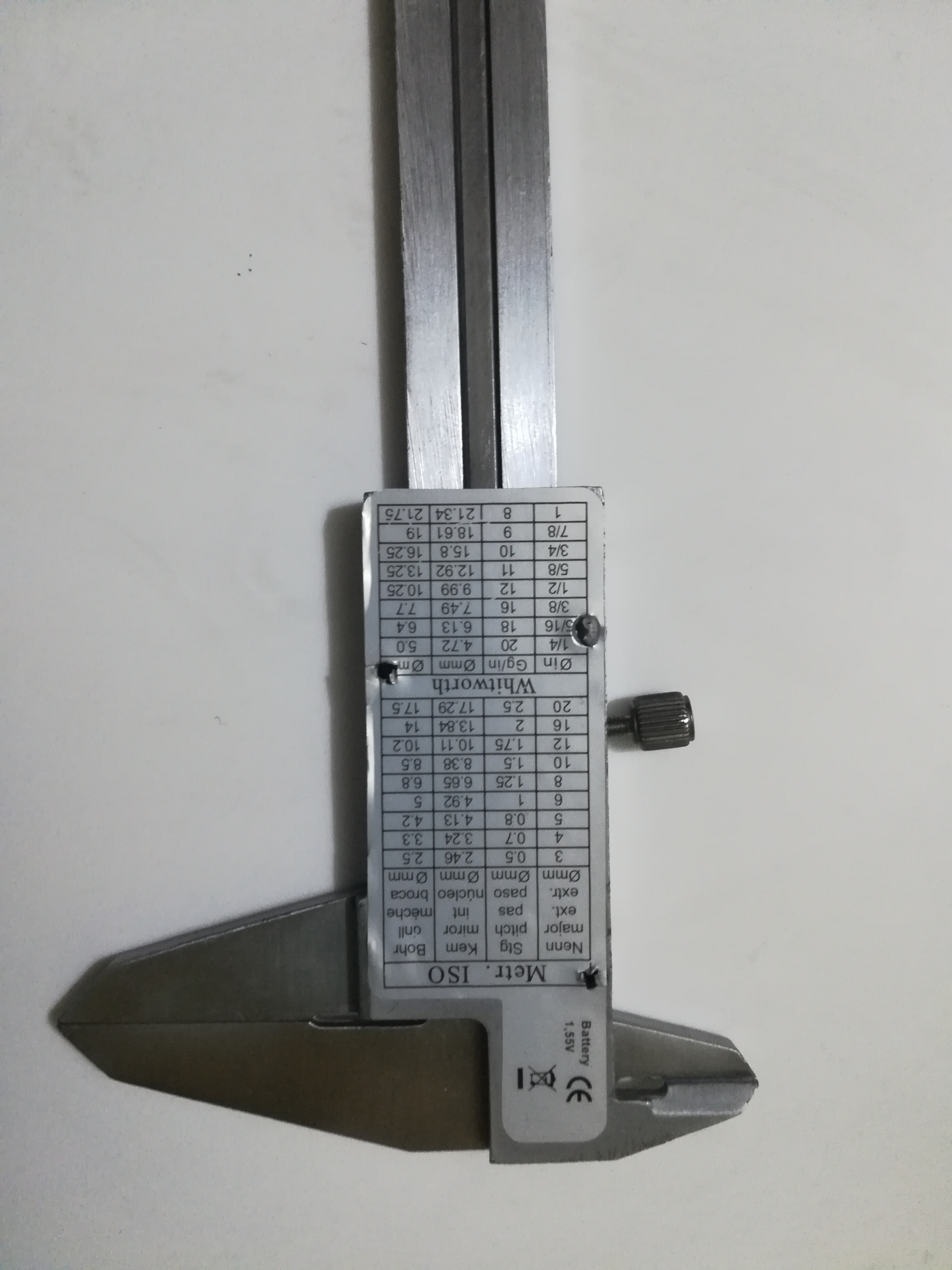
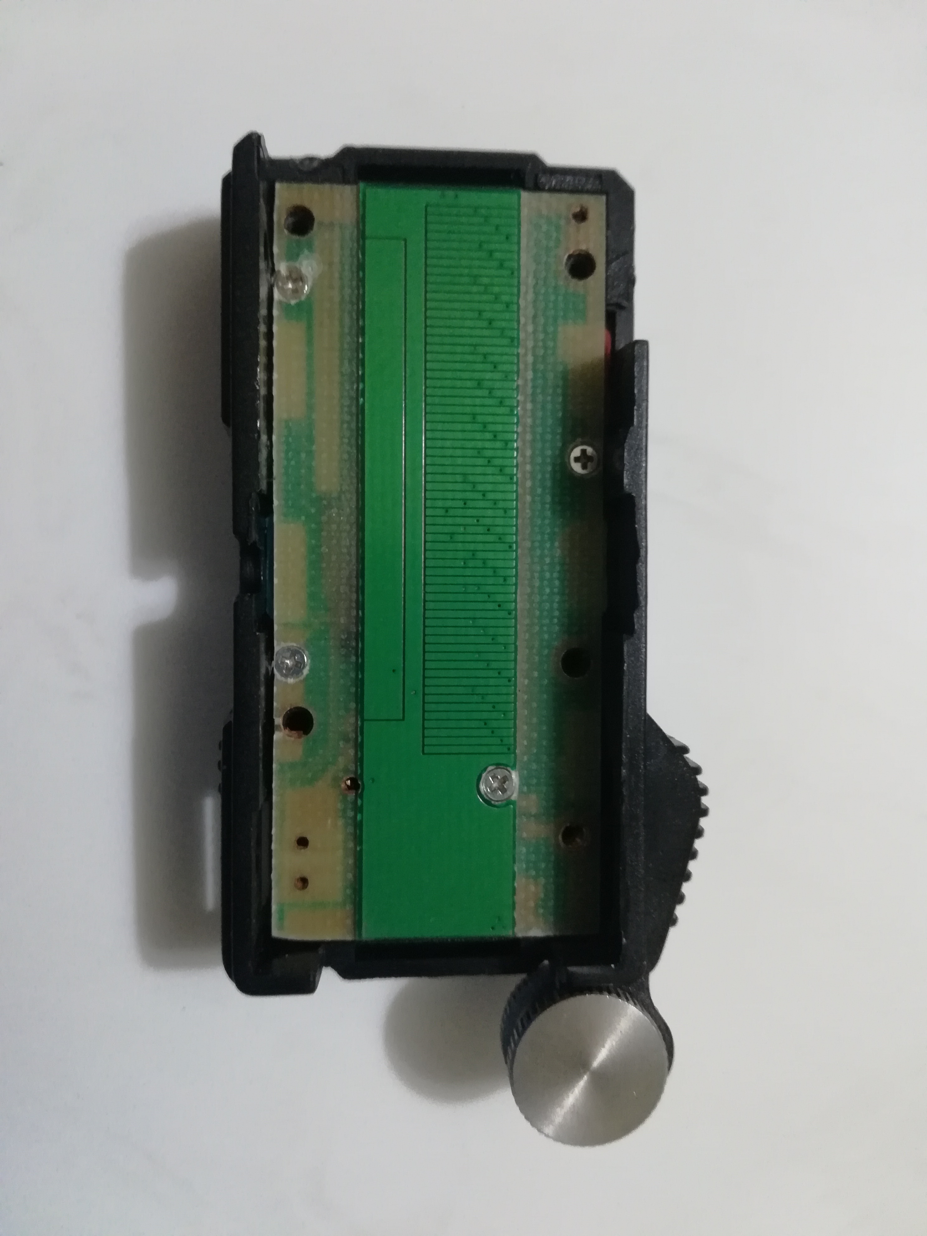
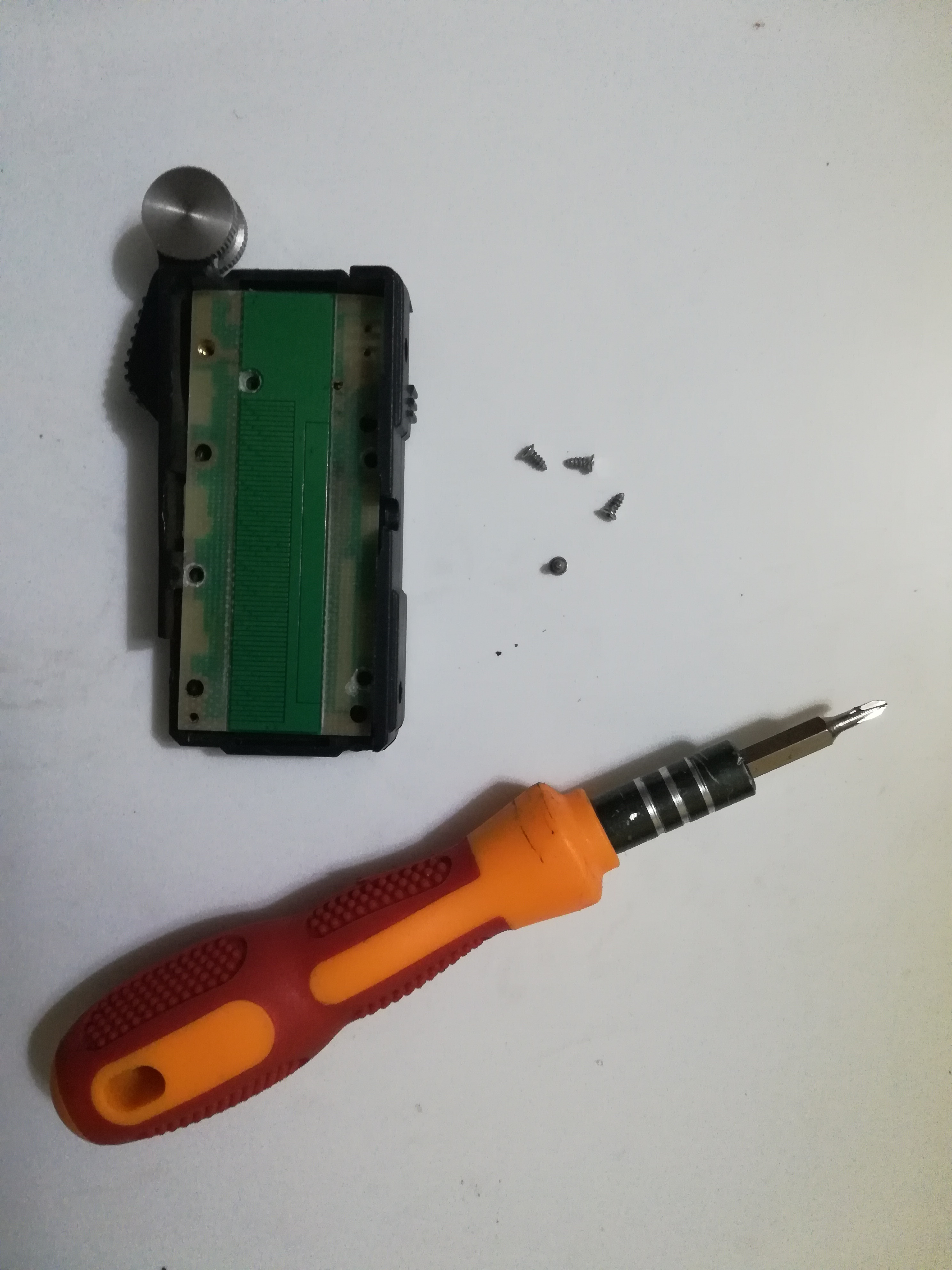
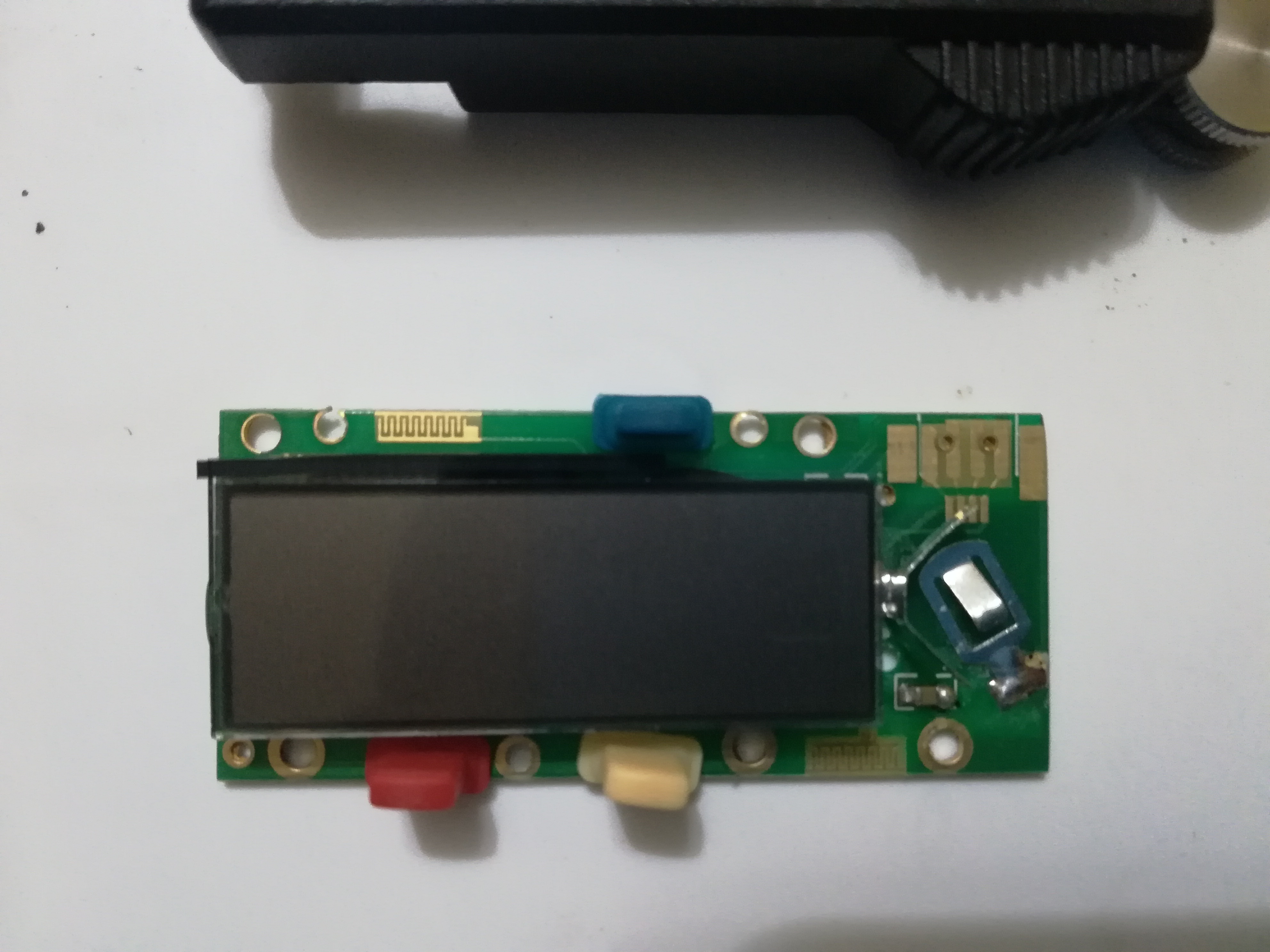
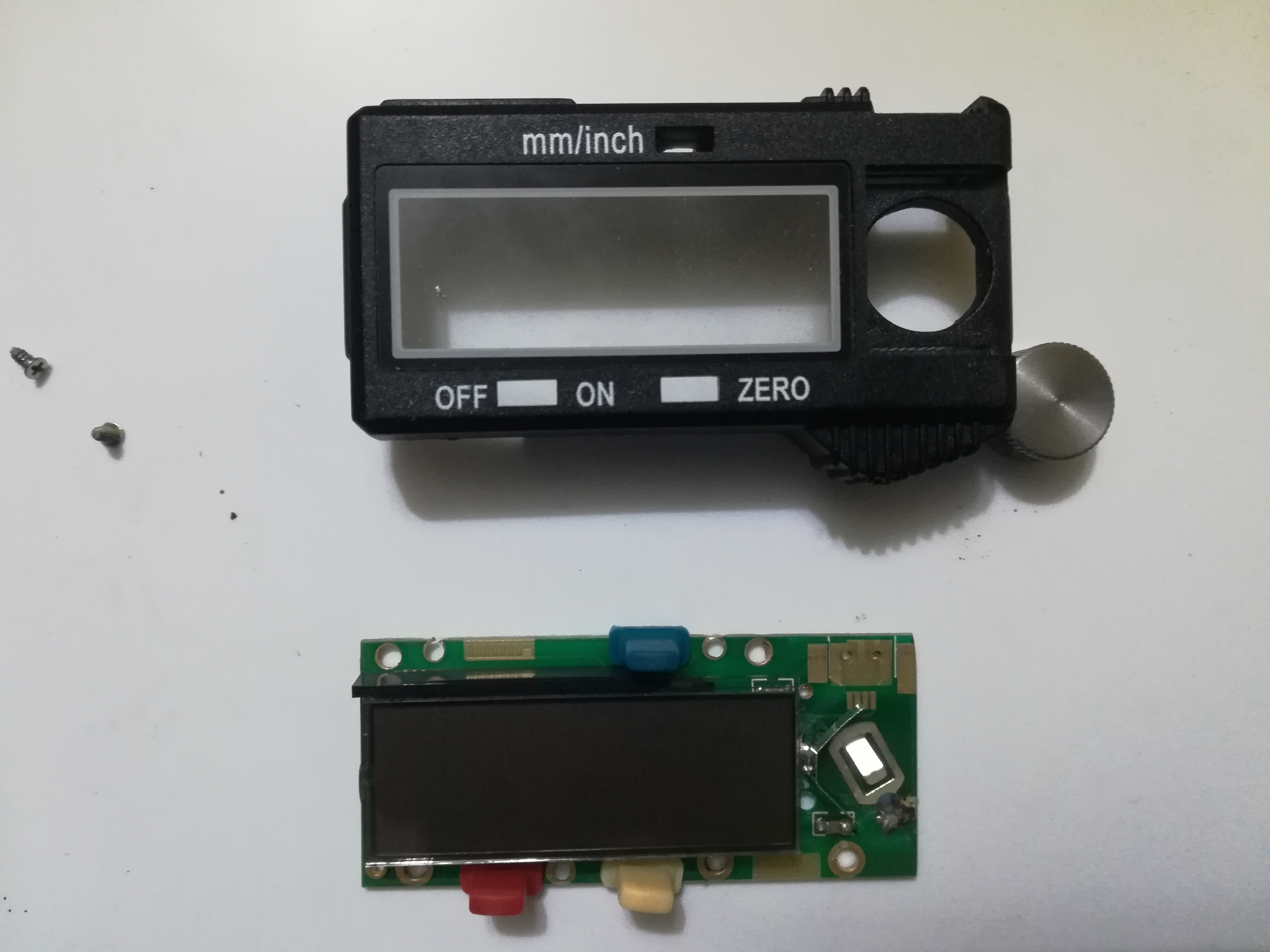
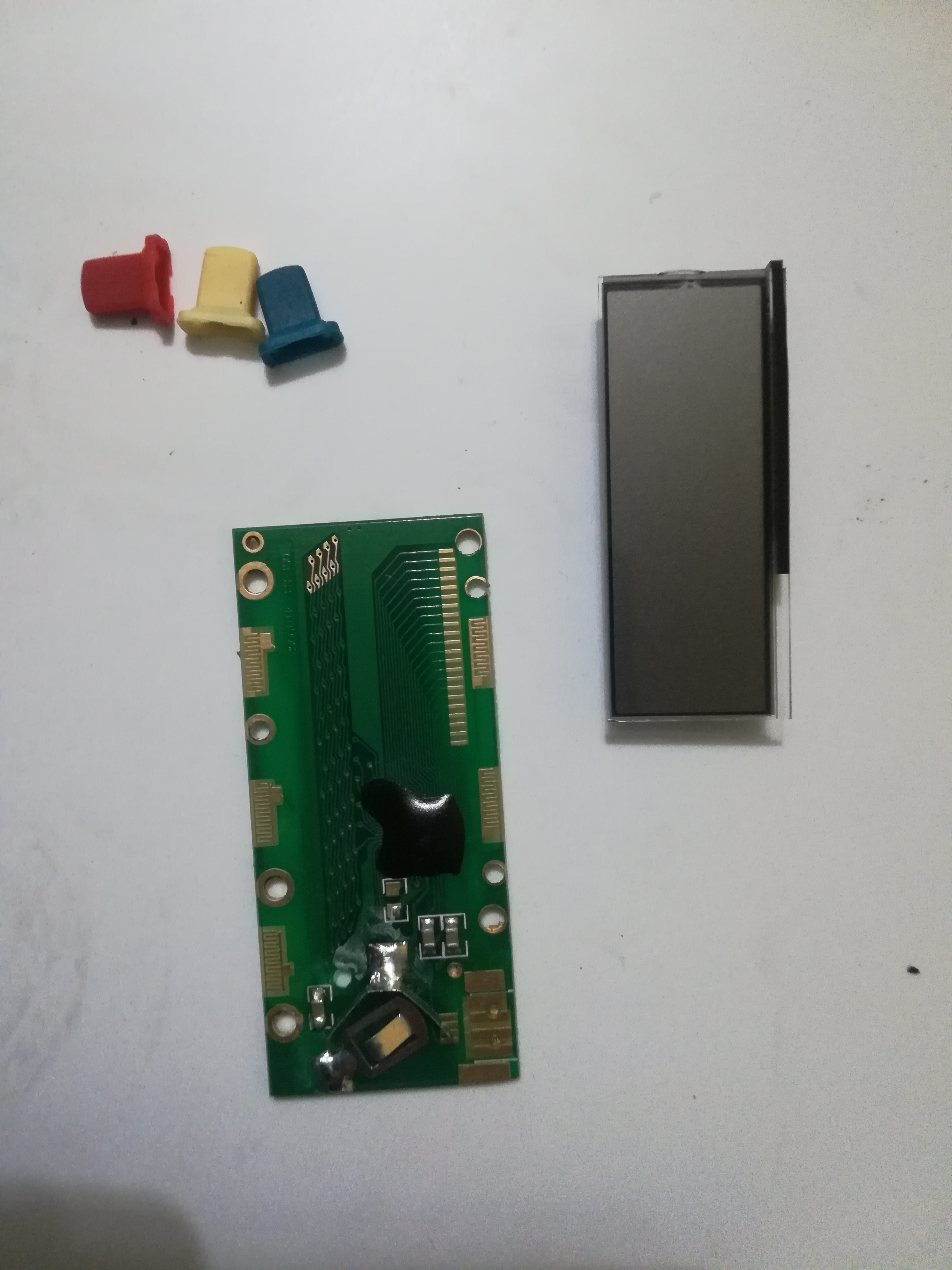
- First of all Remove the Caliper battery from its clip.
- For this model you will find a silver guide paper on its back and you will find four mounting screws beneath it. They are holding the case together and we need to unscrew them using a Philips screw driver. You can just walk your screw driver over the paper on the sides and you'll spot their mounting holes.
- After that you'll see that the PCB is mounted to the front panel with four screws, You need to gently unscrew them using a fine tip Philips screw driver.
Be careful not to scratch or cut any of the traces on both of the PCB sides.
- Now after getting all the screws out and putting them in a safe place were they can't be lost :),
- You need to lift the PCB Carefully as the display and the three rubber buttons may fall apart.
- At this point you can pull the display and the buttons from the PCB and put them with the screws and continue your work with the bare PCB.
Find the Needed Pads to Solder the Socket
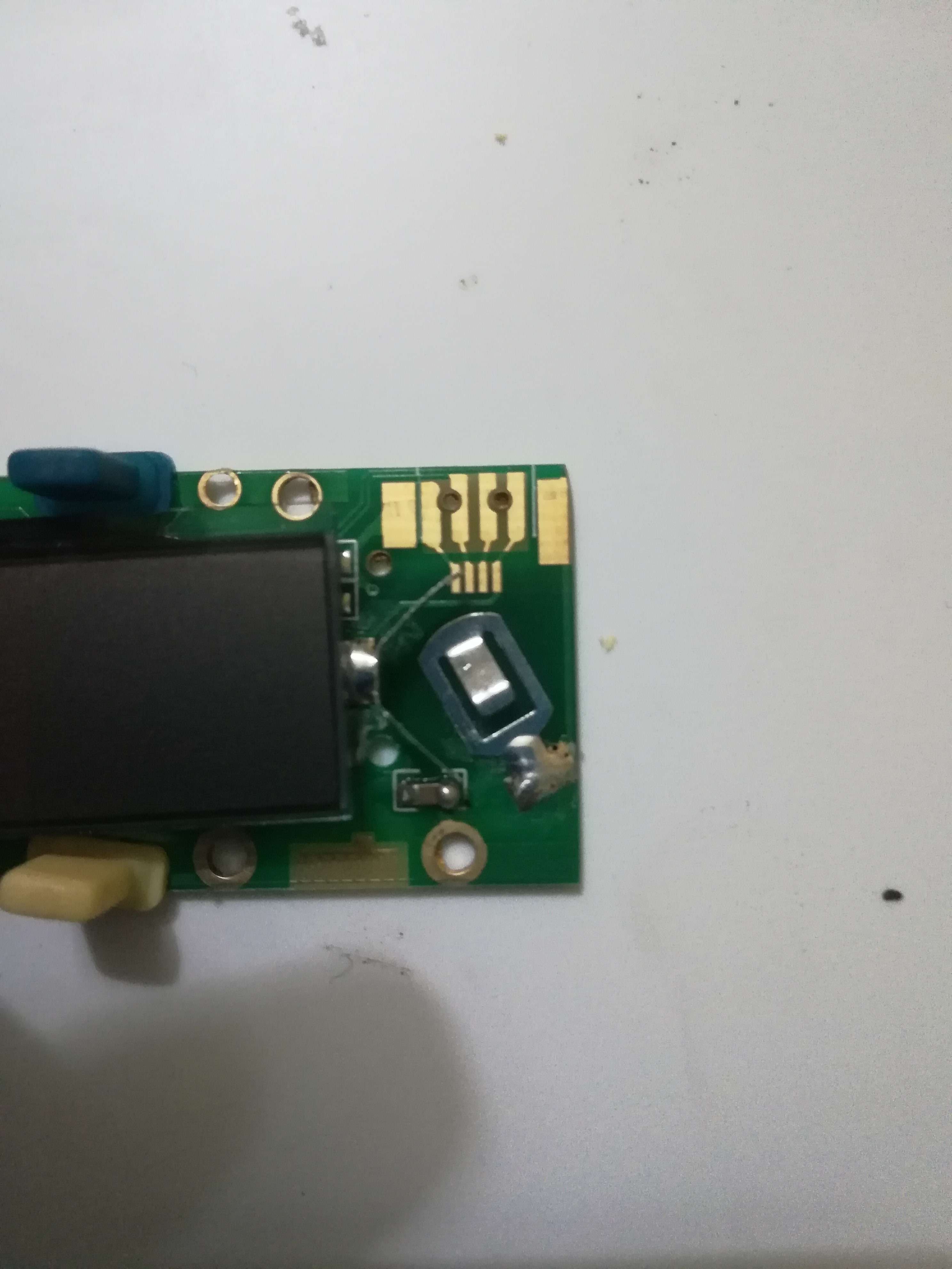
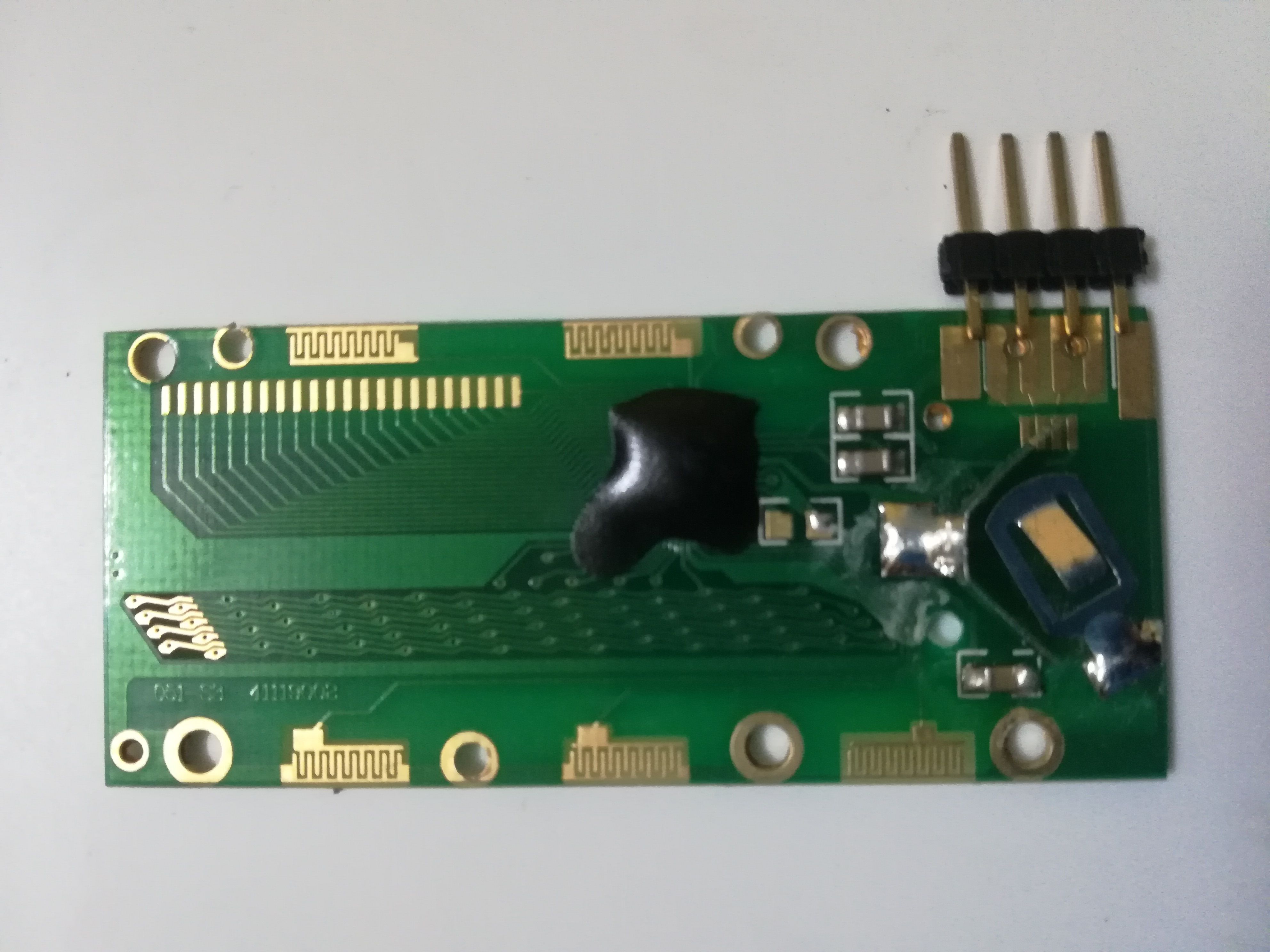
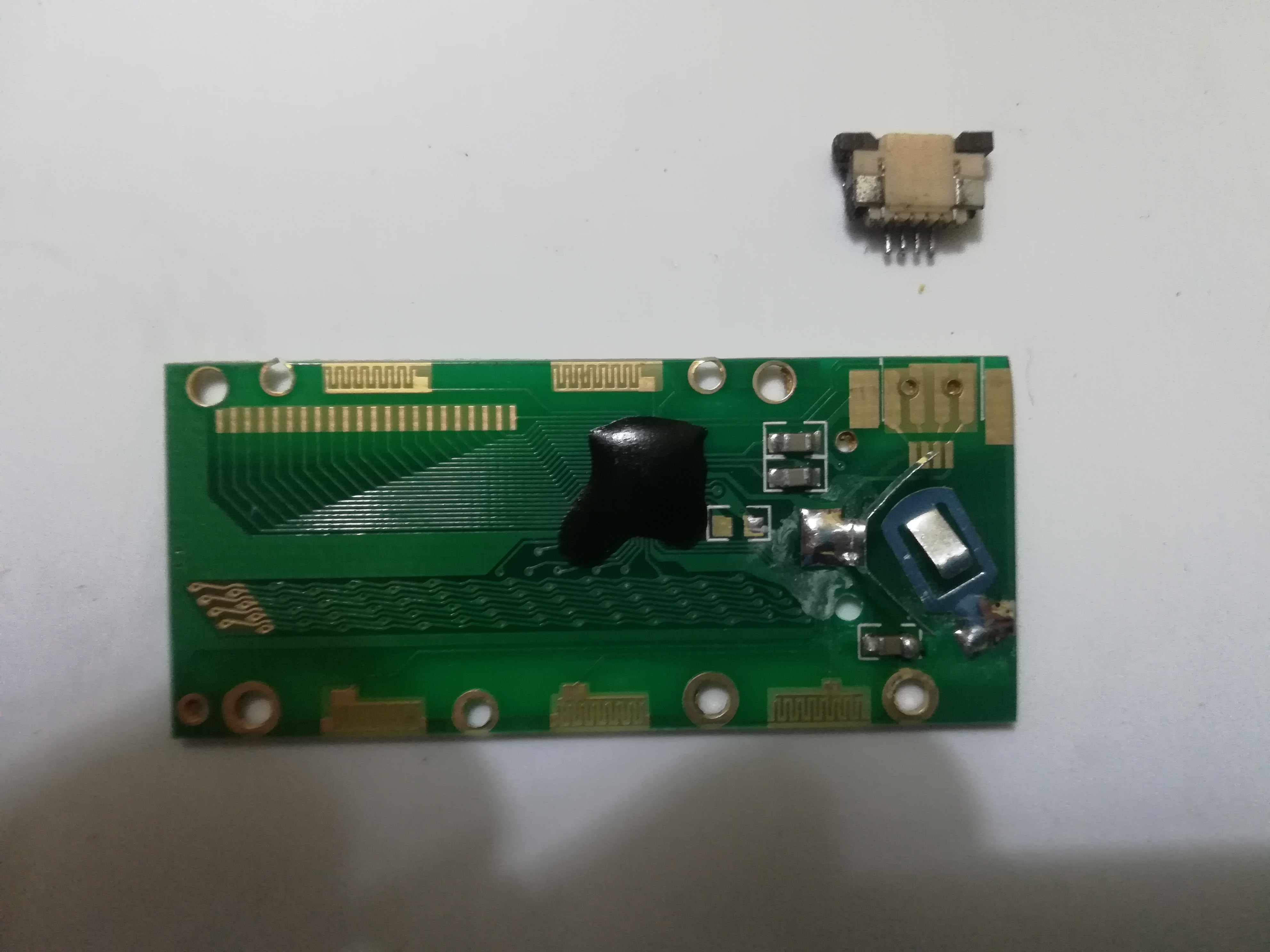
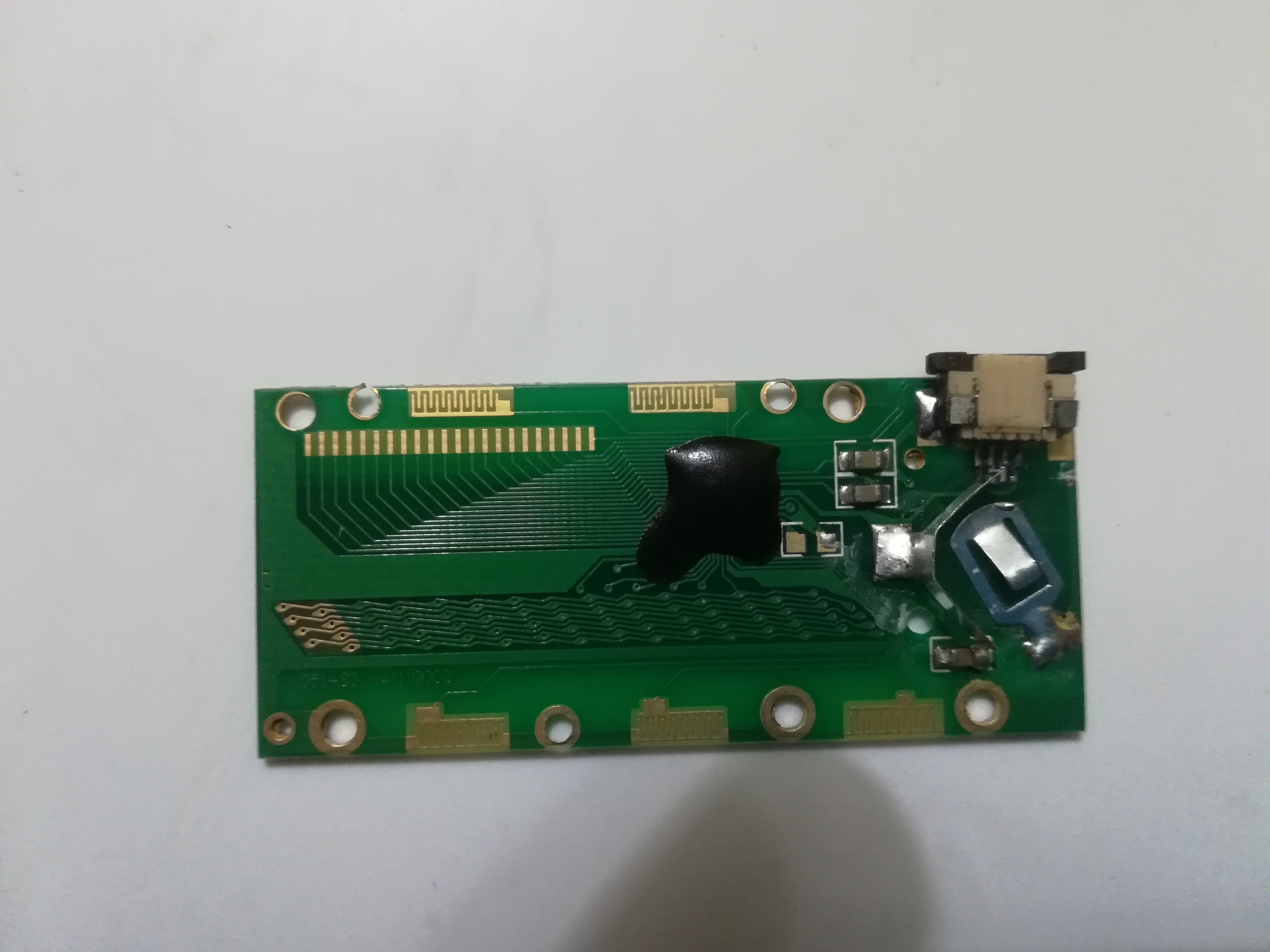
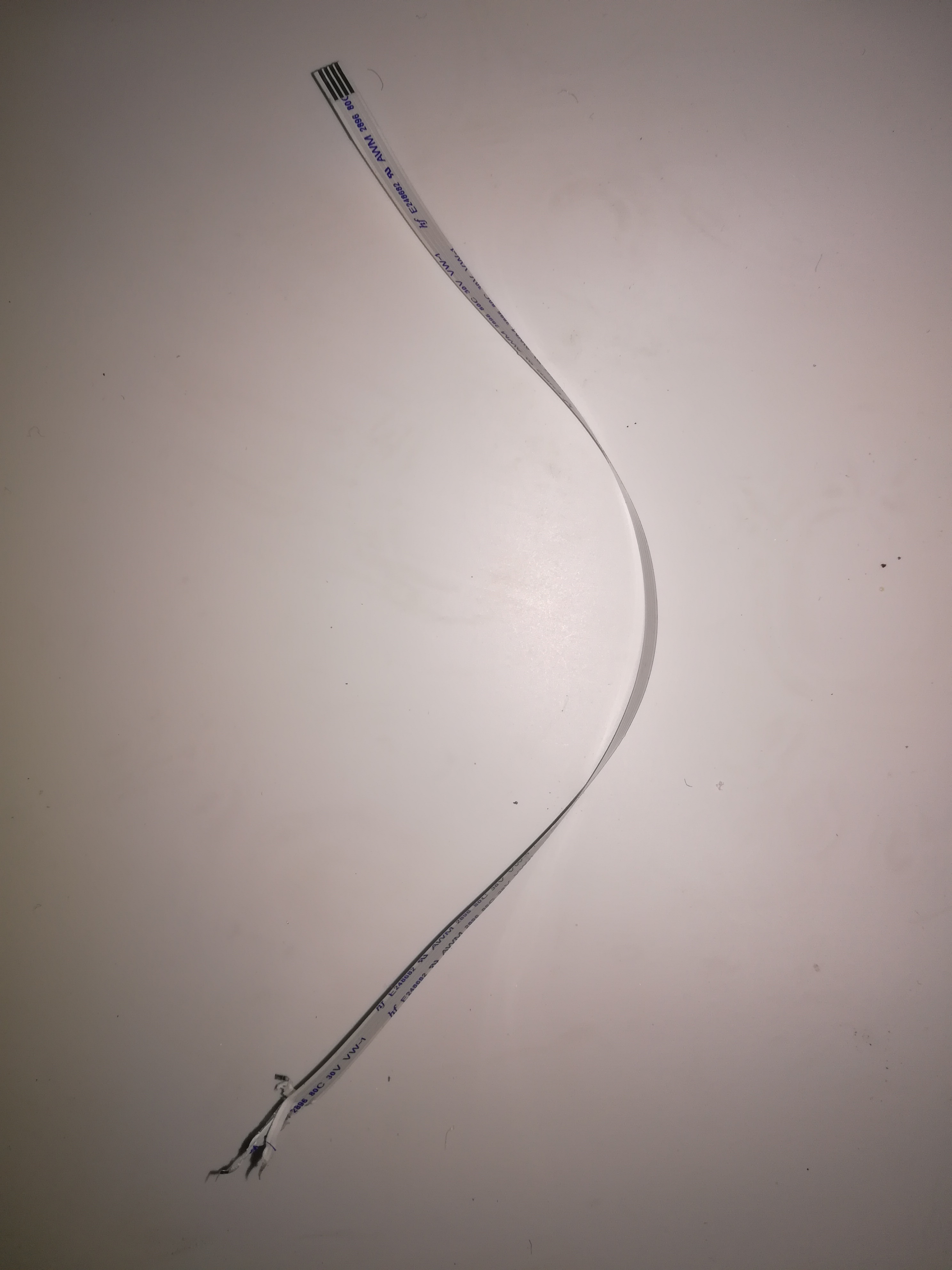
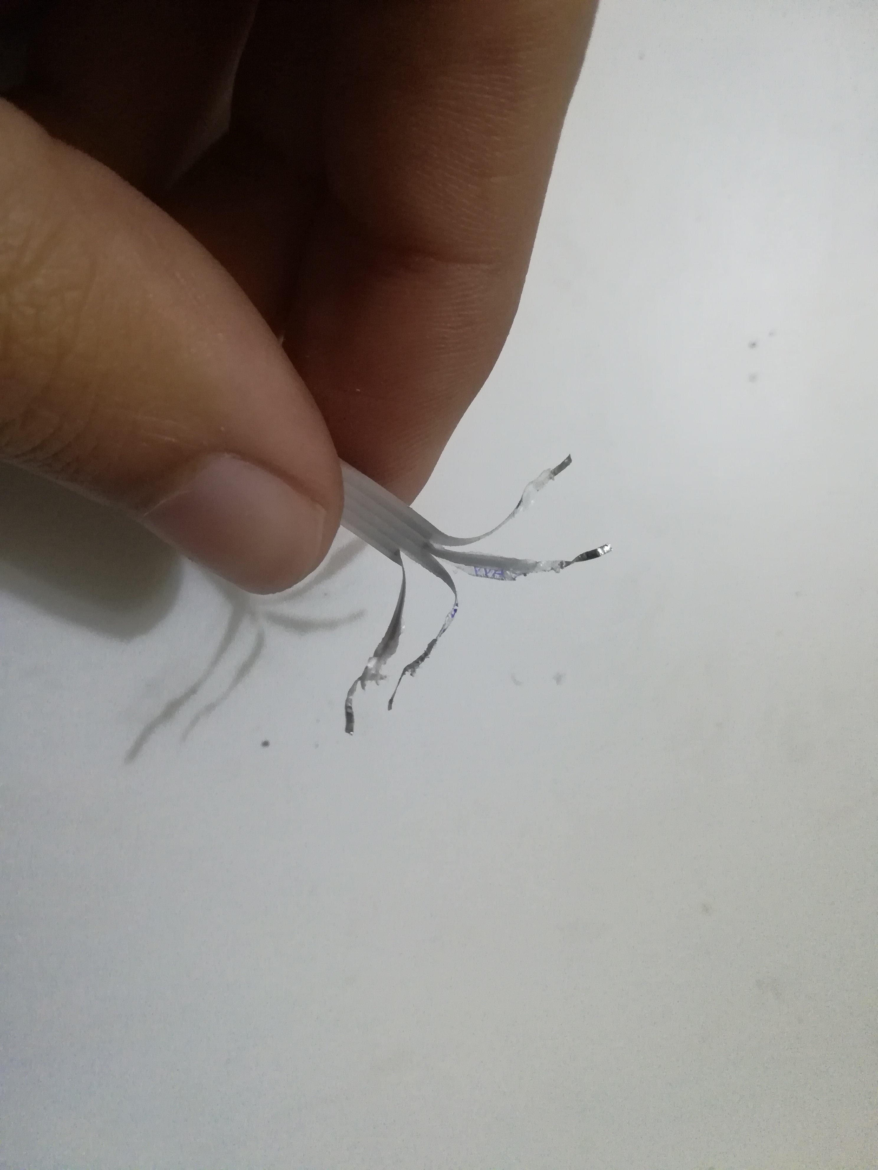
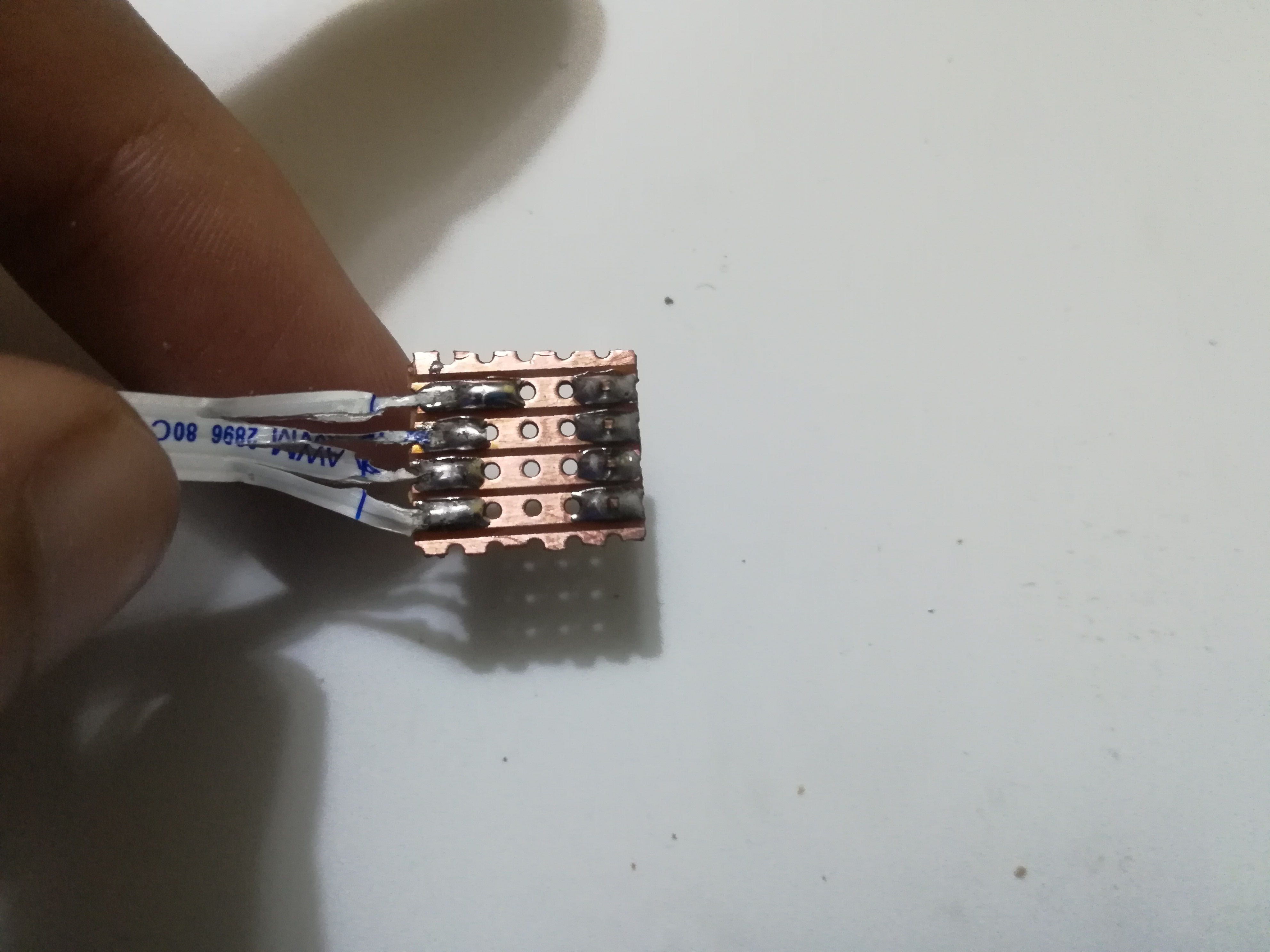
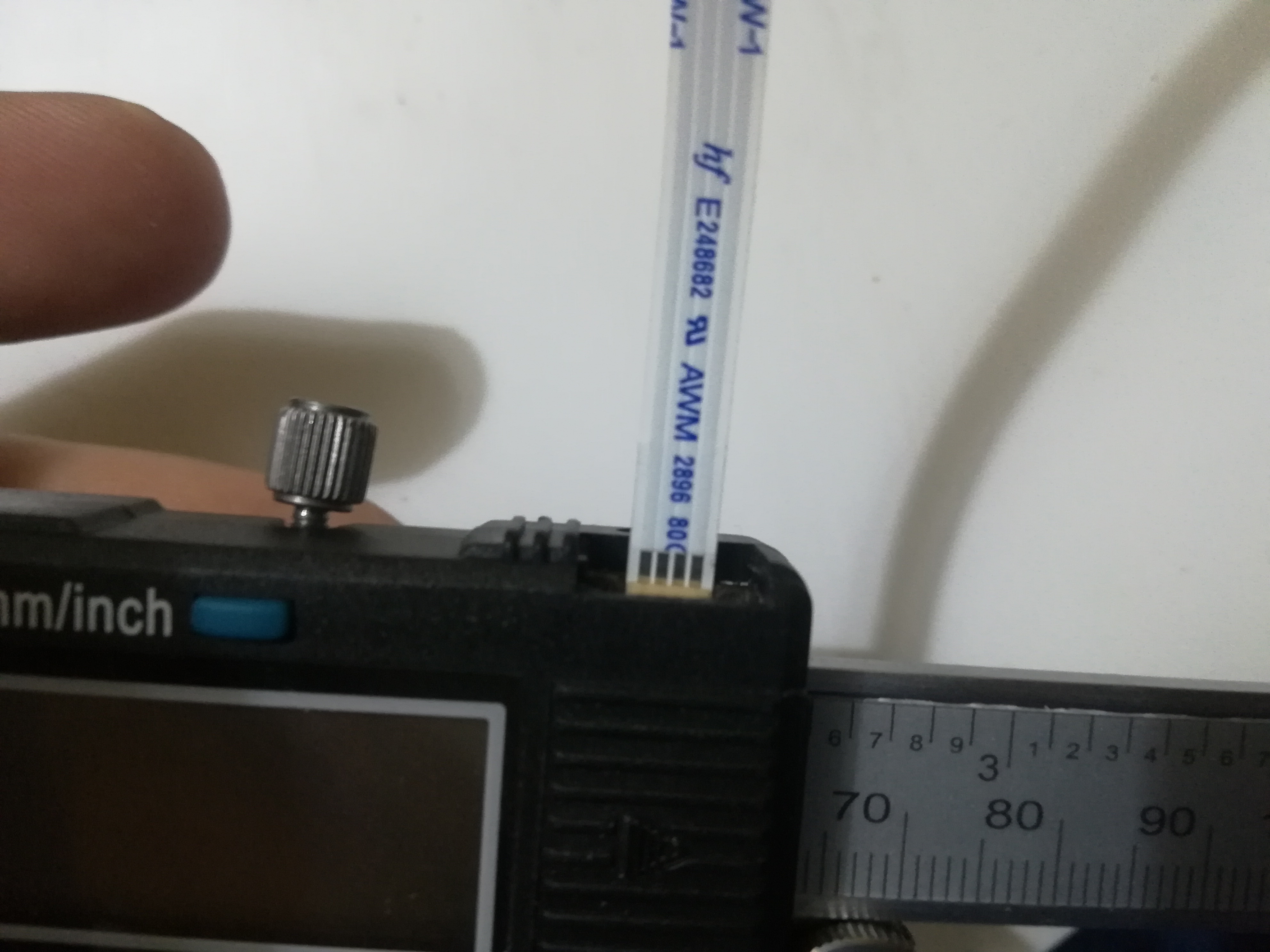
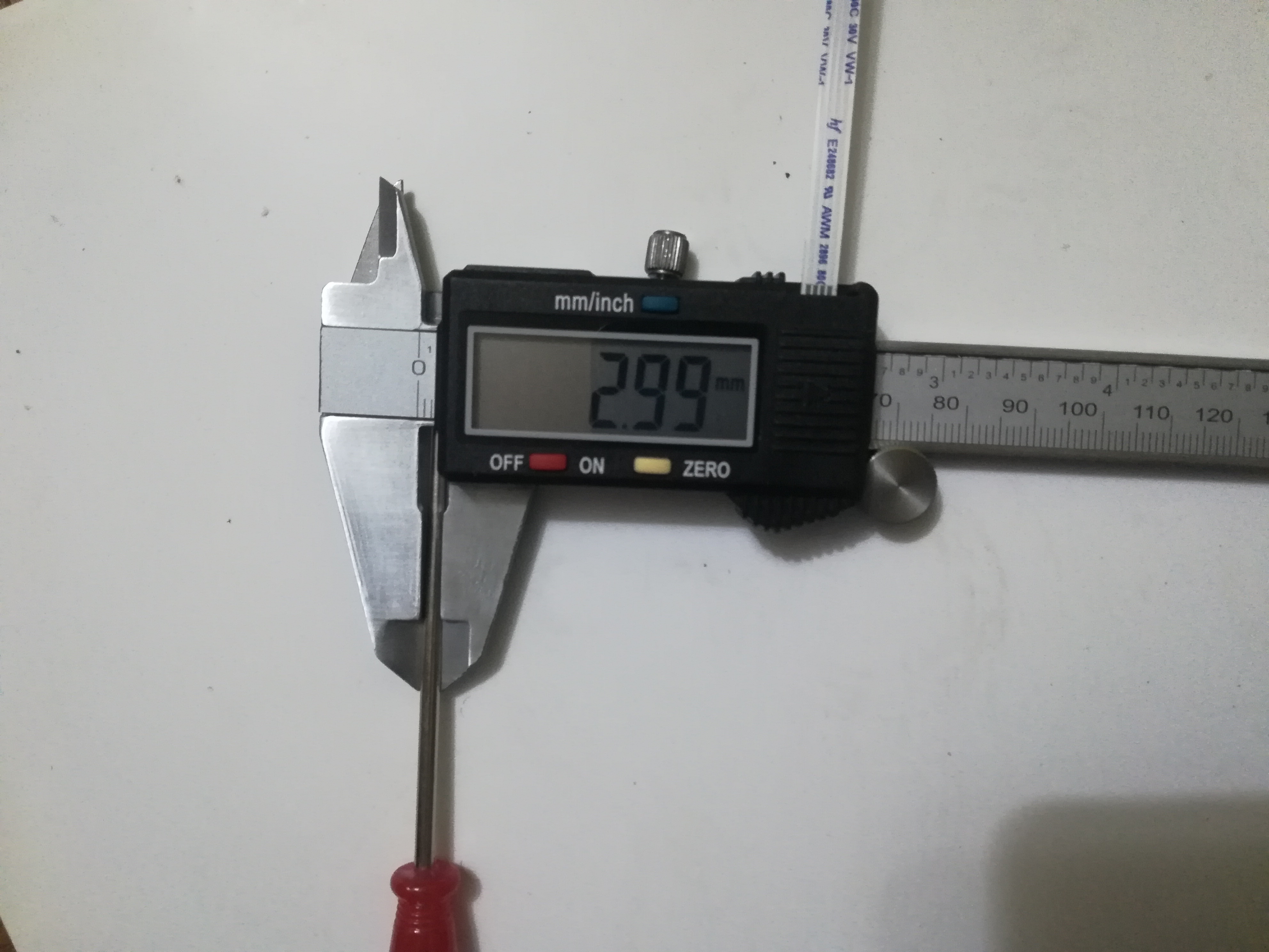
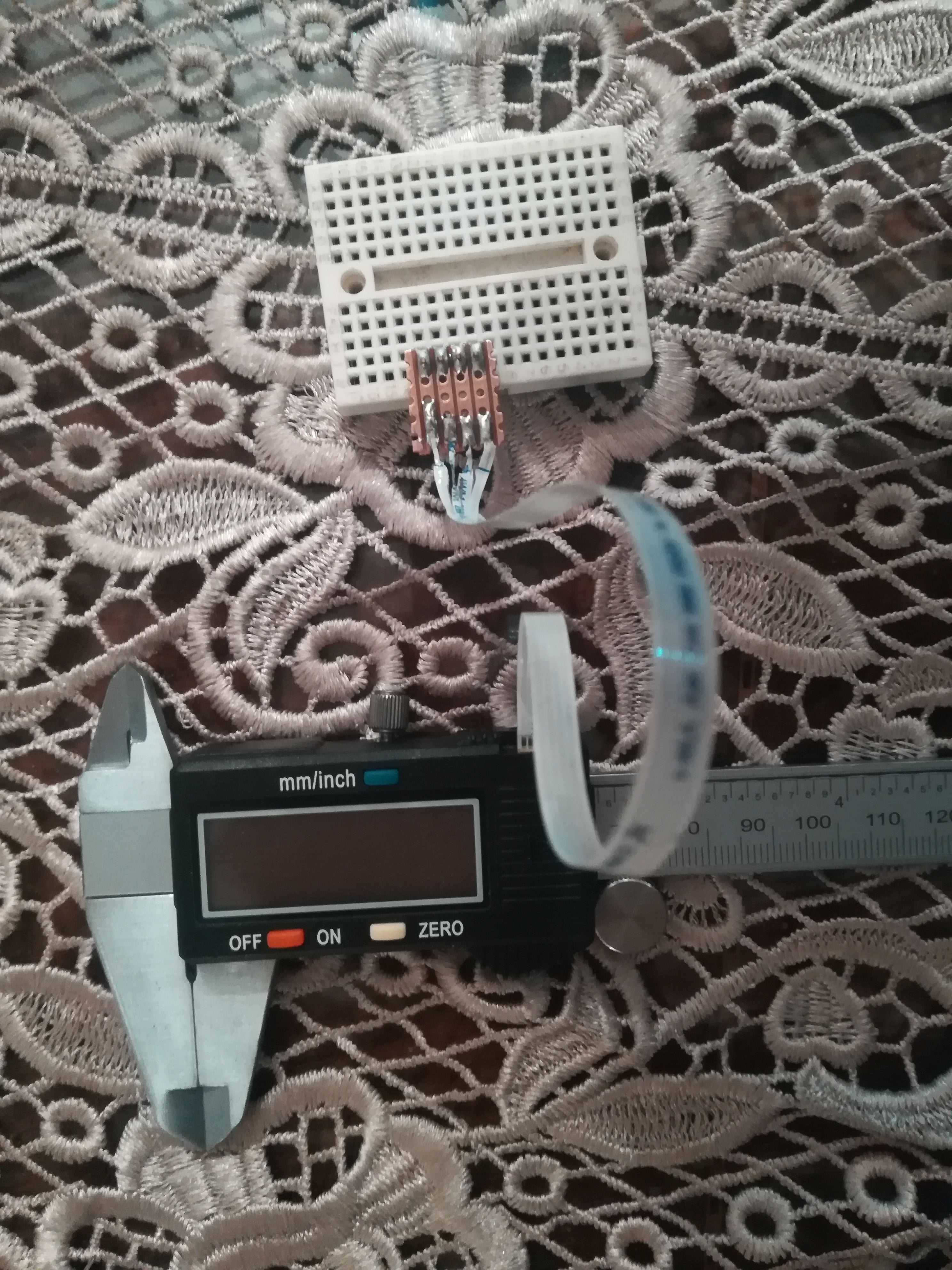
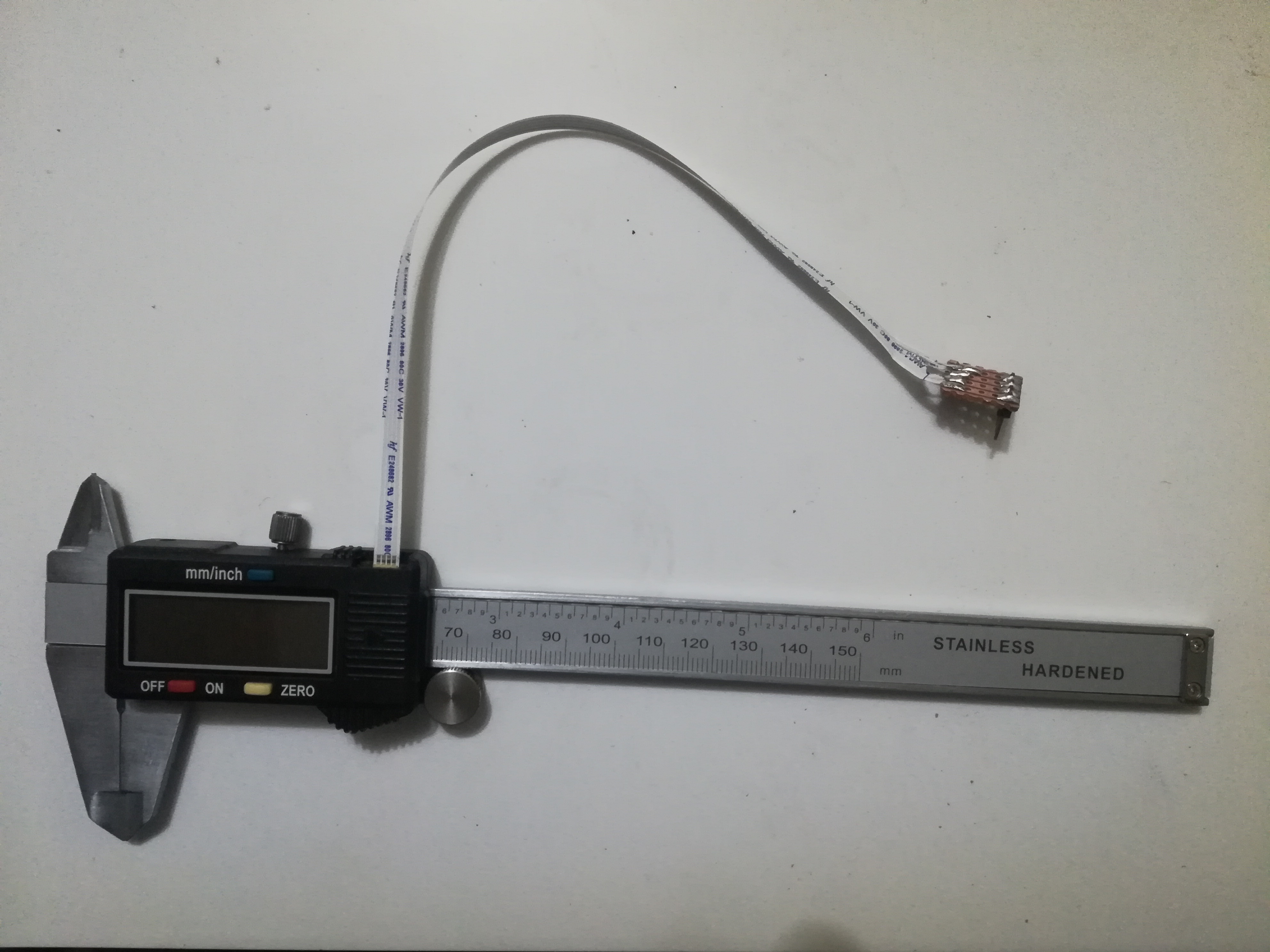
Now, when you look at the top side of the PCB you can easily spot where the data connector should be mounted.
You can also see that Generic pin headers can't be soldered without much of tweaking as the pitch of connector is smaller than theirs (pitch : distance between the centers of two adjacent pads on the connector)
Pin headers pitch is 100 mil or 2.54 mm so you can either slightly bend them and get them soldered, Or you can find another socket.
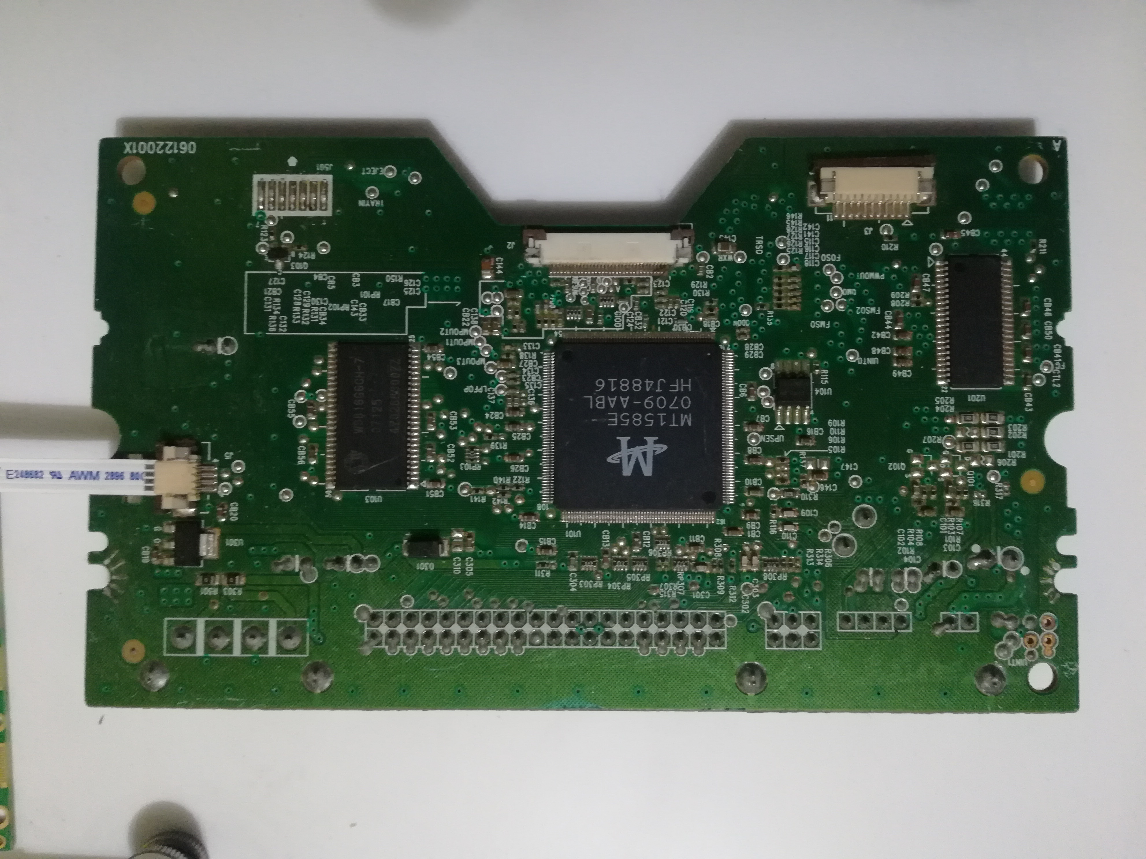
And here is when my full box of just sitting around PCBs came to a good use.
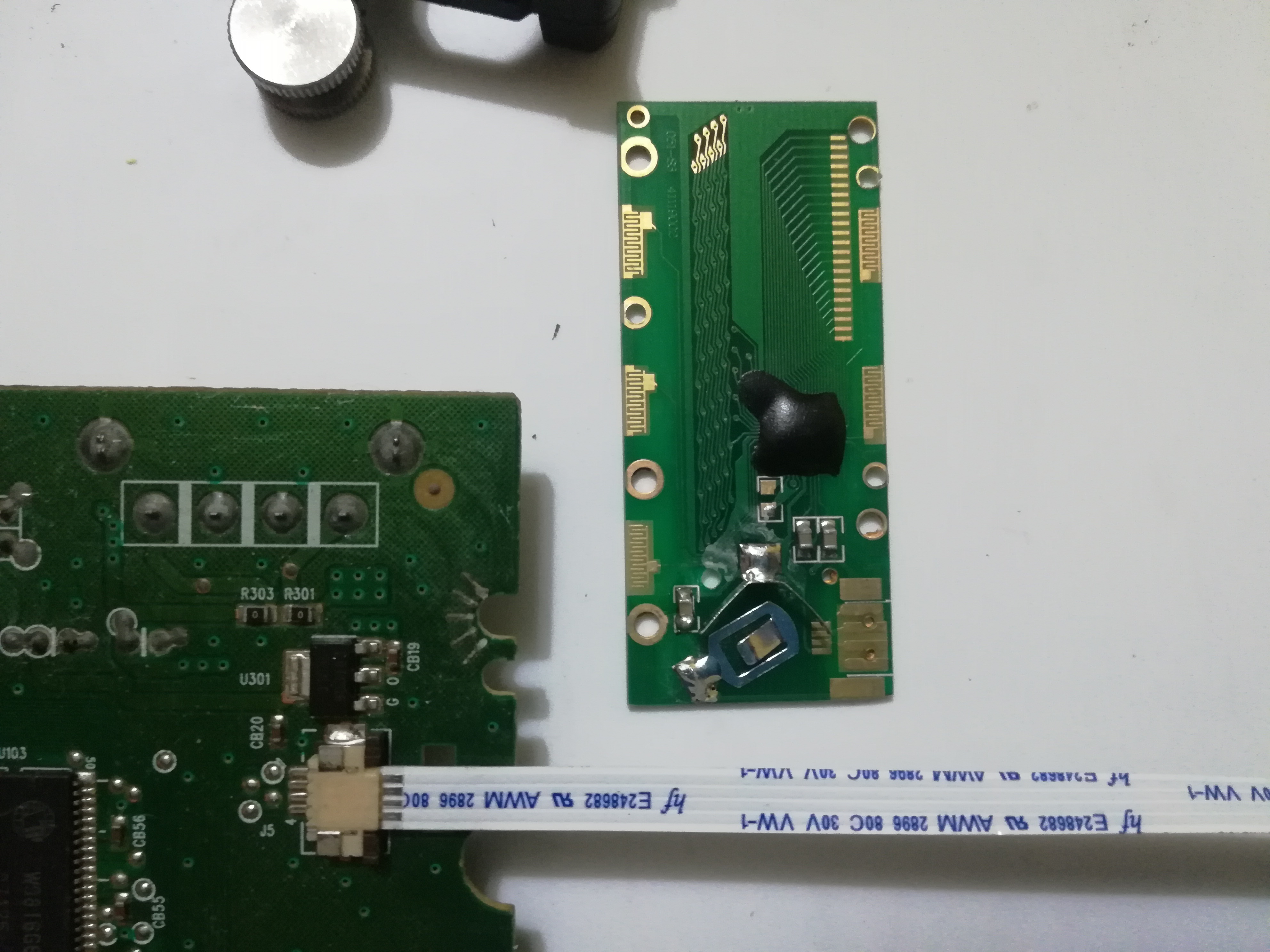
I found a perfect 4 pin flex cable connector (FPC connector) on one of the old CD-ROM drive PCBs and decided to use it with the Caliper.
No need to say that you should be careful while desoldering PCB connectors as their plastic casing may melt.
Be careful also that either you chose to use pin headers or a special socket as a connector that you need this connector to be able to mechanically fit in the opening for the connector in the Caliper display case. (You can see the picture for more clarification)
Identify Connector's Pin-out
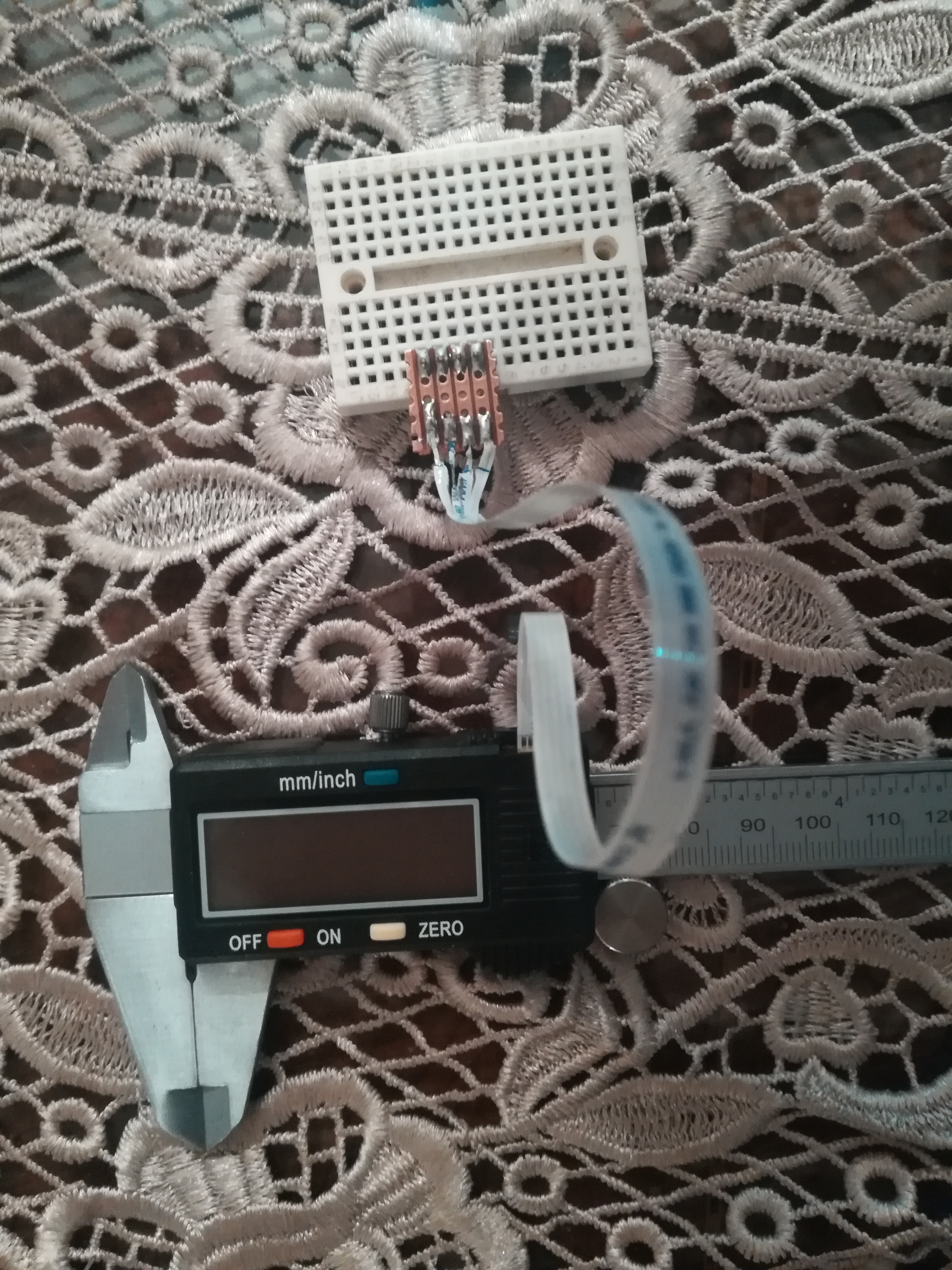
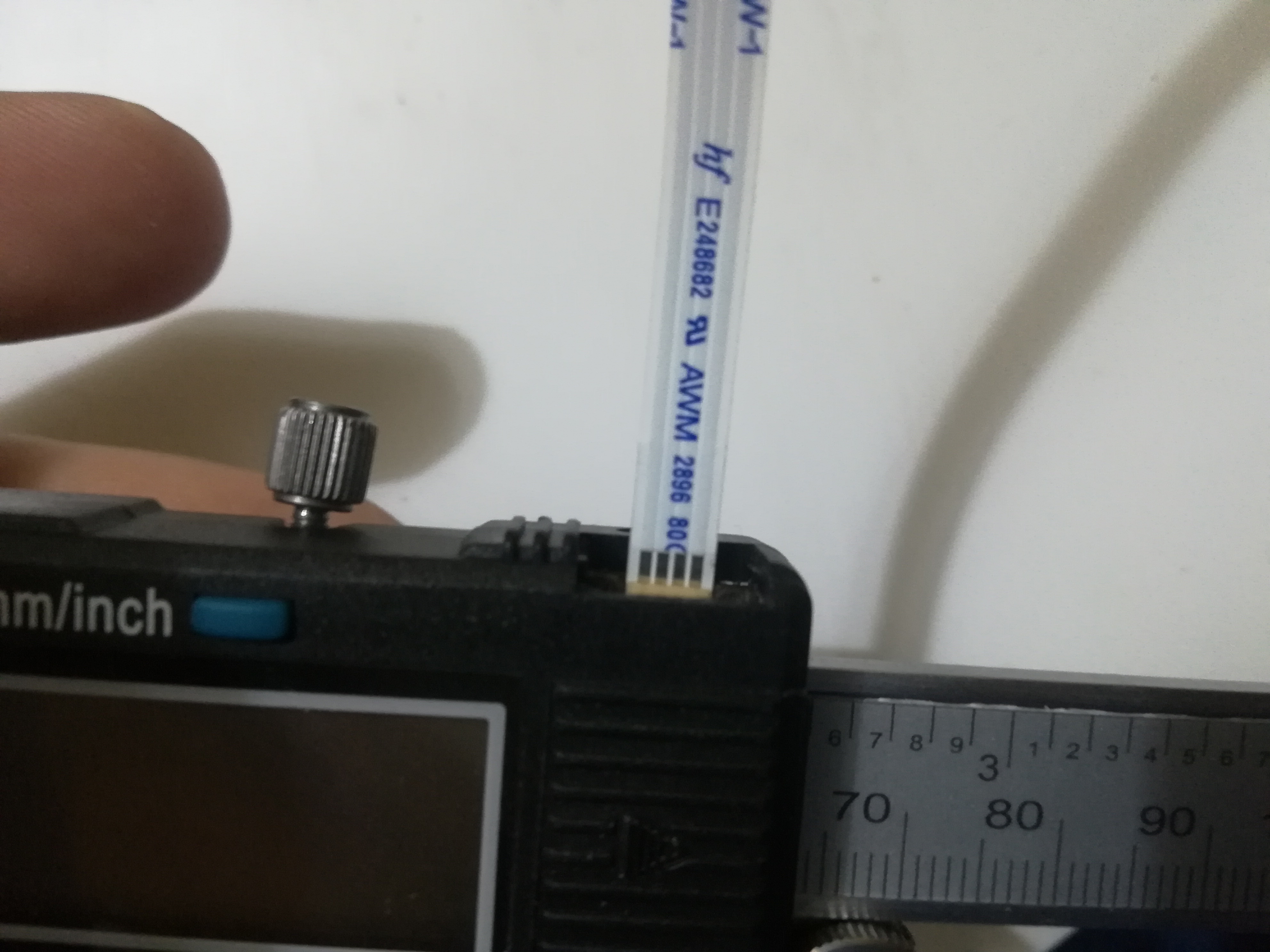
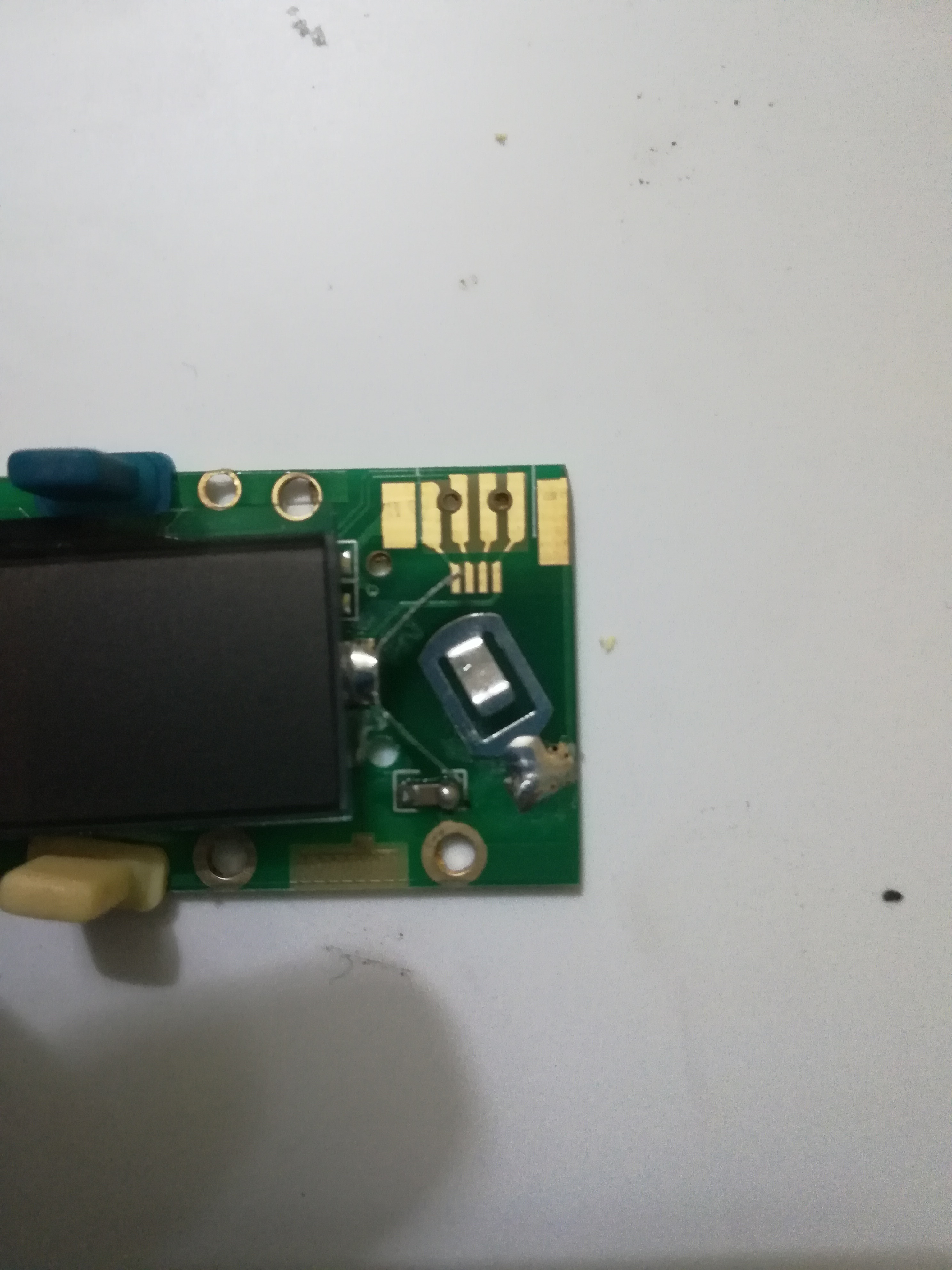
Now after finding the needed pads, we need to know what each pad is connected to.
Well, it has been already found in other Reverse engineering projects for these Calipers and most of the time they have the same configuration ( GND , DATA , CLOCK , VCC )
To configure it with yourself:
- Remove the battery
set your multi-meter on Buzzer state (Continuity test)
Start with connecting one probe to the Battery -VE terminal ( GND ) and find which pin on the connector is connected to the ground using the other probe
- Do the same with Battery +VE terminal
- You can give the other two pins connected the chip any two names (EX : D0 and D1) as we will know their functions later in their reverse engineering step.
If you don't want to configure the pin-out then you can estimate the connector pin-out as :
( GND , DATA, CLOCK , VCC )
GND is the nearest pad to the display
VCC is the nearest pad to the PCB edge
and both larger pads on the edge of the connector for connector mounting are connected to GND (you can check them with a multimeter)
Reverse Engineering the Communication Protocol
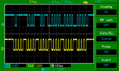
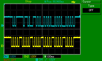
After probing both digital output pins signals with an oscilloscope here is what it looks like.
you can see that one of the pins works as a clock for synchronizing data transmission (CLK line) and the other one is the data line, so we are dealing with a synchronized data transmission protocol.
It turns out that : - Data is sent in logic level of 1.5 Volts (sounds logical as it's the same voltage as the vernier battery) - Data is sent in 6 nibbles (6 x 4 bits) with a total of 24 bits - There is about 200 mS between the end of each data packet and the beginning of the other
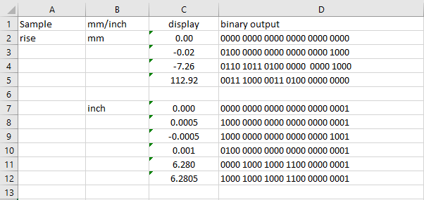
i decided to sample the data at the rising edge of the clock so after trying with different measures on the caliper and changing its mode from (mm to in) and also displaying some negative values i got this table (3rd pictures) for my test conditions and i started figuring out the communication protocol
So after studying the captured data :
- in mm mode: bits no.1 to 16 are the binary representation for the displayed number on the caliper (multiplied by 100)
- in (inch) mode : bits no.2 to 17 are the binary representation for the displayed number on the caliper (multiplied by 1000)
- bit no.21 represents the negative sign (1 if the displayed number is negative and 0 if it's positive)
- bit no.24 represents the measuring unit (1 if unit is (in) and 0 if the unit is (mm))
- in (inch) mode : bit no.1 represents the 0.5 mil segment (1 if it's added and 0 if it's not)
Making a Logic Converter
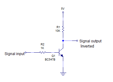
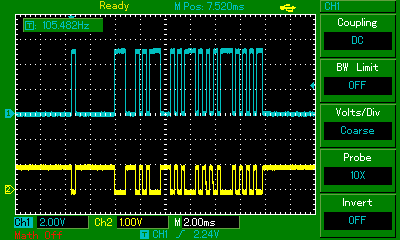
Now we need to shift the voltage level of the caliper data (1.5 volts is not suitable to work with Arduino, it's too low)
I've added a schematic for the logic converter i made for this project but as you can see the data now in addition to being shifted to 5 volts logic level it will be also inverted so we need to compensate that in the code.
Arduino Code
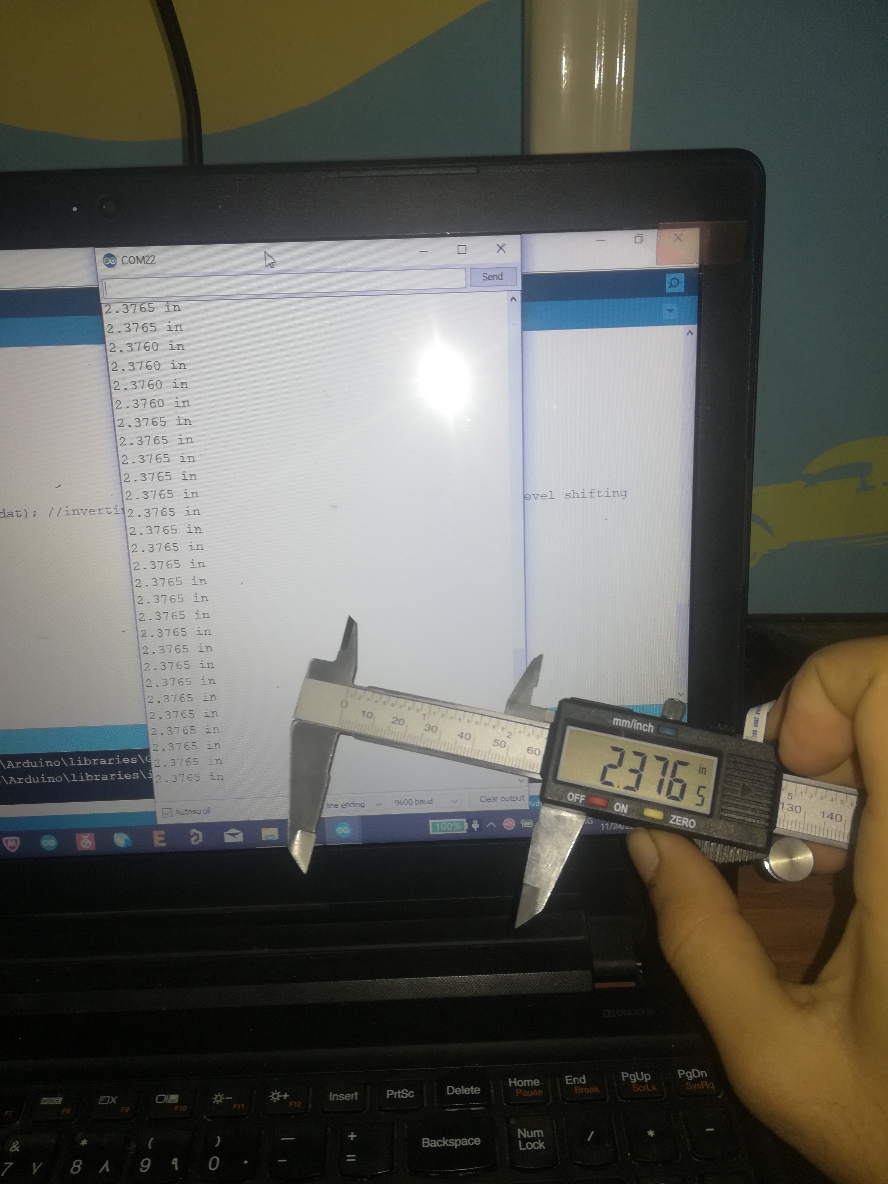
And now you are ready to connect it with the Arduino.
You can find the code attached.
connect the clock pin to pin 2 or 3 on Arduino uno, nano or pro-mini (you will need an interrupt capable pin)
connect data pin to any other pin.
Upload the code and open the serial monitor to see the measured data
The code can automatically detect what mode the caliper is working on by scanning the 24th data bit