Hack a UT373 Mini Tachometer and Connect It to an Arduino
by Ahmed_Ragab in Circuits > Lasers
2501 Views, 7 Favorites, 0 Comments
Hack a UT373 Mini Tachometer and Connect It to an Arduino


Hello Everyone :D,
In today's Instructable we're going to hack a UT373 Mini Tachometer from UNI-T and connect it to an Arduino.
After connecting it to the Arduino we're going to upload a simple sketch so that the Arduino will be able to calculate the motor's RPM (Revolutions Per Minute) just as the original tachometer is doing.
This extracted data can be used in many ways such as feedback sensor of a motor's speed or just logging it and saving it for further use or analysis.
What is a tachometer ?! Well simply it is a device that is able to measure a motor's shaft rotation speed, it has many different types, mainly mechanical and electrical tachometers.
Supplies
Supplies needed for this project are:
1 - Soldering iron and solder wire
2 - Arduino board (Uno - Nano - Pro Mini)
3 - Jumper wires
4 - A UT373 Mini tachometer, of course :D
5 - If you want to show the results on an external display then you will need a 16x2 Character LCD + PCF8574 LCD I2C Interface module (optional)
6 - Oscilloscope (Optional)
How Does This Tachometer Work?


1 - This device (Optical tachometer) uses a LASER diode that shines light over the motor shaft or fan blades in front of the tachometer
2 - When light hits a fan blade or a shiny section of the motor shaft it will get reflected back to the tachometer (You should use a shiny or white sticker that covers a portion of the motor shaft so light can be reflected back from it)
3 - The reflected light beam gets detected by a photo diode on the tachometer board
4 - A signal conditioning circuit then handles the return signal and convert it to a square wave with frequency that equals the motor shaft Revolution Per Second (RPS) then multiplies it by 60 and displays the motor Revolutions Per Minutes (RPM)
You can read more about how they work here.
Open the Tachometer

To open this tachometer:
1 - Open the battery compartment and carefully remove the batteries
2 - Remove the two screws in the battery compartment
3 - Remove the two screws near the upper edge of the tachometer
4 - Open the case by sliding it in the upper direction
PCB Quick Analysis


As you can in the first picture the PCB is divided into 5 sections
1 - Device power supply and regulator section:
Which is base on:
a - a 3.3V SMD voltage regulator with markings (4B2F) on it, probably TAR5SB33 3.3V voltage regulator
b - 1 NPN transistor (MMBT3904) with markings (1AM)
c - 1 PNP transistor (MMBT3906) with markings (2A), used as a high side switch for the LASER diode
2 - Microcontroller section:
This section is based on:
a - STM8L052C6 8-Bit Ultralow power microcontroller (datasheet), with up-to 4x28 segments LCD driver
I was surprised that they used the LQFP package of the Microcontroller and not a Chip On Board package as usual.
The microcontroller receives a square wave signal from the signal conditioning section, Turns on and off the LASER diode and the backlight LED and drives the device LCD.
b - programming header pins
c - 3.999 MHz crystal oscillator
3 - LASER Diode and backlight switches:
This section is based on:
a - 1 MMBT3904 NPN Transistor for low side switching of the LASER diode
b - 1 MMBT3904 NPN Transistor for low side switching of the backlight LED
4 - LASER Diode and photodiode PCB:
This is a small PCB that only has the LASER diode and the receiver photodiode soldered on it, and the tiny PCB itself is soldered perpendicularly over the main PCB
5 - Signal conditioning circuit:
This partition is based on the LM358 dual operational amplifier IC which converts the analog signal returning from the photodiode into a square wave with frequency equals to the received rotation speed in (Revolutions Per Second)
As you can see in the third picture, the top layer of the PCB only contains the LCD, the keypads and their rubber pads.
Be careful not to disconnect the LCD from its rubber zebra strip because it will be difficult to return them back as they were.
Powering Up the Device


In order to read signals from the device, it should be powered up !
But the device only gets powered up when the case is closed because only when the case is closed, the battery compartment pins get in contact with the battery large pads on the PCB.
We cannot solder any wires to these pads, because when we close the device back, the pads will have solder remaining on them so their contact with the battery compartment pins will not be as good and smooth as before, even if used solder wick to remove as much solder as possible.
with a quick look around I found two pin pads with - and + 4.5V text around them, a continuity test with the multimeter showed that they are connected directly to the battery pads, most probably they were used in device factory testing.
The ( - ) signed pad is directly connected to the device ground and the ( +4.5V ) signed pad is directly connected to the device + large battery pad.
So I soldered two wires to those pads and set my power supply to 4.5V with current limit set to 50 mA to avoid any damage incase of short circuits or leads touching each other.
The white jumper is ground and the Orange jumper is +4.5V
I tested this setup and everything worked as intended.
Start Reverse Engineering, LCD Signals Probing?
What is the purpose of this hack ? We want to transfer what the tachometer is reading to the Arduino board, The Arduino should read 100 RPM when the meter is displaying 100 RPM and so on...
The most direct way to do that is to capture the signals sent to the LCD display segments, decode them to know which segment is turned on and which is turned off and so we can know what the tachometer display is showing.
Easy right ?,Actually No, not as easy as it might sound.
Driving Liquid Crystal Display (LCD) segments is not done by just sending 1's and 0's as it takes to drive an LED display.
LCD segments are driven by square waves, and the phase difference between these square waves determines if the segment will be turned on or turned off.
It gets also more complicated when segments need to be multiplexed, the previously mentioned square waves become a multi-voltage levels pulses.
You can see the driving pulse of just one segment of this device in the picture attached to this step.
So for reverse engineering these waveforms and decoding them we need to have a powerful, fast enough microcontroller with plenty of ADC inputs, and enough space for the extra wiring of course.
Let's keep this approach as plan Z for now :D, and see how can we extract data from this device in an easier way.
You can start with this EEVBLOG video to start learning about LCD driving
Exposed Pads Everywhere !!
One of the approaches I like to use when reverse engineering a PCB is to look around for unused or exposed pads on the PCB, these pads are probably used by the device factory to measure some parameters, program the microcontroller on-board, and test the PCB using their test kits.
You can see that we used two exposed pads to power up the device in step 4, so you can see how they might help you during the process of reverse engineering.
When I looked around, I found three exposed pads between the microcontroller and the programming headers, one pad near the LASER diode and photodiode PCB and one pad near the LM358 op-amp.
The Three Pads Near the Microcontroller


When I had a closer look on these three pads I found that they are connected to the MCU pins (PC4, PC5, PC6)
These pins has the following functions:
PC4: USART1 synchronous clock / I2C1_SMB / Configurable clock output / LCD segment 24/ ADC1_IN4
PC5: LSE oscillator input / [SPI1 master/slave select] / [USART1 transmit]
PC6: LSE oscillator output / [SPI1 clock] / [USART1 receive]
As you can see, they all can be used as a serial USART channel 1, so I probed them using an oscilloscope to see if they are sending any data to capture.
But, I couldn't see any data on any of the three pads (See attached picture number 2 in this step), The three pads had the same form, they are just held LOW
They may be waiting for some command to start communication as this reverse engineered UT390B Laser distance meter device
But for now, I don't know or have any way to activate data sending on these pads, If they are sending data in the first place.
If we can get UART data out of these pins, then it will be just a matter of receiving the data stream and decoding it to extract data from it.
For now, let's find out what the other two exposed pads are having for us.
The Pad Next to the Photodiode


Another pad I probed on was this exposed pad beside the photodiode and LASER diode small PCB.
I put the tachometer in front of a PC fan and connected the oscilloscope probe to this pad and look what I found !!
There was a pulsating waveform with a frequency of 54.56 Hz which equals (54.56 RPS or 3273 RPM), and the tachometer was already giving readings around 3270 RPM, so we can use this pad for further analysis and complete this hack.
Actually it was expected because when continuity checked with a multimeter, this pas was directly connected to the Anode of the photodiode, so it will give direct relation to the measured shaft RPM value.
This waveform can be interfaced with the Arduino using an ADC input pin because it is shifted and has no digital nature at all.
This pad also is coming directly from the photodiode so it will need buffering before connection with Arduino, so let's keep this pad as plan B and see what the last pad is having for us.
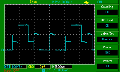
The Pad Next to the LM358 Op-amp


When I put the tachometer in front of the working PC fan and probe this pad using the oscilloscope I found a square wave with also the same frequency (54.56 Hz = 54.56 Revolution Per Second = 3273 RPM), the square wave was having a peak value of 3.0V which is suitable for both Arduino and 3.3V logic level devices as STM devices of ESPs
This pad is connected to the microcontroller of the device and also connected to the output of one of the two op-amps of the LM358 IC, this op-amp is wired in a voltage follower (buffer) configuration so the signal is already buffered.
I decided to use this pad to be connected to the Arduino and complete the hack with it, you can add a buffer or current limiting resistor between the signal pad and the Arduino pin if you want.
The next steps were that I:
a - soldered a jumper wire to the chosen pad
b - de soldered the 4.5V jumper, it is not needed anymore and the device will be getting its power from the battery compartment
c - kept the ground jumper to establish a common ground connection between the tachometer and the Arduino
d - assembled back the tachometer case and started writing some code
Calculations


The next steps after closing back the tachometer case are:
1 - Connect the signal jumper to a hardware interrupt capable pin
(Pin 2 or 3 for Arduino Uno, Nano or Pro Mini), I used pin 2 in the uploaded sketches
2 - When a pulse is indicated by the interrupt hardware inside the Micronctroller (set for interrupting at falling edge), the interrupt ISR function is called which is UT373_Micros();
3 - In the UT373_Micros() function, the micros() value at the time of triggering is saved to a variable called signalMicros, we should subtract the previous pulse micros() value which is saved to the variable lastMicros from the current signalMicros, the result from this subtraction is the periodic time of the waveform.
note: micros() functions is a function that is built-in in the Arduino platform and returns the time passed since the start of the current program and returns it in the unit of microseconds
4 - To calculate the frequency of the waveform which is also the Revolutions Per Second (RPS value) we should apply the relation ( frequency = 1 / periodic time ).
And because the periodic time is in microseconds, the relation becomes ( frequency = 1,000,000 / periodic time )
To calculate the Revolutions Per Minute (RPM value) the relation is ( RPM = frequency * 60 )
To calculate the Rad/Sec the relation is ( Rad_Per_Sec = RPSValue * 2 * PI; )
Code Uploading


After connecting the signal pin to Arduino pin 2, you can use any of the three uploaded sketches to try this project.
The first sketch (UT373_Hack_SerialMonitor) displays the calculated RPM & RPS values only on the serial monitor and you don't need to install any extra libraries for that.
The second sketch (UT373_Hack_1602LCD) displays the calculated values on serial monitor and also on a 16x2 character LCD, you can connect the LCD as seen in the first picture attached to this step and you can read more about how to use character LCDs with Arduino in this Instructable.
The third sketch (UT373_Hack_1602LCD_I2C) displays the calculated values serial monitor and on a 16x2 character LCD that uses the PCF8574 I2C module, you will need to download the LiquidCrystal_I2C library from here and check to see what is the correct I2C address of your module using the I2C scanner library.
If your module has a PCF8574 Chip from Texas Instruments then the address is probably 0x27
If your module has a PCF8574 Chip from NXP then the address is probably 0x3F
Final Thoughts
After completing this hack, I feel like using it around in more projects, maybe for datalogging projects, it can be very helpful also as a feedback sensor for motor's speed PID tuning experiments or so.
The refresh rate of the Arduino display is much faster than the refresh rate of the tachometer, this can be considered as an advantage.
The Arduino displayed values are very accurate, they can around + or - 5 counts off.
Also, you can always make your own DIY tachometer, GreatScott has a very good Instructable on that of course, but this hack is intended for someone who wants to use this tachometer as a daily kind of robust device while also being able to interface it with an external microcontroller if needed to.
In the end, Happy hacking, this was an interesting project for me to work on and hope you like it :D :D